Latest garden project (pics) but wiring question
Discussion


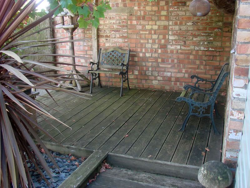
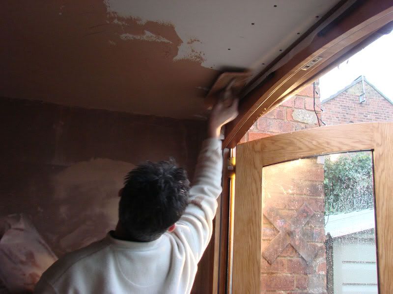
Been putting together a little project (for the wife really) over the last couple of months.
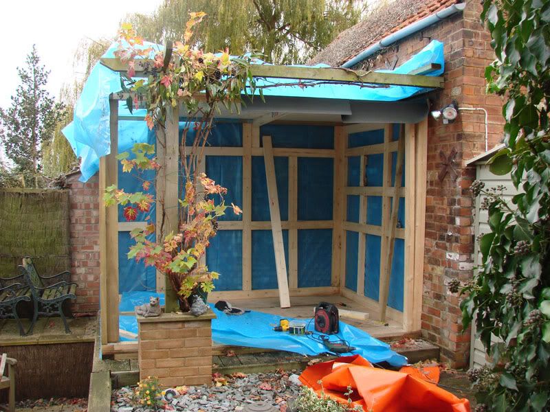
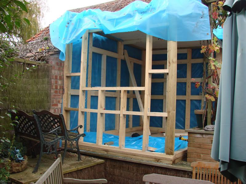
Had a dead bit of decking we never used so we decided to put a home office up there. That is next door's old barn wall there on two sides.
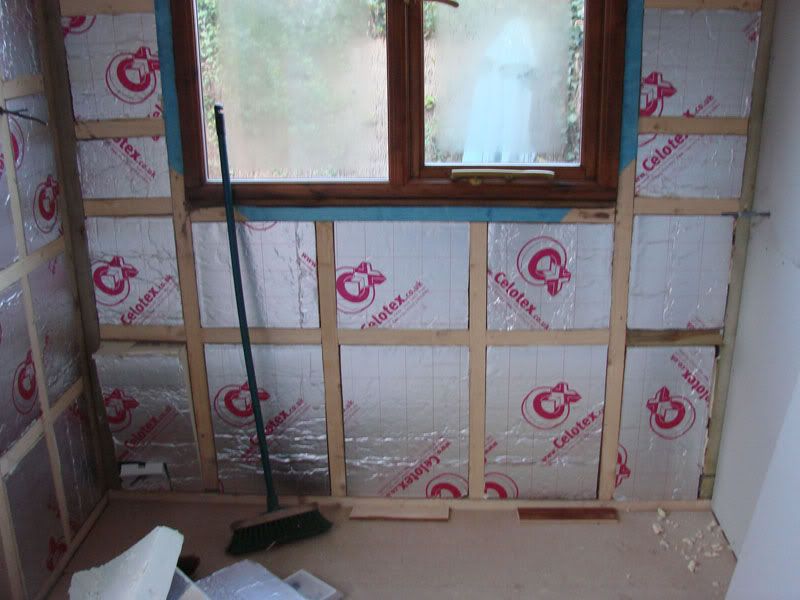
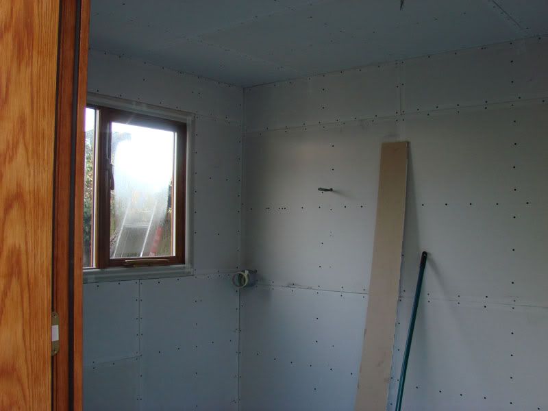
I ahve done it properly, fully insulated, sheetd, cladded etc, and wired up the power and lights on the inside.
But ... I now have four wires (one ring for the lights and one ring for the power) coming from the underneath of this thing into my shed (on the right, the light green thing) where I have power (which comes from the garage - RCD fitted etc)
What kind of box do I want in the shed to be ablt to wire this up two - I feel like I want a box with maybe a big power switch and two inputs or something - don't worry - I am not going to be wire this up - my sparky mate is going to do that - but i can't get hold of him at present - I thnk he may well be away working - and so I need to get cracking and get this bit bought and installed in the shed (so he can wire it up when he gets back)
Any ideas? I have armoured cable coming INTO the shed form the garage (buried) and this goes into a set sockets and swithces for thwe shed and some outside lights ...
I thought I may want something like this ...
http://www.screwfix.com/prods/53010/Electrical-Sup...
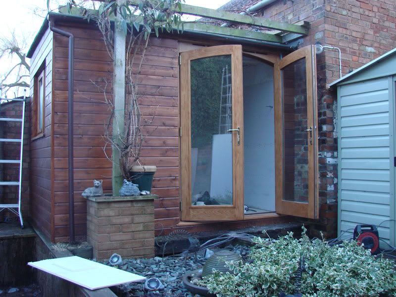
Had a dead bit of decking we never used so we decided to put a home office up there. That is next door's old barn wall there on two sides.
I ahve done it properly, fully insulated, sheetd, cladded etc, and wired up the power and lights on the inside.
But ... I now have four wires (one ring for the lights and one ring for the power) coming from the underneath of this thing into my shed (on the right, the light green thing) where I have power (which comes from the garage - RCD fitted etc)
What kind of box do I want in the shed to be ablt to wire this up two - I feel like I want a box with maybe a big power switch and two inputs or something - don't worry - I am not going to be wire this up - my sparky mate is going to do that - but i can't get hold of him at present - I thnk he may well be away working - and so I need to get cracking and get this bit bought and installed in the shed (so he can wire it up when he gets back)
Any ideas? I have armoured cable coming INTO the shed form the garage (buried) and this goes into a set sockets and swithces for thwe shed and some outside lights ...
I thought I may want something like this ...
http://www.screwfix.com/prods/53010/Electrical-Sup...
Well the bit you have linked to fits inside a consumer unit, so you'll need one of those too.
My garage has an armoured feed coming underground from the house into one of these:
http://www.screwfix.com/prods/54580/Electrical-Sup...
with two separate MCBs
http://www.screwfix.com/prods/80561/Electrical-Sup...
one for the power and one for the lighting. Off the top of my head lighting is 6A and power is 32A but I would get someone qualified to confirm this!
Thanks James, yes that's the kinda thing (that you linked to) ...
Couldn't find a two-way one though - they must do one - don't need another RCD as have one already in the garage.
Not sure on exactly what MCB's I need though - I have four lights and three double sockts - each on a ring.
Couldn't find a two-way one though - they must do one - don't need another RCD as have one already in the garage.
Not sure on exactly what MCB's I need though - I have four lights and three double sockts - each on a ring.
OKay - got all that - all in - but a problem ...
Sockets work fine - lights work fine - but switch keeps tripping the RCDs ... HOW do I wire the switch up?
I have cable from power source to switch - (twin & earth) and the same FROM the switch to the lights in the ring - but cannot understand how to wire the switch ... I must be missing something simple ...
Run all 3 from lighting supply to the switch and drop the earth in the switch and live to COM connector in the switch.
Continue from the switch to run the unbroken common to the COM side of the lamp unit, and continue the earth to the Lamp unit.
Take the live out of the L1 side of the switch to the live side of the lamp holder, and mark the red wire with black tape to signify a switched live.
Should all work.
Continue from the switch to run the unbroken common to the COM side of the lamp unit, and continue the earth to the Lamp unit.
Take the live out of the L1 side of the switch to the live side of the lamp holder, and mark the red wire with black tape to signify a switched live.
Should all work.
SeeFive said:
Run all 3 from lighting supply to the switch and drop the earth in the switch and live to COM connector in the switch.
Continue from the switch to run the unbroken common to the COM side of the lamp unit, and continue the earth to the Lamp unit.
Take the live out of the L1 side of the switch to the live side of the lamp holder, and mark the red wire with black tape to signify a switched live.
Should all work.
Cheers Kev, but ...Continue from the switch to run the unbroken common to the COM side of the lamp unit, and continue the earth to the Lamp unit.
Take the live out of the L1 side of the switch to the live side of the lamp holder, and mark the red wire with black tape to signify a switched live.
Should all work.
Red wire?
I have three wires coming to the switch ... (from the power source via the consumer unit)
I have three wires leaving the switch ... going to a light - from there I have three wires coming out again - going to another light and so on - a total of five lights - these then return to the consumer unit.
So the live goes into the COM on the switch but leaves the switch via the L1 connector - and this is then marked as the switched live ...
So the neutral would be terminal blocked and joined (bypassing the switch?)
Without ANY switch in and SIX wires hanging out the hole where the switch goes, all the lights are on and work fine - but I can't keep switching them off via the CU!

FOUND THIS ON THE NET ...
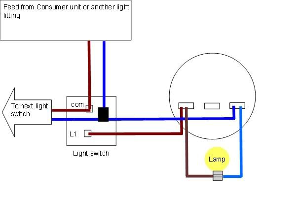
I don't have another *switch* for the wires to go to just a series of lights ...
Does this look right?
Edited by MikeyT on Sunday 24th January 19:53
Edited by MikeyT on Sunday 24th January 19:54
SeeFive said:
Run all 3 from lighting supply to the switch and drop the earth in the switch and live to COM connector in the switch.
Continue from the switch to run the unbroken common to the COM side of the lamp unit, and continue the earth to the Lamp unit.
Take the live out of the L1 side of the switch to the live side of the lamp holder, and mark the red wire with black tape to signify a switched live.
Should all work.
Cheers Kev, but ...Continue from the switch to run the unbroken common to the COM side of the lamp unit, and continue the earth to the Lamp unit.
Take the live out of the L1 side of the switch to the live side of the lamp holder, and mark the red wire with black tape to signify a switched live.
Should all work.
Red wire?
I have three wires coming to the switch ... (from the power source via the consumer unit)
I have three wires leaving the switch ... going to a light - from there I have three wires coming out again - going to another light and so on - a total of five lights - these then return to the consumer unit.
So the live goes into the COM on the switch but leaves the switch via the L1 connector - and this is then marked as the switched live ...
And the neutral wires are terminal blocked and joined (bypassing the switch) ...
Without ANY switch in and SIX wires hanging out the hole where the switch goes, all the lights are on and work fine - but I can't keep switching them off via the CU!
Found this on the net ...
Edited by MikeyT on Sunday 24th January 19:56
SeeFive said:
Run all 3 from lighting supply to the switch and drop the earth in the switch and live to COM connector in the switch.
Continue from the switch to run the unbroken common to the COM side of the lamp unit, and continue the earth to the Lamp unit.
Take the live out of the L1 side of the switch to the live side of the lamp holder, and mark the red wire with black tape to signify a switched live.
Should all work.
NO NO NO do not mark a red wire with black tape when the red is live, black denotes a neutral conductorContinue from the switch to run the unbroken common to the COM side of the lamp unit, and continue the earth to the Lamp unit.
Take the live out of the L1 side of the switch to the live side of the lamp holder, and mark the red wire with black tape to signify a switched live.
Should all work.
OP lighting doesn't need to be wired in a ring, it should be done as a radial
take 1 1.5 twin and earth from your circuit breaker/db to your first light (lightswitch can be used in a slightly different way if you are not using ceiling roses/joint boxes)
you now have live (permanent),neutral and cpc at this point. -mark the cable as feed, biro or permanent marker will do fine
from your first light take a cable down to the switch (i assume 1 switch is doing all lights? more switches or 2 way switching can be done though) - mark the cable as sf+sw (switch feed+switch wire)
are you using red/black or brown/blue cable- i assume new colours of brown/blue exept where it meets the older existing armoured cable
it should be
red=brown
black=blue
ALTHOUGH THIS CAN NOT BE GUARENTEED if you are picking up existing cables where lighting is concerned
at the switch connect brown(sf) to com
connect blue(sw) to L1- mark with brown tape to denote live
keeping the marking on the cable at the light/re mark
Strip back the cable marked feed, sleeve the cpc with green/yellow sleeving
strip back the cable marked sf+sw, sleeve as before
connect the 2 browns together
connect the blue((sw)taped brown) from the cable(sw+sf) to your first light
connect the blue from the feed to your first light (neutral)
ensure all cpc- earth cables are connected together
This would get the first light working and switching correctly
to add another light to the same switch, take a cable from the first light to the 2nd, 3rd etc- connect l,n,e as you would expect
to get them working- at the first light connect neutral and cpc to other cables
and the live brown with the sw (blue cable taped brown)
MikeyT said:
as you look at the connections in the ceiling rose(light connections) you will see the middle has not beed used, this is where you should connect the feed in together with the feed to the switch.
Edited by Brite spark on Sunday 24th January 21:10
Brite spark said:
MikeyT said:
as you look at the connections in the ceiling rose(light connections) you will see the middle has not beed used, this is where you should connect the feed in together with the feed to the switch.
Edited by Brite spark on Sunday 24th January 21:10
Does the above diagram seem okay? (Bearing in mind I only have the ONE switch)
Without meaning to be rude, you obviously don't know enough about electrics to be doing this sort of work. Legally this should have been notified to your local Council under Part P of the building regulations, or carried out by a qualified electrician who was able to self certify. I assume that neither applies in this case or you wouldn't be asking these sort of questions, and you wouldn't have a lighting circuit on a ring.
That aside (and I'm no fan of Part P it should be mentioned), you should consider getting an electician to check things over. The main reason that electrics in outbuildings come under Part P is because you have to be extremely careful about the earthing arrangements. Just connecting the earth into the neighbouring shed won't guarantee it's safe. You need to get someone to check that the circuits will trip in time if there's a fault, to prevent either a fire or someone getting killed.
That aside (and I'm no fan of Part P it should be mentioned), you should consider getting an electician to check things over. The main reason that electrics in outbuildings come under Part P is because you have to be extremely careful about the earthing arrangements. Just connecting the earth into the neighbouring shed won't guarantee it's safe. You need to get someone to check that the circuits will trip in time if there's a fault, to prevent either a fire or someone getting killed.
Trevelyan said:
Without meaning to be rude, you obviously don't know enough about electrics to be doing this sort of work. Legally this should have been notified to your local Council under Part P of the building regulations, or carried out by a qualified electrician who was able to self certify. I assume that neither applies in this case or you wouldn't be asking these sort of questions, and you wouldn't have a lighting circuit on a ring.
That aside (and I'm no fan of Part P it should be mentioned), you should consider getting an electician to check things over. The main reason that electrics in outbuildings come under Part P is because you have to be extremely careful about the earthing arrangements. Just connecting the earth into the neighbouring shed won't guarantee it's safe. You need to get someone to check that the circuits will trip in time if there's a fault, to prevent either a fire or someone getting killed.
Yeah, thanks, but I'm not actually doing it! That aside (and I'm no fan of Part P it should be mentioned), you should consider getting an electician to check things over. The main reason that electrics in outbuildings come under Part P is because you have to be extremely careful about the earthing arrangements. Just connecting the earth into the neighbouring shed won't guarantee it's safe. You need to get someone to check that the circuits will trip in time if there's a fault, to prevent either a fire or someone getting killed.
It's a bit tricky because an electrician mate of mine is ... and all has been okay until the switch ... and even he's not sure (so, some electrician) ... I was just asking the PH masses ...
But you live and learn. Rest assured it will be 100% safe in the end. SO, about that diagram ...

Edited by MikeyT on Sunday 24th January 22:18
MikeyT said:
SeeFive said:
Run all 3 from lighting supply to the switch and drop the earth in the switch and live to COM connector in the switch.
Continue from the switch to run the unbroken common to the COM side of the lamp unit, and continue the earth to the Lamp unit.
Take the live out of the L1 side of the switch to the live side of the lamp holder, and mark the red wire with black tape to signify a switched live.
Should all work.
Cheers Kev, but ...Continue from the switch to run the unbroken common to the COM side of the lamp unit, and continue the earth to the Lamp unit.
Take the live out of the L1 side of the switch to the live side of the lamp holder, and mark the red wire with black tape to signify a switched live.
Should all work.
Red wire?
I have three wires coming to the switch ... (from the power source via the consumer unit)
I have three wires leaving the switch ... going to a light - from there I have three wires coming out again - going to another light and so on - a total of five lights - these then return to the consumer unit.
So the live goes into the COM on the switch but leaves the switch via the L1 connector - and this is then marked as the switched live ...
So the neutral would be terminal blocked and joined (bypassing the switch?)
Without ANY switch in and SIX wires hanging out the hole where the switch goes, all the lights are on and work fine - but I can't keep switching them off via the CU!
FOUND THIS ON THE NET ...
I don't have another *switch* for the wires to go to just a series of lights ...
Does this look right?
Edited by MikeyT on Sunday 24th January 19:53
Edited by MikeyT on Sunday 24th January 19:54
Diagram looks right to me. The wire coming from L1 is your switched live. The other wire is the common. There will also be an earth that will require connecting to each lamp unit, but you know that. You do not need another switch - that is fine ignore that aspect of the diagram. Make sure that you mark the switched live in some way - as code suggested by sparks, but definitely mark it.
Ok, the first light will work from the switch, so now it is a case of replicating that set of connections to the next light unit. Take the switched live, earth and neutral to the next lamp and connect in the same way... ad nauseum for each lamp.
The question I have, is why are you returning to the consumer unit, and how are you connecting the cables (I assume that you are trying to do some sort of ring which as others have suggested is not necessary here)? This is probably why your switch does not work. If you are wired as per the diagram, it is receiving a switched live from the switch, but also receiving a constant live from the return to the CU is my best guess, hence you have to switch the CU to drop the live feed.
Id suggest disconnecting the return to CU and wire as per the diagram you have shown daisy chaining the lamp units together with no return to CU from the last lamp.
Gassing Station | Homes, Gardens and DIY | Top of Page | What's New | My Stuff