Discussion


Hi all
After a bit of advice on here many months ago, I’ve finally got around to buying a VFD to wire a 3ph pillar drill into my single phase garage.
I’ve purchased a VFD on eBay and have also bought one of these: https://www.amazon.co.uk/415V-Interlock-Socket-Swi...
In the location in the garage where I intend to install the 5 core socket there is a single standard socket on its own breaker directly from the consumer unit.
I was planning to extend this ring into the VFD with some twin and earth. Then come out of the VFD with 5 core wire and into the above socket mounted on the wall next to the VFD
Then I was going to plug the pillar drill into the socket. Leaving the flexibility of using other 3ph tools should the need arise.
My pillar drill plug has a 4 core wire as follows

So, can anyone help me with the wiring. What colour cable goes into which outputs on the VFD? And is it ok to wire it to a socket as above or do I need to wire the drill directly into the VFD?
Please don’t tell me to call a professional. I want to learn. I’m not daft. And I will be throwing the power off to the whole garage before I do anything. I’ve wired many a single phase ring main before.
And of course once completed I’ll be calling out a sparky to check and sign it off. But I’d like to wire it all up properly myself first.
Practical advice required please.
After a bit of advice on here many months ago, I’ve finally got around to buying a VFD to wire a 3ph pillar drill into my single phase garage.
I’ve purchased a VFD on eBay and have also bought one of these: https://www.amazon.co.uk/415V-Interlock-Socket-Swi...
In the location in the garage where I intend to install the 5 core socket there is a single standard socket on its own breaker directly from the consumer unit.
I was planning to extend this ring into the VFD with some twin and earth. Then come out of the VFD with 5 core wire and into the above socket mounted on the wall next to the VFD
Then I was going to plug the pillar drill into the socket. Leaving the flexibility of using other 3ph tools should the need arise.
My pillar drill plug has a 4 core wire as follows
So, can anyone help me with the wiring. What colour cable goes into which outputs on the VFD? And is it ok to wire it to a socket as above or do I need to wire the drill directly into the VFD?
Please don’t tell me to call a professional. I want to learn. I’m not daft. And I will be throwing the power off to the whole garage before I do anything. I’ve wired many a single phase ring main before.
And of course once completed I’ll be calling out a sparky to check and sign it off. But I’d like to wire it all up properly myself first.
Practical advice required please.
The plug should have L1, L2 and L3 marked on next to 3 of the pins, those are your three phases; the VFD will have L1, L2 and L3 marked on the output terminal block. TBH I'd consider getting rid of the drill's existing start/stop switch and controlling via the VFD, VFDs can be fussy about being directly wired to their load and may behave oddly if there's a switch between them.
Edited by hidetheelephants on Friday 5th September 21:02
whats the vfd.... ? you have a link....
Some take 240v in and make three phase but the voltage out isnt 415v but lower so the drill motor needs to be connected in delta...
You say about wiring the ring to the vfd... thats a no... have an isolator switch then connect switch to vfd.
direct connection isnt wise. would like a way to quickly dosconnect the vfd incase it catches fire, its electronic and always a risk.
https://www.practicalmachinist.com/forum/threads/2...
Having 1 VFD for multiple devices seems superficially attractive, it was certainly popular in the past when such things were very expensive and most made do with rotary or static converters(also expensive) powering several machines, but given how cheap they have become in the last decade I'd give it a miss.
ruggedscotty said:
whats the vfd.... ? you have a link....
Some take 240v in and make three phase but the voltage out isnt 415v but lower so the drill motor needs to be connected in delta...
You say about wiring the ring to the vfd... thats a no... have an isolator switch then connect switch to vfd.
direct connection isnt wise. would like a way to quickly dosconnect the vfd incase it catches fire, its electronic and always a risk.
https://www.practicalmachinist.com/forum/threads/2...
This one. https://ebay.us/m/TxZjN4Some take 240v in and make three phase but the voltage out isnt 415v but lower so the drill motor needs to be connected in delta...
You say about wiring the ring to the vfd... thats a no... have an isolator switch then connect switch to vfd.
direct connection isnt wise. would like a way to quickly dosconnect the vfd incase it catches fire, its electronic and always a risk.
https://www.practicalmachinist.com/forum/threads/2...
I’ve bought an isolator switch box to go next to the plug socket before the VFD. Good call.
Edited by eltax91 on Saturday 6th September 09:32
Mr Pointy said:
We need a better picture of the connector & wiring as it looks like one of the cores is hidden. The VFD seems have a delta output (3 phases plus earth) but your drill man be star connected (3 phases plus neutral & earth).
The wire fitted to the drill have 4 cores. Brown, blue, yellow/green and black. No grey wire. It was previously resident in a small machine shop with 3ph power, belonging to my mates late father.
eltax91 said:
This one. https://ebay.us/m/TxZjN4
That VFD looks like it's supposed to rail mount inside another enclosure? The terminals are touch resistant up to a point but they aren't exactly covered from what I can see. JoshSm said:
eltax91 said:
This one. https://ebay.us/m/TxZjN4
That VFD looks like it's supposed to rail mount inside another enclosure? The terminals are touch resistant up to a point but they aren't exactly covered from what I can see. eltax91 said:
JoshSm said:
eltax91 said:
This one. https://ebay.us/m/TxZjN4
That VFD looks like it's supposed to rail mount inside another enclosure? The terminals are touch resistant up to a point but they aren't exactly covered from what I can see.  Thought it worth asking as sometimes people don't know better & create a hazard.
 eltax91 said:
The wire fitted to the drill have 4 cores. Brown, blue, yellow/green and black. No grey wire.
It was previously resident in a small machine shop with 3ph power, belonging to my mates late father.
The blue wire should be grey if its a 3 phase supply, blue is used for neutral.It was previously resident in a small machine shop with 3ph power, belonging to my mates late father.
The VFD terminals R,S & T are for a 3 phase input power supply and the U,V & W terminals are a 3 phase output controlling the motor speed.
Are you sure its a 3 phase motor and if so what is the Kw rating? Wouldn't want you going up in a puff of smoke
Gladers01 said:
eltax91 said:
The wire fitted to the drill have 4 cores. Brown, blue, yellow/green and black. No grey wire.
It was previously resident in a small machine shop with 3ph power, belonging to my mates late father.
The blue wire should be grey if its a 3 phase supply, blue is used for neutral.It was previously resident in a small machine shop with 3ph power, belonging to my mates late father.
The VFD terminals R,S & T are for a 3 phase input power supply and the U,V & W terminals are a 3 phase output controlling the motor speed.
Are you sure its a 3 phase motor and if so what is the Kw rating? Wouldn't want you going up in a puff of smoke
Yabu said:
Blue cable looks like it’s in the connection for L3, nothing in the neutral terminal, the previous user may have had wiring in the socket to match or someone may have used 4 core cable with the blue as L3 and not as neutral as a balanced 3 phase motor doesn’t need it/msy not have a neutral connection
Certainly looks that way with the motor wired in delta rather than a star configuration without the need for a neutral connection 
Gladers01 said:
The blue wire should be grey if its a 3 phase supply, blue is used for neutral.
The VFD terminals R,S & T are for a 3 phase input power supply and the U,V & W terminals are a 3 phase output controlling the motor speed.
Are you sure its a 3 phase motor and if so what is the Kw rating? Wouldn't want you going up in a puff of smoke
The VFD terminals R,S & T are for a 3 phase input power supply and the U,V & W terminals are a 3 phase output controlling the motor speed.
Are you sure its a 3 phase motor and if so what is the Kw rating? Wouldn't want you going up in a puff of smoke
eltax91 said:
ruggedscotty said:
whats the vfd.... ? you have a link....
Some take 240v in and make three phase but the voltage out isnt 415v but lower so the drill motor needs to be connected in delta...
You say about wiring the ring to the vfd... thats a no... have an isolator switch then connect switch to vfd.
direct connection isnt wise. would like a way to quickly dosconnect the vfd incase it catches fire, its electronic and always a risk.
https://www.practicalmachinist.com/forum/threads/2...
This one. https://ebay.us/m/TxZjN4Some take 240v in and make three phase but the voltage out isnt 415v but lower so the drill motor needs to be connected in delta...
You say about wiring the ring to the vfd... thats a no... have an isolator switch then connect switch to vfd.
direct connection isnt wise. would like a way to quickly dosconnect the vfd incase it catches fire, its electronic and always a risk.
https://www.practicalmachinist.com/forum/threads/2...
I’ve bought an isolator switch box to go next to the plug socket before the VFD. Good call.
Edited by eltax91 on Saturday 6th September 09:32
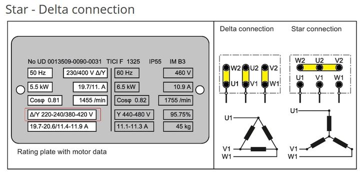
This means how the motor winding is connected. generally its a star motor running on 400 v 3ph.
Then if your using an invertor running on 220v you need to rework that motor connecton...
When you are looking at the terminals you will see links at one side linking the three together. then your 400 v goes in on the other three terminals. each of the three windings connect to the 6 terminals.
The links are moved to across the terminals and that with the wiring of the coils configurs them to delta so it can ruin on reduced voltage and make the same power.
Cable colours -
1ph Brown Blue Green/Yellow are Live Neutral Earth respectively
3ph Brown Grey Black Blue Green/Yellow are L1 L2 L3 Neutral Earth respectively
Edited by ruggedscotty on Saturday 6th September 22:13
ruggedscotty said:
Looking at this the motor has to be configured in Delta to run with the drive -
This means how the motor winding is connected. generally its a star motor running on 400 v 3ph.
Then if your using an invertor running on 220v you need to rework that motor connecton...
When you are looking at the terminals you will see links at one side linking the three together. then your 400 v goes in on the other three terminals. each of the three windings connect to the 6 terminals.
The links are moved to across the terminals and that with the wiring of the coils configurs them to delta so it can ruin on reduced voltage and make the same power.
Cable colours -
1ph Brown Blue Green/Yellow are Live Neutral Earth respectively
3ph Brown Grey Black Blue Green/Yellow are L1 L2 L3 Neutral Earth respectively
Stumps for a Delta and Wickets for a Star configuration.This means how the motor winding is connected. generally its a star motor running on 400 v 3ph.
Then if your using an invertor running on 220v you need to rework that motor connecton...
When you are looking at the terminals you will see links at one side linking the three together. then your 400 v goes in on the other three terminals. each of the three windings connect to the 6 terminals.
The links are moved to across the terminals and that with the wiring of the coils configurs them to delta so it can ruin on reduced voltage and make the same power.
Cable colours -
1ph Brown Blue Green/Yellow are Live Neutral Earth respectively
3ph Brown Grey Black Blue Green/Yellow are L1 L2 L3 Neutral Earth respectively
Edited by ruggedscotty on Saturday 6th September 22:13
The drive linked is for a 3 phase input, however they sell a single phase 220v input with a 380v three phase output with the terminals marked L,N & E at the top of the inverter and U,V & W at the bottom for the motor.
Gassing Station | Homes, Gardens and DIY | Top of Page | What's New | My Stuff