Mystery USB device on Ebay
Discussion


I bought this device purely out of interest - it's labelled as a "USB to USB digital interface".
I opened it up and there are two chips on board, STM32F401 micros.
I plugged it into a disposable Linux USB and it doesn't show up as anything - however I found a button on the back side of the board, and that puts the device in a programming mode (DFU mode), at which point it's visible in the USB stack.
Now the question is; why two STM chips and what can I do with it?
Link to the device in question
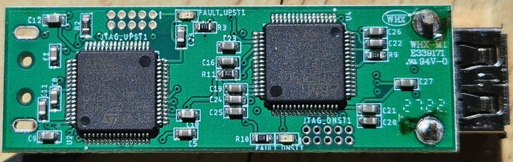
Obligatory picture! (there is a USB socket for output and a trailing cable for input).
I opened it up and there are two chips on board, STM32F401 micros.
I plugged it into a disposable Linux USB and it doesn't show up as anything - however I found a button on the back side of the board, and that puts the device in a programming mode (DFU mode), at which point it's visible in the USB stack.
Now the question is; why two STM chips and what can I do with it?
Link to the device in question
Obligatory picture! (there is a USB socket for output and a trailing cable for input).
TonyRPH said:
I bought this device purely out of interest - it's labelled as a "USB to USB digital interface".
I opened it up and there are two chips on board, STM32F401 micros.
I plugged it into a disposable Linux USB and it doesn't show up as anything - however I found a button on the back side of the board, and that puts the device in a programming mode (DFU mode), at which point it's visible in the USB stack.
Now the question is; why two STM chips and what can I do with it?
I'd presume that the ST chips are connected to each other and there are two of them because each one has one USB device interface and that's the easiest way to connect to two USB masters at the same time.I opened it up and there are two chips on board, STM32F401 micros.
I plugged it into a disposable Linux USB and it doesn't show up as anything - however I found a button on the back side of the board, and that puts the device in a programming mode (DFU mode), at which point it's visible in the USB stack.
Now the question is; why two STM chips and what can I do with it?
I would assume that the behaviour / purpose will be custom as they are generic programmable microcontrollers and you could easily implement almost anything you like over USB (most likely bulk endpoints with custom commands / behaviours).
If it was something less custom / more standard in terms of operation, then you could imagine using this hardware to connect two computers together, both ST chips enumerating as a mass storage device and enabling you to drag and drop files between them (perhaps).
Or maybe enumerating as a pair of USB audio devices (mic on one, speaker on the other) or something like that?
You should be able to query the USB vid and pid on both sides, and see what endpoints it presents?
I had a bit of a play with the device yesterday.
I'm completely out of my depth here - as I said in my OP, I had no idea what I was buying and it was really just a gamble on what I was going to get!
I've been able to program the second chip with a simple blink routine, although this wasn't 100% successful! (this LED was blinking that fast it was dim)
As I had backed up whatever was on there originally, I was able to restore the original code (which is possibly blank!).
Whilst I've done a fair bit of Arduino stuff (which I understand is similar) I just can't think of a use for this device.
It'll go on to my unknown project shelf lol.
TonyRPH said:
I bought this device purely out of interest - it's labelled as a "USB to USB digital interface".
I opened it up and there are two chips on board, STM32F401 micros.
I plugged it into a disposable Linux USB and it doesn't show up as anything - however I found a button on the back side of the board, and that puts the device in a programming mode (DFU mode), at which point it's visible in the USB stack.
Now the question is; why two STM chips and what can I do with it?
Link to the device in question
Obligatory picture! (there is a USB socket for output and a trailing cable for input).
Yeah, that's definitely a bit of an odd device. And I've done USB programming, both with an STM32F4 and with an xHCI host controller...I opened it up and there are two chips on board, STM32F401 micros.
I plugged it into a disposable Linux USB and it doesn't show up as anything - however I found a button on the back side of the board, and that puts the device in a programming mode (DFU mode), at which point it's visible in the USB stack.
Now the question is; why two STM chips and what can I do with it?
Link to the device in question
Obligatory picture! (there is a USB socket for output and a trailing cable for input).
If I had to hazard a guess, maybe some kind of USB condom. If you plugged in a USB killer it might only fry the device, rather than your USB host controller. Always use protection before inserting unknown devices into your ports.

vaud said:
is there a part number on it anywhere?
Only what's in the picture.The brand seems to be 'WHX' part number: WHX-M1E339171
There's another number whiuch I think is generic (I think I've seen it on PCBs before): 94V-0
EmailAddress said:
Similar to this?
I had wondered if it was something similar - my hope was that it was some kind of USB isolator actually (which I'd find useful as I do a lot of stuff with audio and DACs etc.).Solocle said:
Yeah, that's definitely a bit of an odd device. And I've done USB programming, both with an STM32F4 and with an xHCI host controller...
If I had to hazard a guess, maybe some kind of USB condom. If you plugged in a USB killer it might only fry the device, rather than your USB host controller. Always use protection before inserting unknown devices into your ports.
I was certainly apprehensive about connecting it, hence the use of a 'disposable' Linux box!If I had to hazard a guess, maybe some kind of USB condom. If you plugged in a USB killer it might only fry the device, rather than your USB host controller. Always use protection before inserting unknown devices into your ports.
jeremyc said:
Given the upstream and downstream JTAG interfaces, I wonder if it's a USB to JTAG adaptor to allow testing of ICs from a PC?
From what I can gather so far, one chip is purely to handle the USB host programming which programs the other chip.There are two LEDs on board, one connected to each chip as far as I can tell. One chip has a JTAG port labelled JTAG_UPST1, the other chip has a JTAG port labelled JTAG_DNST1.
Each corresponding LED is labelled FAULT_UPST1 and FAULT_DNST1 respectively.
These LEDs flash (very) randomly.
UPST1 (Upstream) I guess is connected to the USB input
DNST1 (Downstream) I guess is connected to the USB output
The board is invisible to the host until I put it in 'DFU' mode (this is achieved by holding a tiny button whilst plugging it in to the host).
EDIT: The chips are actually: STM32F401RCT6 if that makes any difference.
Edited by TonyRPH on Friday 16th May 09:24
TonyRPH said:
Only what's in the picture.
The brand seems to be 'WHX' part number: WHX-M1E339171
There's another number whiuch I think is generic (I think I've seen it on PCBs before): 94V-0
First thing I looked for when I saw the thread!The brand seems to be 'WHX' part number: WHX-M1E339171
There's another number whiuch I think is generic (I think I've seen it on PCBs before): 94V-0
WHX seems to be a contract PCB manufacturer, so perhaps nothing to discover there.
94V-0 is likely a reference to flame retardant certification of the PCB material - UL94 being the test standard, and V-0 being its performance
When you think Pistonheads has a forum for everything...
...try Reddit
https://www.reddit.com/r/PrintedCircuitBoard/
https://www.reddit.com/r/AskElectronics/
https://www.reddit.com/r/electronics/

...try Reddit
https://www.reddit.com/r/PrintedCircuitBoard/
https://www.reddit.com/r/AskElectronics/
https://www.reddit.com/r/electronics/
Gassing Station | Computers, Gadgets & Stuff | Top of Page | What's New | My Stuff