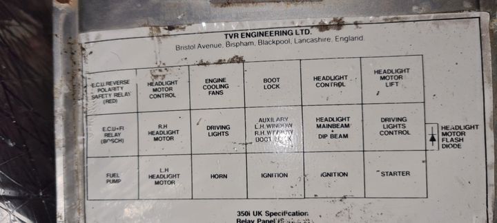
350i relay references
Discussion
I completely rebuilt the relay box of my wedge and I would like to change all the relays.
I am looking for the references of the different relays and their places in the box. I am lost between the 4 or 5 pins, 87, 87 A, 87B .....especially for the main relay and the pump relay
pic of the diagram on the ECU

Thank you for your help
I am looking for the references of the different relays and their places in the box. I am lost between the 4 or 5 pins, 87, 87 A, 87B .....especially for the main relay and the pump relay
pic of the diagram on the ECU
Thank you for your help
Edited by reb266 on Monday 4th November 21:07
Edited by reb266 on Monday 4th November 21:42
As the original relay bases were designed to latch together to create whatever size of panel was needed, it was possible - and sometimes happened - that the factory layout didn't exactly match the layout on the diagram... and that's before decades of twiddlers pulled them apart and put them back incorrectly.
The relays themselves are nothing special, Vehicle Wiring Products and others sell what you need.
For the Ignition pair you really need 30A or more. The red Pektron 'relay' isn't really a relay but a cluster of electronic components on a circuit board (properly called a steering module) so don't plug a relay in there or things will go haywire.
Essentially the 4-pin type are for circuits that are either on or off (fan, horn etc.), where the 5-pin switches current between one circuit or another (such as the headlamp pods).
This may be a red herring, but when I discovered some melting relays on my relay board there seemed to be some differences between the relays used in that some had the 87 contact in the middle of the relay and some had the 87A.
The fuel pump and I think the fan appeared to have different relays (possibly) in that the positive terminal was labelled 30/51 as opposed to 30 which was on all the others. Doing some googling (albeit a bit vague) it seemed to suggest the 51 means the relay provides some overcurrent protection which would make sense as the fuel pump and fan are going to be high power loads.
I fitted the highest rated relay I could find which was about 30/40amps from memory and one with a diode across the coil.
Good Luck
Edited by Pumpkin123 on Monday 11th November 12:02
reb266 said:
Thanks for your reply but it is specified for the Rover wiring that the pump relay is a specific relay as well as the main relay. for the other relays, the 5 pins 87/87A do the job
It was a 'specific' relay at the time because not many car electrical items had the current requirement of an injection fuel pump.There are plenty of manufacturers who offer high-current relays now. As long as the terminals are in the correct position there shouldn't be a problem.
Pumpkin123 said:
I fitted the highest rated relay I could find which was about 30/40amps from memory and one with a diode across the coil.
A diode across a relay coil is generally there to prevent back-EMF energy from damaging any electronics controlling the relay - this isn't required on the Lucas/ Bosch 'flapper' system as the ECU doesn't switch any of the relays - might make more sense if the hotwire ECU does, but even then the ECU designer should have allowed for it and included protection diodes alongside the power devices.Gassing Station | Wedges | Top of Page | What's New | My Stuff


