Solderists......
Discussion


Actually, maybe more of an electronics question.....
On my desk I have three 2x Display Port to 1x Display Port switch boxes. they let me individually switch my screens between my PC and my work laptop.
The boxes were cheap and small because they simply switch one thing and they're great. Except that they have two DP cables coming out of one side, one coming out the opposite side and a button on top.
There's no way to place one on the desk neatly, let alone 3 as the wires have to intrude. My desk is spotless apart from these, so this is sub-optimal.
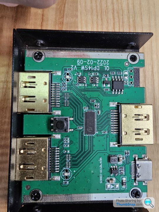
Inside there's 3 pin push-click switch which I presume is a toggle switch in operation.
If I can find another 3-pin switch that works the same way, can I simply solder the second switch to the legs of the first to build out a remote box for the switch? I can't easily desolder the switch to move it, but I reckon I can get wires onto the legs without making too much mess.
Plan is to 3D print a little control box to sit at the back of the desk, then all the switch boxes and wires can go in the back of my desk drawers hidden away.
On my desk I have three 2x Display Port to 1x Display Port switch boxes. they let me individually switch my screens between my PC and my work laptop.
The boxes were cheap and small because they simply switch one thing and they're great. Except that they have two DP cables coming out of one side, one coming out the opposite side and a button on top.
There's no way to place one on the desk neatly, let alone 3 as the wires have to intrude. My desk is spotless apart from these, so this is sub-optimal.
Inside there's 3 pin push-click switch which I presume is a toggle switch in operation.
If I can find another 3-pin switch that works the same way, can I simply solder the second switch to the legs of the first to build out a remote box for the switch? I can't easily desolder the switch to move it, but I reckon I can get wires onto the legs without making too much mess.
Plan is to 3D print a little control box to sit at the back of the desk, then all the switch boxes and wires can go in the back of my desk drawers hidden away.
paulrockliffe said:
If I can find another 3-pin switch that works the same way, can I simply solder the second switch to the legs of the first to build out a remote box for the switch? I can't easily desolder the switch to move it, but I reckon I can get wires onto the legs without making too much mess..
I think you'd need to remove the existing switch, otherwise you'll end up with issues when the local switch has connections from input A to common output and the remote switch is selecting input B to common output.xeny said:
I think you'd need to remove the existing switch, otherwise you'll end up with issues when the local switch has connections from input A to common output and the remote switch is selecting input B to common output.
It depends how the push switch is working. If it's just a NO contact that's made with each push & breaks again when the button is released then having a second contact in parallel wil be ok. Sod's Law says it will be NC though.xeny said:
I think you'd need to remove the existing switch, otherwise you'll end up with issues when the local switch has connections from input A to common output and the remote switch is selecting input B to common output.
Is that how those sorts of switch work, or is it operating a toggle on the PCB? I sorta thought the signal isn't running through the switch, so nothing else is, but couldn't really tell and I don't know how the electronics work really. I have a USB switch that's got a switch on it and a remote switch, which made me think the toggle switch would simply be sending a signal to something else to tell it to swap directions.
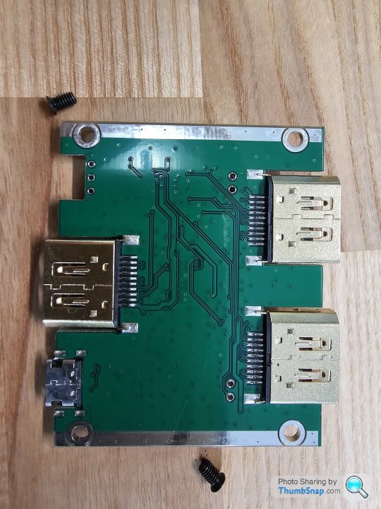
Annoyingly I had one in bits and took some pictures and can't find them, so I need to unplug one and take another look.
I did try to find one with a remote to make this easy, but couldn't find one. Then I figured I could simply disconnect the switch and put it on a longer cable, but it's on the PCB directly.
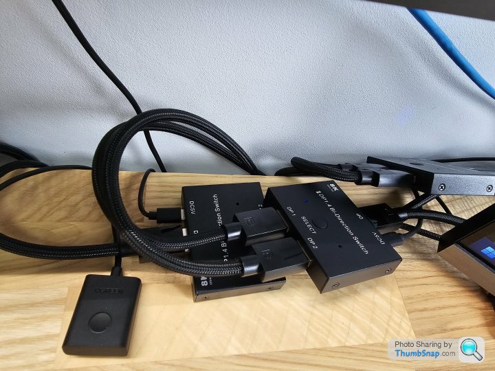
This is the setup, three of these boxes, you can see how there isn't an orientation that works because of the way the wires come out and the fact that there are three of them.
I think the options are to mount them under the desk top where they can't be seen. Install them wall mounted with some 90 degree Display Port adaptors to get the wires out of the way of each other. OR mess with the switch. Neither of the first two options really work for me, so the last one is what I'm aiming for.
I think the options are to mount them under the desk top where they can't be seen. Install them wall mounted with some 90 degree Display Port adaptors to get the wires out of the way of each other. OR mess with the switch. Neither of the first two options really work for me, so the last one is what I'm aiming for.
I found a switch that looks similar and it might be this one:
https://cpc.farnell.com/alps/skhhaka010/switch-tac...
and its datasheet shows this circuit diagram:
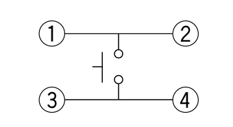
https://cpc.farnell.com/alps/skhhaka010/switch-tac...
and its datasheet shows this circuit diagram:
Mr Pointy said:
You can test that with a bit of wire with the ends stripped now the switch is out. Just donk the wire across 1& 3 & it might switch.
Well I put it all back once I had the pictures, but it's easy enough to open it again, so I guess I'll try that and see, What's the worst that can happen?It's not the end of the world of I fry one of the boxes, they're only£20, they're just a pain because they seem to only be available on a slow boat from China.
If that works it'll be pretty simple to get it all working I reckon.
Gassing Station | Computers, Gadgets & Stuff | Top of Page | What's New | My Stuff