FRONT FAN ISSUE
Discussion
Hello. The problem is one of the two fans has stopped. But the cause is strange. Have 12.8v on both pink cables, good neg on both blacks, swap plugs over and fan works. Did some more testing and found for some reason i now have around 75 ohms on one pink wire which is causing the fault. Does anyone have a diagram of where the 2 pink wires go to. The bible just shows 1 wire going to block E. Kind regards, Dave.
Have you given the plug/sockets a good clean as they are the usual problem?
Otherwise the schematic is here:
http://www.bertram-hill.com/cooling-fans-schematic...
Otherwise the schematic is here:
http://www.bertram-hill.com/cooling-fans-schematic...
Hi/, thanks for that. I have that diagram for single fan system but cannot find how TVR wired in the second fan. Mines Jan 96my,but probably built mid 95. 40A fuse bottom left and fan relay top left. 98my have 2 relays, one for each fan. Is there a wiring mod behind the fuse board? 75 ohm to ground indicates slight compression short on one of the pink wires but not low enough to pop fuse. Kind regards.
Am hoping that the following topic solves the problem, read every post as most of them contain something worth noting
https://www.pistonheads.com/gassing/topic.asp?h=0&...
https://www.pistonheads.com/gassing/topic.asp?h=0&...
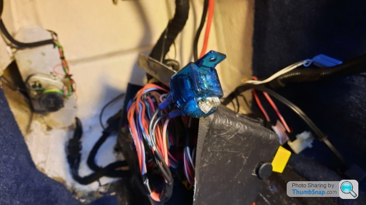
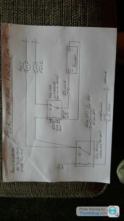
Great info, thanks. Did some more investigating this morning and now know that my 96my, probably built mid 95 has the 1 yellow relay top left to control both fans but are separately fused. The fan that works is via the 40A fuse, bottom left. The other fan[not working] is fed via an inline fuse 25A wired to the pos on battery. There is another wire on the neg post and they both go behind the fuse board. Changed relay, checked fuse.Looks like fuse board is coming out. Thanks for help. Will post what i find. Regards.
Cheers. Done all that this morning. Re terminated all connections in footwell and no joy. When fans activate i have 13.8 volts on each pink wire at front, both black negs are excellent 0.1 ohms. Changed relays and fuses. Swapped plugs at fans over and other fan kicks in so fans ok. Did some more testing and found the 40A fuse and yellow relay powers both fans[remove 40A fuse and relay and i lose 13.8V at each fan]. The TVR bodge uses the inline 25A fuse for only 1 fan[remove that fuse and i lose 13.8V to one fan connector, the circuit that has the fault]. Also i joined the two pink wires at fan plug and both fans work fine. So after more head scratching i think it has something to do with current draw because the voltage are ok, negs ok, all components and plugs ok. Sadly i cannot measure the amps at the plug as Fluke only goes to 10A DC, it would pop the meter fuse. Sadly no diagrams exist so next is fuse board out. Cheers, all the best.
Hi ,I think its the standard TVR mod carried out on 500s between 94 and 97 with 1 40A fuse and 1 yellow relay[top left]for twin fan radiators. 98 models onwards have 2 relays and 2 fuses. The fans have worked fine for 17 years only now the fan with the 25A inline fuse won't spin the motor even though the plug has 13.8 volts when the circuit is activated by the otter switch in swirl tank[swap plugs over and fan works]. That's why i think its current related as that's what makes it spin. Regards.
As said above measuring open circuit voltages can be misleading. Maybe measuring resistance ( on low Ohms range) from the faulty fan connection back is the best option, its surprising how high a resistance a dirty contact on the fuse connections, relay socket or even the relay/fuse block tags can produce.
DVR V8 said:
Thanks. Hope this is useful to anyone who wants to know how TVR wired in fan 2 up to 1998. All the best to everyone and have a great year. Dave.
I'm not convinced that is a TVR system.The early ones I have seen and the Steve Heath wiring diagrams just have the one relay supplying both fans.
Steve
Gassing Station | Griffith | Top of Page | What's New | My Stuff


