Wiring instructions for fuse22 switch
Discussion


I have the following remote switch, but no wiring instructions. Does anyone have a diagram or a simple set of instructions (for dummies) they could share?
http://www.maplin.co.uk/single-channel-wireless-re...
Many thanks
http://www.maplin.co.uk/single-channel-wireless-re...
Many thanks
you will have to make a small hole in the casing for the wires to exit,
I would use three different coloured wires, red for positive black for the earth and alternative colour for the switch wire,
starting from the right connection
1. +24v leave this on empty,
2. +12v red wire to here about 12 inches long also add in a bridging wire 3 inches long going to the middle connection on the other block of connections labelled com,
3, GND black wire to here with ring terminal again 12 inches long for the earth, the ring terminal can usually be connected to the mounting bolt securing the fuse box,
4 on the connection set of block to the left labelled NC connect the other colour wire 12 inches long this is the switch wire,
5. leave the NO one empty as well
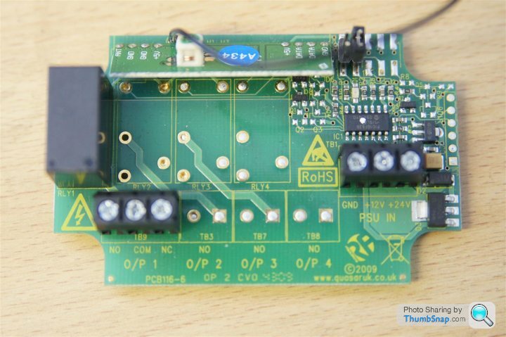
as you look at the picture the top right has two set of raised pins with black bridge out blocks remove the left hand one as shown removed in the image
the red positive has to go to the power feed for fuse 22, this is the connection closest to the brown relay, the switch wire goes to the other side, any problems just give me a call and I will talk you through it,
I would use three different coloured wires, red for positive black for the earth and alternative colour for the switch wire,
starting from the right connection
1. +24v leave this on empty,
2. +12v red wire to here about 12 inches long also add in a bridging wire 3 inches long going to the middle connection on the other block of connections labelled com,
3, GND black wire to here with ring terminal again 12 inches long for the earth, the ring terminal can usually be connected to the mounting bolt securing the fuse box,
4 on the connection set of block to the left labelled NC connect the other colour wire 12 inches long this is the switch wire,
5. leave the NO one empty as well
as you look at the picture the top right has two set of raised pins with black bridge out blocks remove the left hand one as shown removed in the image
the red positive has to go to the power feed for fuse 22, this is the connection closest to the brown relay, the switch wire goes to the other side, any problems just give me a call and I will talk you through it,
RichV12 said:
Is this to a point just another "sport" button though?
its purely for the exhaust valves so more audible than anything performance, rather than just removing fuse 22 this sits in its place giving the driver the choice louder or quieter in the lower rev range I think it is better than a hard wired switch as much cheaper, can be easily removed in minutes returning the car to as built, and can be completely a diy job, rick-derby- said:
you will have to make a small hole in the casing for the wires to exit,
I would use three different coloured wires, red for positive black for the earth and alternative colour for the switch wire,
starting from the right connection
1. +24v leave this on empty,
2. +12v red wire to here about 12 inches long also add in a bridging wire 3 inches long going to the middle connection on the other block of connections labelled com,
3, GND black wire to here with ring terminal again 12 inches long for the earth, the ring terminal can usually be connected to the mounting bolt securing the fuse box,
4 on the connection set of block to the left labelled NC connect the other colour wire 12 inches long this is the switch wire,
5. leave the NO one empty as well
as you look at the picture the top right has two set of raised pins with black bridge out blocks remove the left hand one as shown removed in the image
the red positive has to go to the power feed for fuse 22, this is the connection closest to the brown relay, the switch wire goes to the other side, any problems just give me a call and I will talk you through it,
Rick,I would use three different coloured wires, red for positive black for the earth and alternative colour for the switch wire,
starting from the right connection
1. +24v leave this on empty,
2. +12v red wire to here about 12 inches long also add in a bridging wire 3 inches long going to the middle connection on the other block of connections labelled com,
3, GND black wire to here with ring terminal again 12 inches long for the earth, the ring terminal can usually be connected to the mounting bolt securing the fuse box,
4 on the connection set of block to the left labelled NC connect the other colour wire 12 inches long this is the switch wire,
5. leave the NO one empty as well
as you look at the picture the top right has two set of raised pins with black bridge out blocks remove the left hand one as shown removed in the image
the red positive has to go to the power feed for fuse 22, this is the connection closest to the brown relay, the switch wire goes to the other side, any problems just give me a call and I will talk you through it,
1) How do you recommend attaching the wires in the fusebox? i.e. where the red/other wires attach to where the fuse would have been?
2) Re 1) which side does the power (+12v) wire go to (the side towards the centre of the fusebox or towards the outer edge of the fusebox)?
3) Not clear about the bridge-out blocks -- looking at the picture there appear to be two rows of pins (upper and lower), with 5 in each, which ones are bridged exactly?
Thanks!
Edited by ockhamsrazor on Tuesday 17th May 20:14
Hi Rick - thanks for the instructions. I wired it up as explained. However, although the relay clicks when the remote is operated, it doesn't seem to make any difference to the flaps which are always closed (i.e., their default position). Is it possible that the relay is shot? I've no feel for how reliable these components are.
the affect is not immediate as the vacuum has to build or return to normal atmospheric pressure, so there is a transition period, to test run the car until normal operating temperature, then blip the throttle up to about 3000 revs three or four times listening to the tone, then press the switch do the same again as you get to the fourth rev you should have a difference,
OK, after much trial and error, I've discovered that you need to remove the bridge connector from BOTH sets of pins on the PCB. Otherwise, the switch only opens briefly before closing again. With all the pins disconnected, it stays open (or closed) until operated again. I connected it up to one of the boot lights to work out its functionality.
Gassing Station | Aston Martin | Top of Page | What's New | My Stuff