Heater Amp Input Signal
Discussion
Afternoon all.
Can anyone tell me what the Pulse Width Modulation signal coming into the heater amplifier should look like? I still can't get my interior fans to run unless I short-out the wires at the hearer amp connector at which point it will happily run at full power.
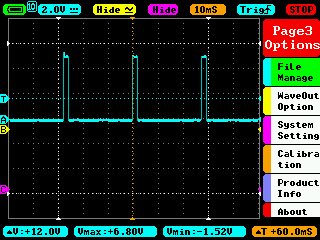
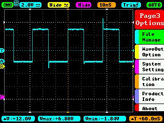
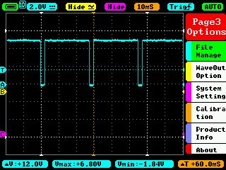
My PWM signal from the dash ECU looks like the below traces (at typ 10%, 50% & 90% fan switch levels) but I don't know if it's meant to be going between 0V and 12V (not 7V as below)?


The heater amp and dash ECU have both been to Jody for checking and the plug is fine (tight, no melting etc) so I'm a bit stumped why I still can't get the fans to run.
Thanks! Matt
Can anyone tell me what the Pulse Width Modulation signal coming into the heater amplifier should look like? I still can't get my interior fans to run unless I short-out the wires at the hearer amp connector at which point it will happily run at full power.
My PWM signal from the dash ECU looks like the below traces (at typ 10%, 50% & 90% fan switch levels) but I don't know if it's meant to be going between 0V and 12V (not 7V as below)?


The heater amp and dash ECU have both been to Jody for checking and the plug is fine (tight, no melting etc) so I'm a bit stumped why I still can't get the fans to run.
Thanks! Matt
Interesting to know, thanks.
I don't seem to have any signal on pin 3 (difficult to measure when all connected up in the footwell, but pretty sure).
I noticed that the PWM input signal reads differently when the amp circuit is connected compared to the traces above which were taken when the heater amp wasn't connected.
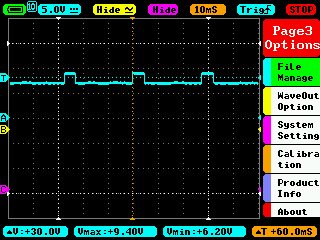
The input trace with the amp circuit connected looks like this, alternating between +6.2V and +9.4V (this is for a low fan speed on the switch):

Don't know if that's what it is meant to look like or not?
Looks like I'm just going to have to give up and get one of the specialists to try a different amp circuit and see if that fixes it.
Huummmm....
I don't seem to have any signal on pin 3 (difficult to measure when all connected up in the footwell, but pretty sure).
I noticed that the PWM input signal reads differently when the amp circuit is connected compared to the traces above which were taken when the heater amp wasn't connected.
The input trace with the amp circuit connected looks like this, alternating between +6.2V and +9.4V (this is for a low fan speed on the switch):

Don't know if that's what it is meant to look like or not?
Looks like I'm just going to have to give up and get one of the specialists to try a different amp circuit and see if that fixes it.
Huummmm....
MK_tamora said:
Have you got 12V (ignition switched) on pin 1 of the connector? Is the connector on the loom OK?
I'm in MK if you want to come over and borrow my amp.
Cheers
Nick
Yes, I have correct ignition live and ground on those leads. The connector on the loom is fine too. It needs to go in to someone for MOT & service so I'll get them to have a look. Thanks for the offer though (I'm in High Wycombe so not too far).I'm in MK if you want to come over and borrow my amp.
Cheers
Nick
Gassing Station | Tamora, T350 & Sagaris | Top of Page | What's New | My Stuff


