Technical question (afr/ltft/map) with engine modification
Discussion


TLDR: if the air fuel mixture is showing correct, why would the long term fuel trim be high?
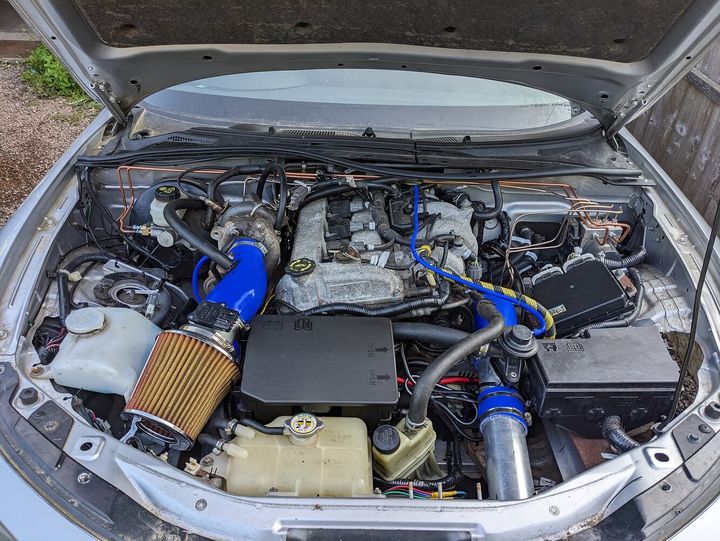
The long version of the above is, I am still somewhat of a noob at this but it's been a learning process all the way. I have finally finished an engine swap, a Mazda 2.3l turbo into my MK3 mx5, road legal here in the UK passing it's MOT (this includes a legit emissions test)
I have had to do several modifications to get it to fit, including custom intake/intercooler and top mounted turbo with a custom exhaust manifold with custom downpipe. ECU is stock from the donor car from which the engine came from.
Working on getting this working better I have looked at some of the readings from the ECU and got some questions.
The ECU is showing the correct AFR but it's reading +20% on the long term fuel trim, not enough to set of the engine management light but looking to get it resolved as it's not far from CEL.
Now this is my rookie mind at work here but if the mass air flow is showing the same amount of air and the afr is showing as desired, shouldn't the fuel rate be as expected too instead of +20%?
With the custom downpipe, due to the space restrictions I wouldn't say it's an optimised flow and the first O2 sensor is in a different location than the stock, Would this potentially be giving a changed reading? (bearing in mind the MOT emissions test was green)
With the intake changed, the stock intercooler was top mounted and so have had to make it front mounted now, this will have the better performance from less heat soak, would a cooler intake also have an effect here? While the air is cooler and probably denser the amount of air would be the same, but would this change the burn characteristics to account for different afr-ltft readings?
The caveat here though... I was far too much of a rookie when I first started to do this project that I don't know what the readings where when it was in the donor vehicle as I didn't think to check this before I pulled the engine
element118 said:
TLDR: if the air fuel mixture is showing correct, why would the long term fuel trim be high?
If it's running at the correct AFR with a fuel trim then you'd have to assume that the trim was correcting an inaccuracy in the base calibration. That is the purpose of the trim, after all.The purpose of the long term fuel trim in the simplest terms is to account for tolerances and aging of the engine vs the the "perfect" model that the ECU calibration is based around. To end up with a lot of trim in there are a few possibilities:
1: The fuel mass delivered by the injectors is significantly different to that which the ECU expects it to be for a given pulse width. This can be due to injector aging, base fuel pressure (especially if PFI), worn high pressure fuel pump drive or incorrect HPF timing (if DI), poorly calibrated injector voltage compensation (or the injectors are powered from a feed different to the ECU which is lower than the ECU voltage).
2) The VE of the engine is significantly different to the model in the area / condition which is considered valid for trim. This can be due to changes in the exhaust manifold, inlet manifold, throttle body/butterfly area or due to an air leak.
3) If the vehicle uses an air mass meter to measure the amount of inducted air mass then this can be providing an inaccurate reading at low air flow states due to the flow straightening grills being removed, some sort of cone type air filter very close to the air mass meter, turbulent flow into/around the air mass meter (e.g. recirculating BOV or similar plumbed into the airfilter just upstream of the AMM) or just because of a faling AMM.
4) Lambda aging or damage, or the wrong Lambda resulting in the reported Lambda (AFR) reading being incorrect.
As a starter for ten smoke test it to make sure there isn't a leak on the inlet side of the engine, make sure you have a sensible distance between the AMM/MAF and the filter/turbo inlet, check the base fuel pressure is correct if PFI and test the injectors to ensure flow is very similar across all of them. If the Lambda sensor is old/unknown and of a wideband type then fit a new one.
Really appreciate the input there.
I have made a poor man's smoke tester that wasn't too good, have now got a better one and plan to do that tomorrow on the intake and exhaust.
The injectors could be an issue here, it's an absolute nightmare to get to them, my plan here is to eliminate other possibilities before that. Saying that I will check the injector ground as this is something I initially forgot when I tried to start the engine for the first time - slim chance but may have a bit of corrosion, this is an easy check and if this is causing a voltage issue it's an easy fix.
I'm not familiar with the term VE? (Or at least I have not come across the abbreviation before) can you clarify please?
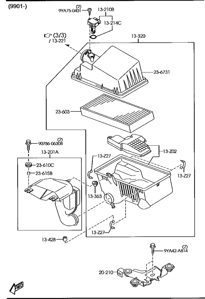
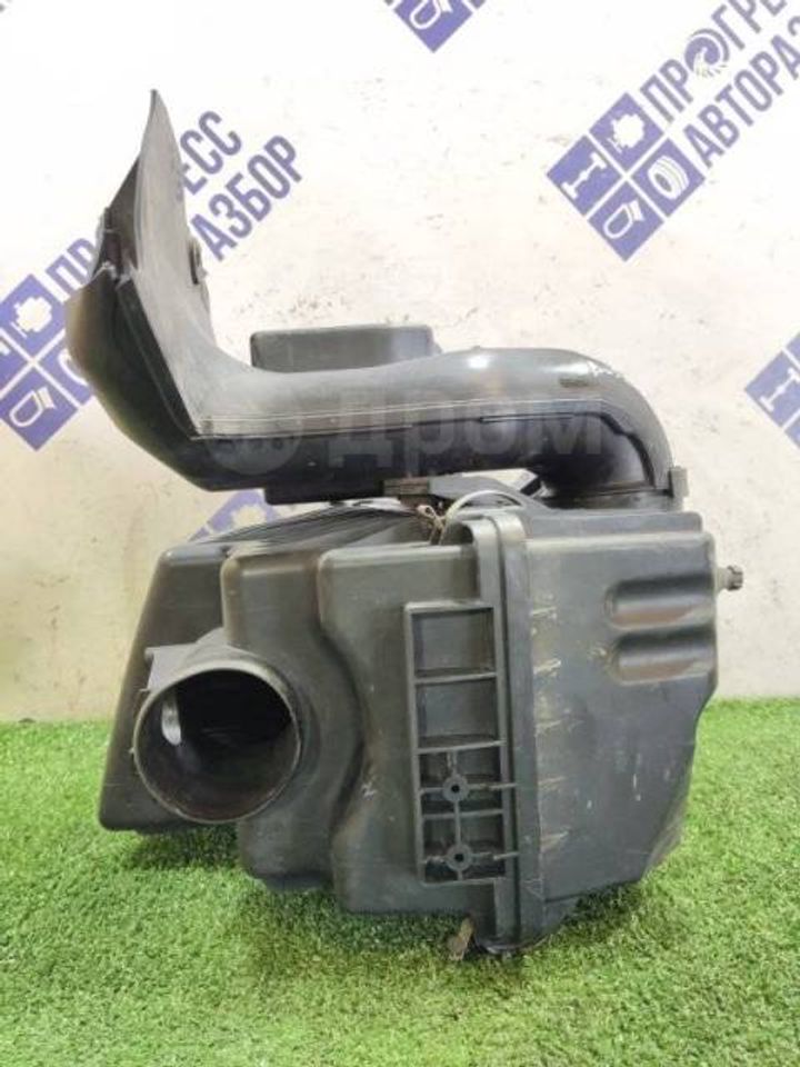
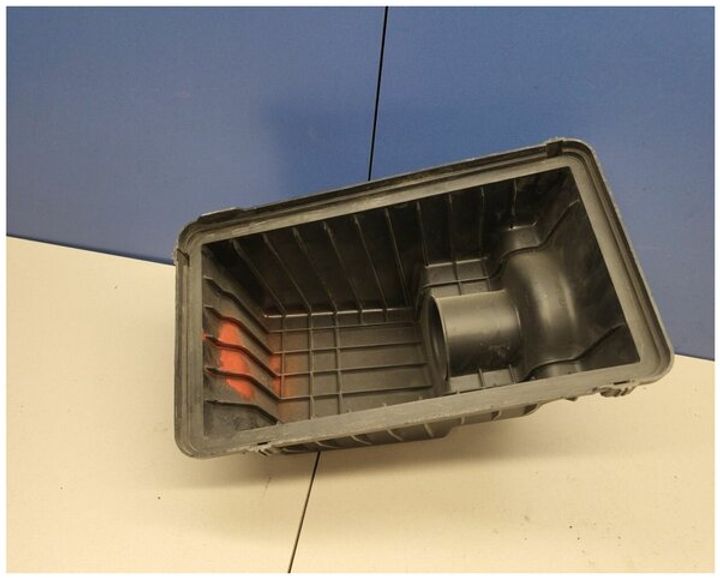
As to the MAF, I took another look at the original location, it's actually coming of the air filter, it had no grid fins, it's got the same diameter pipe, approx same length pipe too, re examining this i doubt there is too much difference but maybe someone can chime in here (see pictures)
The distance to the turbo inlet is shorter compared to OE but the overallmintake length is longer after the turbo , the bov recirculation is actually a fair bit different in location and orientation, the original had it facing into the turbo where as I got it 90 degrees to the turbo, I would assume though with the turbo still spooled up, it would most likely suck the air towards it more than blow out the opposite way back to the MAF. The issue here really was mostly available space, but tried to keep everything as far from the MAF as I could
I also swapped the MAF sensor for a known good one and didn't change anything.
The lambda sensor I believe to be good, I have had a failing sensor before and this triggers a CEL, could the sensor be bad and not give a CEL?
I have made a poor man's smoke tester that wasn't too good, have now got a better one and plan to do that tomorrow on the intake and exhaust.
The injectors could be an issue here, it's an absolute nightmare to get to them, my plan here is to eliminate other possibilities before that. Saying that I will check the injector ground as this is something I initially forgot when I tried to start the engine for the first time - slim chance but may have a bit of corrosion, this is an easy check and if this is causing a voltage issue it's an easy fix.
I'm not familiar with the term VE? (Or at least I have not come across the abbreviation before) can you clarify please?
As to the MAF, I took another look at the original location, it's actually coming of the air filter, it had no grid fins, it's got the same diameter pipe, approx same length pipe too, re examining this i doubt there is too much difference but maybe someone can chime in here (see pictures)
The distance to the turbo inlet is shorter compared to OE but the overallmintake length is longer after the turbo , the bov recirculation is actually a fair bit different in location and orientation, the original had it facing into the turbo where as I got it 90 degrees to the turbo, I would assume though with the turbo still spooled up, it would most likely suck the air towards it more than blow out the opposite way back to the MAF. The issue here really was mostly available space, but tried to keep everything as far from the MAF as I could
I also swapped the MAF sensor for a known good one and didn't change anything.
The lambda sensor I believe to be good, I have had a failing sensor before and this triggers a CEL, could the sensor be bad and not give a CEL?
Just face reality.
You have altered quite a bit from factory.
The ecu will require re-tuning to suit your new configuration if you want all such trims to be closer to zero.
Either that, or restore as much as you can, to identical to factory.
From air inlet, to exhaust tip
Otherwise there is no reason you should expect it to be behaving, and have fuel or any trims as per OEM, when the installation has changed a lot from OEM.
Or just be happy with it as it is, trims and all.
I assumed I will possibly need to tune, I am getting some software and a guy who has said they are happy to help tune this, however if there are underlying problems that needs addressing before this, no point tuning until they are done.
After the comments here, one thing I am looking to do is re-design the short intake from the filter to the turbo, see what can be done better. Either make a new pipe and weld the bov recirculation in at a better angle/location or 3d print using a high temperature carbon fiber filament.
On a side note, the intake manifold/plenum and the throttle body are stock so can rule them out being an issue
It's running lean, assuming that the ECU is correct for the engine, and the injectors and sensors are all correct for the engine/ECU (in other words you've pulled the complete kit across from the donor) then you have an air leak.
Bottle of brake cleaner or easy start, start spraying around the inlet system and see if the revs change. In an ideal world be watching the real time fuel trims while your doing it, you should see it richen up when you find the leak.
There's a high chance around the rocker box area will be your bingo, the pcv set up, or rocker gasket, oil cap etc. it's sucking air in somewhere. You will curse yourself if it turns out you've left a port disconnected without realising.
element118 said:
high temperature carbon fiber filament.
I've never heard of any carbon fibre that would tolerate exhaust temperatures. It's possible to 3d print metal, but it seems extremely unlikely you'd need to resort to that. I'm sure you'll find it is cheaper and easier to fabricate whatever pipework you're aiming for.wildoliver said:
It's running lean, assuming that the ECU is correct for the engine, and the injectors and sensors are all correct for the engine/ECU (in other words you've pulled the complete kit across from the donor) then you have an air leak.
Bottle of brake cleaner or easy start, start spraying around the inlet system and see if the revs change. In an ideal world be watching the real time fuel trims while your doing it, you should see it richen up when you find the leak.
There's a high chance around the rocker box area will be your bingo, the pcv set up, or rocker gasket, oil cap etc. it's sucking air in somewhere. You will curse yourself if it turns out you've left a port disconnected without realising.
Yep, everything was pulled over, ECU, injectors and sensors etc. will do both another smoke test and brake cleaner etc when I get a chance, the weather isn't looking great for a few daysBottle of brake cleaner or easy start, start spraying around the inlet system and see if the revs change. In an ideal world be watching the real time fuel trims while your doing it, you should see it richen up when you find the leak.
There's a high chance around the rocker box area will be your bingo, the pcv set up, or rocker gasket, oil cap etc. it's sucking air in somewhere. You will curse yourself if it turns out you've left a port disconnected without realising.
GreenV8S said:
I've never heard of any carbon fibre that would tolerate exhaust temperatures. It's possible to 3d print metal, but it seems extremely unlikely you'd need to resort to that. I'm sure you'll find it is cheaper and easier to fabricate whatever pipework you're aiming for.
Yep your right, exhaust is a no go, but it's on the intake side, so looking at engine bay temperature, this stuffs melting point is 240c but will go soft before that, should stand up to 100c - if the intake is hotter than that in the engine bay then other cooling solution will be needed such as vents etc, it's a daily driver won't be hours on a race track element118 said:
I assumed I will possibly need to tune, I am getting some software and a guy who has said they are happy to help tune this, however if there are underlying problems that needs addressing before this, no point tuning until they are done.
After the comments here, one thing I am looking to do is re-design the short intake from the filter to the turbo, see what can be done better. Either make a new pipe and weld the bov recirculation in at a better angle/location or 3d print using a high temperature carbon fiber filament.
On a side note, the intake manifold/plenum and the throttle body are stock so can rule them out being an issue
It could be a problem, or it could simply be you've changed everything from standard.After the comments here, one thing I am looking to do is re-design the short intake from the filter to the turbo, see what can be done better. Either make a new pipe and weld the bov recirculation in at a better angle/location or 3d print using a high temperature carbon fiber filament.
On a side note, the intake manifold/plenum and the throttle body are stock so can rule them out being an issue
Where exactly was the MAF located as standard ? any pics ? and are you using the same housing for the MAF ?
Close to the turbo inlet can cause lots of turbulence within the MAF, messing things up. MAF needs smooth air.
OP smoke test it, if you can't smoke test it then take it somewhere that can. This will absolutely rule out any air leaks or similar you may have going on.
Once you've done that I would look at how your are delivering air to the MAF, the standard airbox has a large flow straightening protrusion into the airbox before air passes into the MAF. Are you also absolutely, 100%, without fail confident that the ID of the pipe the MAF is in is the same as the original MAF tube? Even a small difference here will have a measureable impact on the MAF calibration.
Once you've done that I would look at how your are delivering air to the MAF, the standard airbox has a large flow straightening protrusion into the airbox before air passes into the MAF. Are you also absolutely, 100%, without fail confident that the ID of the pipe the MAF is in is the same as the original MAF tube? Even a small difference here will have a measureable impact on the MAF calibration.
I was able to do a smoke test today, indeed I have found another one, stupidly hard place to get to but it looks like its fixed.
After I done the test again, found another small one, this time it was an oversight/design flaw I had an adapter for the BOV, the gasket for which went over the grub screws that held it in place and leaked around there, have ordered some rubber gasket material and will be making a custom one to fit, hopefully this will resolve the leaks and ultimately fix the LTFT.
this new smoke machine I am using way better than the first, working a treat now
Gassing Station | Engines & Drivetrain | Top of Page | What's New | My Stuff