Does anyone remember / know about this engine.......
Discussion
Many moons ago on BBC Tomorrows World a rotary style engine was featured that was based on two rings, one of cylinders and one of pistons.
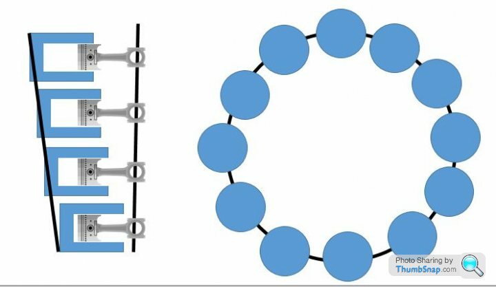
The rings were mounted on a central shaft and offset by I think 21 degrees. This had the resultant effect that when rotated the pistons effectively moved up an down in the cylinders but did not actual change direction due to the offset angle of the two hoops. i.e. the pistons were always moving in the same direction. Below is a very crude drawing to try an illustrate what I an describing.

I am trying to find out some detail of this engine, but as with many things that were on Tomorrows World it appears to have vanished.
Do my ramblings mean anything to anyone and if so do you know any more detail of this engine design?
The rings were mounted on a central shaft and offset by I think 21 degrees. This had the resultant effect that when rotated the pistons effectively moved up an down in the cylinders but did not actual change direction due to the offset angle of the two hoops. i.e. the pistons were always moving in the same direction. Below is a very crude drawing to try an illustrate what I an describing.

I am trying to find out some detail of this engine, but as with many things that were on Tomorrows World it appears to have vanished.
Do my ramblings mean anything to anyone and if so do you know any more detail of this engine design?
You're referring to an "Axial engine" of whwihc there are several types.
See the Wiki entry: https://en.wikipedia.org/wiki/Axial_engine
John
See the Wiki entry: https://en.wikipedia.org/wiki/Axial_engine
John
Thank you, looks similar, but I believe that this design still requires the piston to change direction. I am sure that variant I recall from 40 odd years ago, relied on the 'meshing' angle between the piston ring and the cylinder ring, that the pistons did not physically change direction. they moved in and out due to the angle around which the ring rotated. I think I might have to try and mock something up to see if I am remembering correctly or if I am barking up the wrong tree.
Due to the angle between the cylinders and pistons the rings rotate and as a result they move together and apart which provides the in and out movement of the piston. The piston does not stop and change direction at the end of each stroke it is rotating with the ring and is in effect always travelling in the same direction.
TVR_Coley said:
Due to the angle between the cylinders and pistons the rings rotate and as a result they move together and apart which provides the in and out movement of the piston. The piston does not stop and change direction at the end of each stroke it is rotating with the ring and is in effect always travelling in the same direction.
Still a bit confused by your description; there is clearly reciprocating motion between the piston and the cylinder, so either one of them is stationary (w.r.t. the whole engine) and the other reciprocates, or they both have reciprocating motion. No part within the engine can have continuous motion in one direction.This is in part why I am keen to try and dig up the detail to refresh my memory on how it was set up.
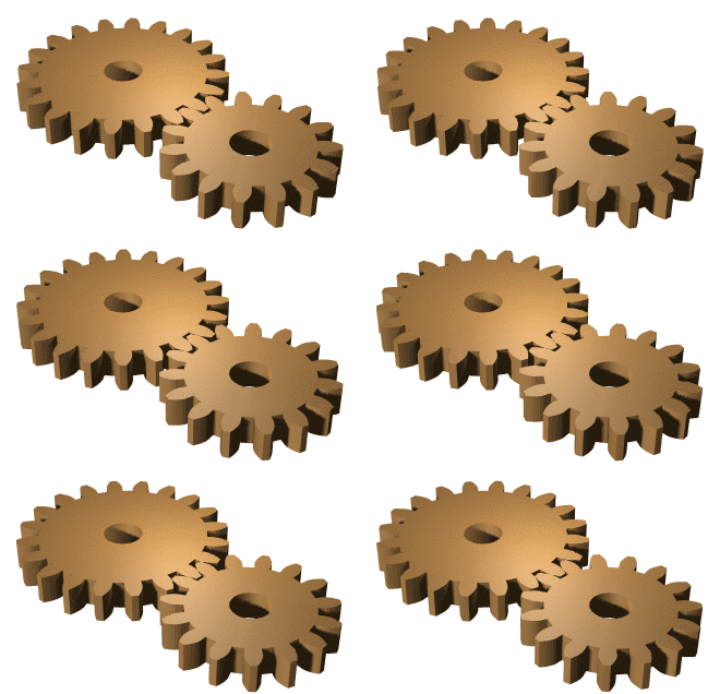
The closest analogy I can illustrate is If you think about two cogs wheel meshing together, where the teeth are the pistons and the gaps are the cylinders.
In the animation below the pistons (teeth) move in and out of the cylinders (gaps) but the teeth do not change direction to do this, it is the rotation that allows them to move in and out.

In the engine design I recall this is how it worked but the cogs were rotating around the same axis in a V of I think 21 degrees. So at the bottom of the V the piston was fully in the cylinder (at the top of the piston stroke) and the the top of the V where the rings were farthest apart the piston was at the bottom of the stroke.
The closest analogy I can illustrate is If you think about two cogs wheel meshing together, where the teeth are the pistons and the gaps are the cylinders.
In the animation below the pistons (teeth) move in and out of the cylinders (gaps) but the teeth do not change direction to do this, it is the rotation that allows them to move in and out.

In the engine design I recall this is how it worked but the cogs were rotating around the same axis in a V of I think 21 degrees. So at the bottom of the V the piston was fully in the cylinder (at the top of the piston stroke) and the the top of the V where the rings were farthest apart the piston was at the bottom of the stroke.
The Wookie said:
E-bmw said:
In answer to your actual question, no I don't.
However what you are talking about is basically a multi piston fixed swash pump but made into an engine.
This. It just looks like a fixed displacement rotary hydraulic pump with conrods However what you are talking about is basically a multi piston fixed swash pump but made into an engine.
https://commons.m.wikimedia.org/wiki/File:Axialkol...
TVR_Coley said:
In the animation below the pistons (teeth) move in and out of the cylinders (gaps) but the teeth do not change direction to do this, it is the rotation that allows them to move in and out.
Connect a con rod to each tooth with a piston at the far end and constrain the pistons to stay aligned with a fixed axis and you have a conventional engine. The only way to avoid the change in direction is to have the axis of the cylinder parallel with the axis of the gear wheel, in which case there is no relative movement and you have a static arrangement of pistons and cylinders going round in a circle.really OLD tech.....Citroen have used this a a hydraulic pump since the 50's
https://www.youtube.com/watch?v=Ni-49tkO6t0
https://www.youtube.com/watch?v=Ni-49tkO6t0
Gassing Station | Engines & Drivetrain | Top of Page | What's New | My Stuff


