Testing the Meta M36 / M36T2 immobiliser
Discussion


I know that a few people have had issues with their Meta M36 / M36T2 immobiliser units and watching the guy repairing his salvaged Cerbera having trouble with his made me remember to post up how to test the units and a few helpful hints for anyone else who has problems in the future
1. Basic wiring
Even though all of the wires on the immobiliser are black, and deliberately designed to be unidentifiable when they are trimmed (*the labelling is only at the very end of the wire and is removed when trimmed) it is still possible to identify the wires for testing
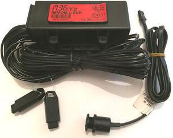
Meta unit and wiring diagram - this was grabbed from a Czech Skoda website so I don't think anyone will mind me sharing it
Meta unit
Wiring diagram
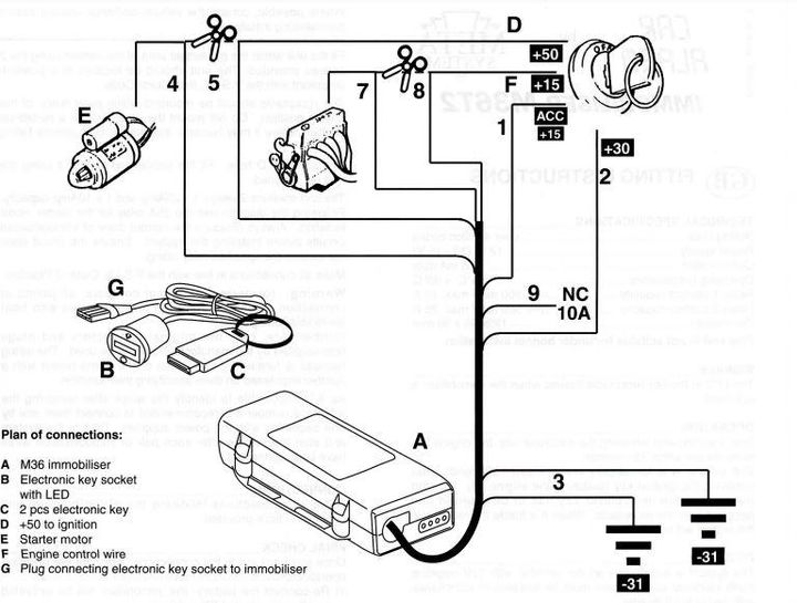
So basically the unit has 2 relays that when the immobiliser is enabled cut the connections between the starter motor and power (wires 4 [4NR] and 5 [5NR]) and the fuel system (wires 7 [7NR] and 8 [8NR])
When the immobiliser is disabled, these two relays are triggered and both connections are restored, allowing you to start the car
Constant power from the battery is provided on wire 2 [2NR] and there are two ground wires, both labelled wire 3 [NR3]
The last wire is wire 1 [NR1] which provides power to the ignition system
2. Identifying the wires
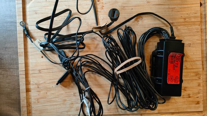
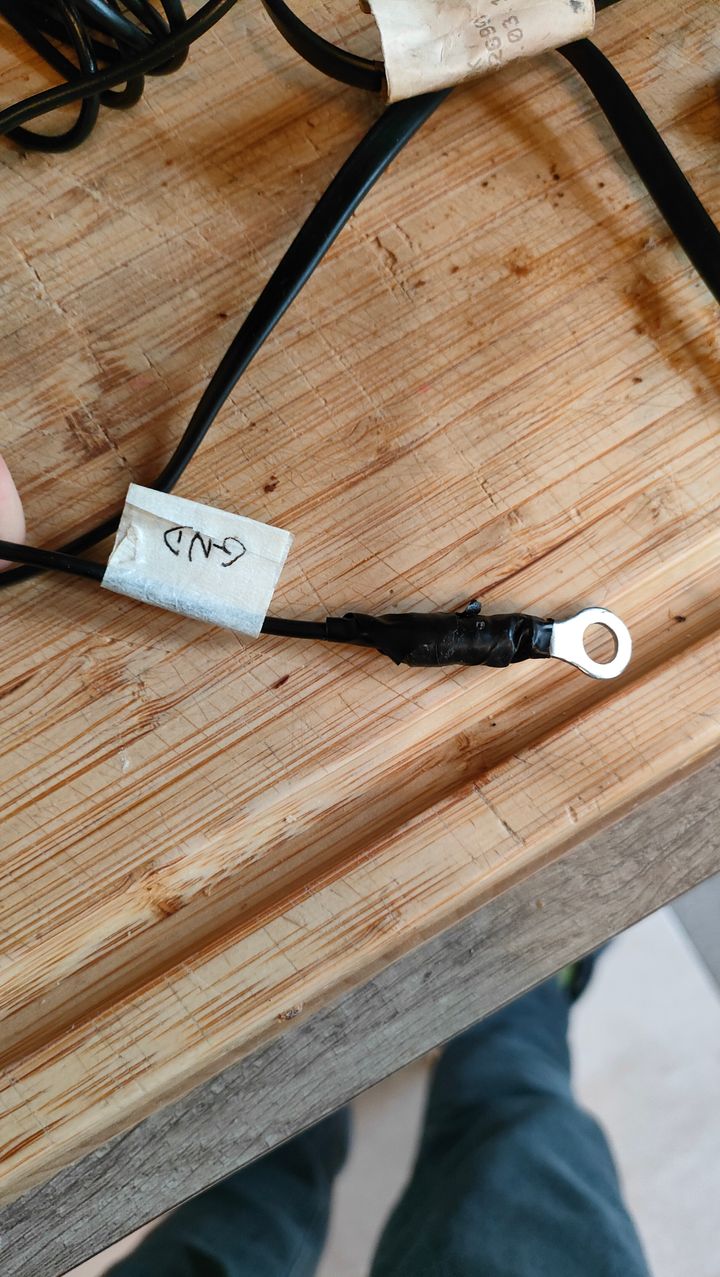
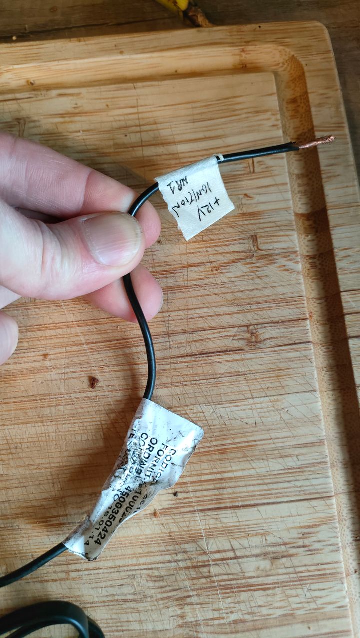
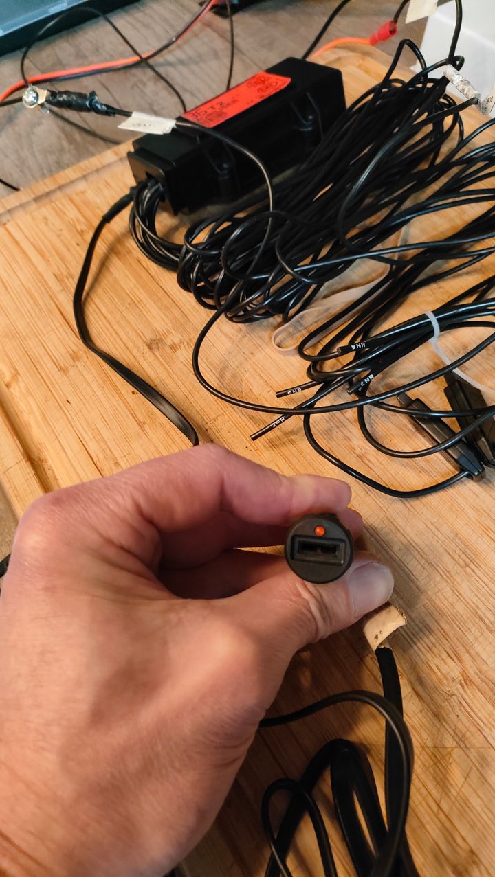
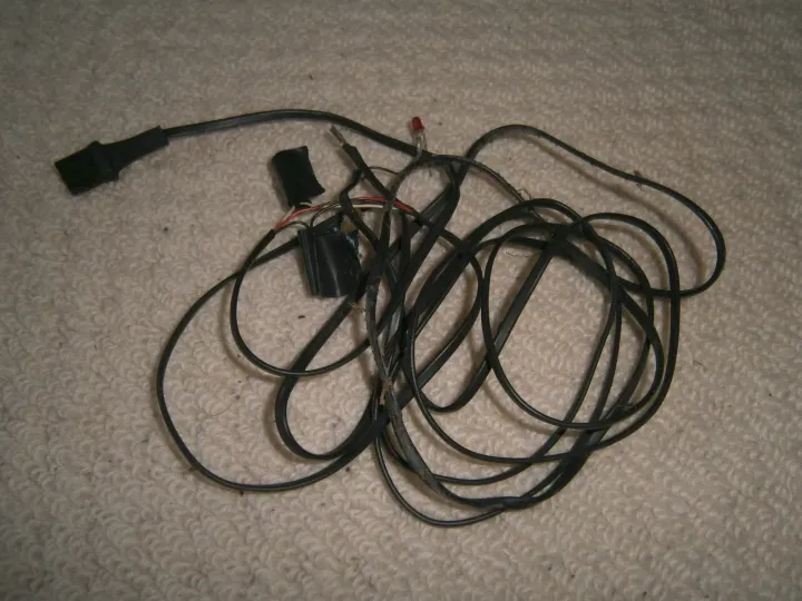
I bought a spare unit a while ago and decided to test this to find out how the wires are connected. This was the state of the wires when I got it (there is also a 4 pin socket that connects to the LED indicator and immobiliser fob socket):
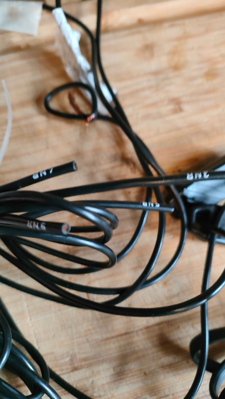
So we know that one of the cut wires is a Ground [3NR] and one of the uncut wires is a Ground labelled [3NR] so we can identify that pretty quickly (the big grounding hoop is also a bit of a give away )
)
One of the other wires is the +12V constant feed so we can check that by applying power to it (the relay wires are fine with this as they are not connected as this point) - handily again Meta labelled this wire with a big label which gave me a heads up to start with this one
3. Testing the unit
Now that we have power we can rig it up to a bench 12V power supply and test the unit
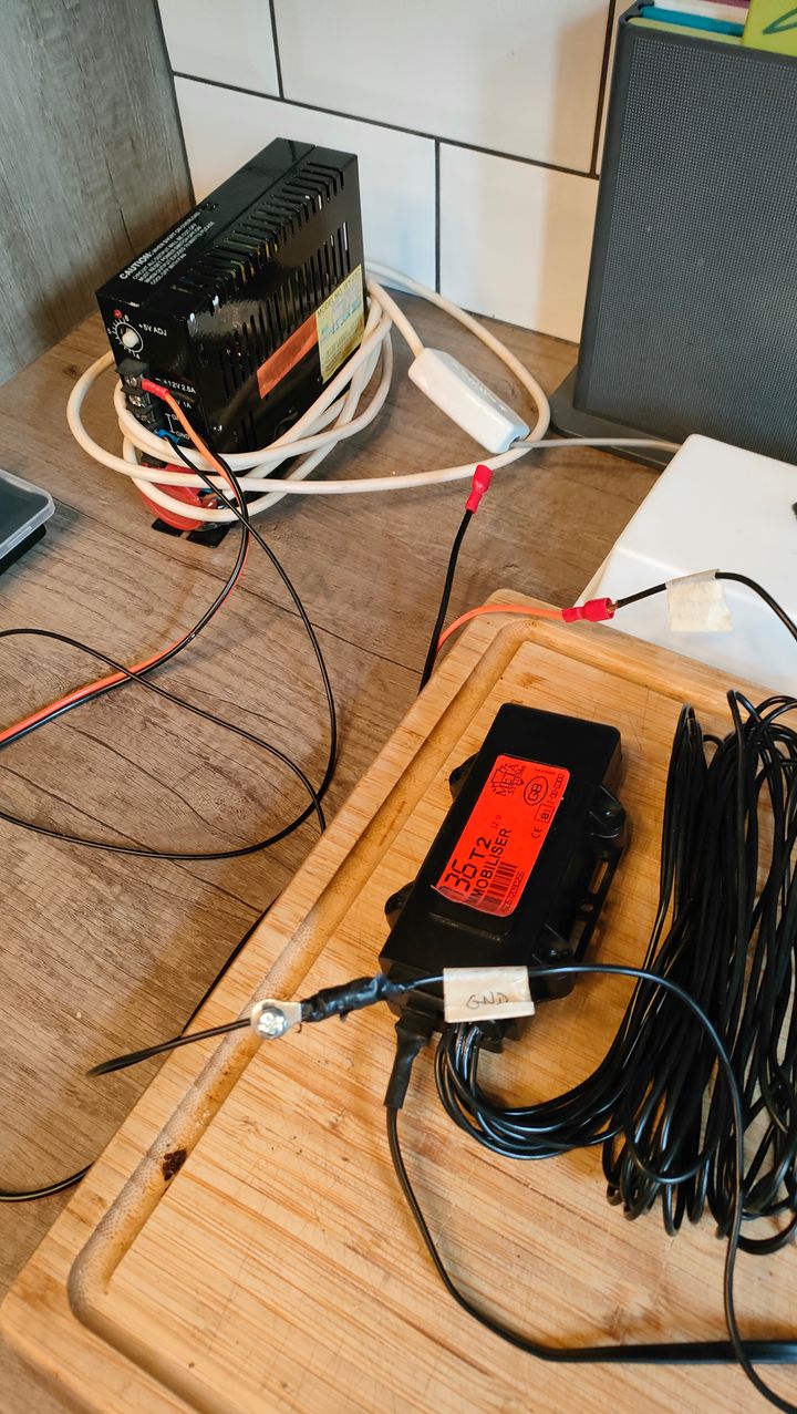
Plug in the 4 pin LED indicator / fob socket
and then apply power and test
As you can see from this short video we can disable the immobiliser with the fob, and then continuity test the wires to find the relay pairs (in this case only one)
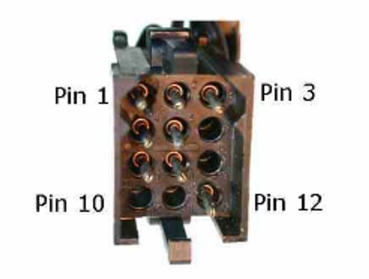
4. TVR connections
The TVR unit is connected by a 12 pin 3x4 connector which matches the pin numbers of the wires above, except that pin 12 is used for the second Ground [NR3]
Here's the connection from another document which I've not shared as it's not mine to share, but I think sharing a photo of a plug is fine
So I hope that's helpful to others in the future and at least you should be comfortably able to pull it out if it goes wrong, or bypass it by jumpering the relay wires if needed
1. Basic wiring
Even though all of the wires on the immobiliser are black, and deliberately designed to be unidentifiable when they are trimmed (*the labelling is only at the very end of the wire and is removed when trimmed) it is still possible to identify the wires for testing
Meta unit and wiring diagram - this was grabbed from a Czech Skoda website so I don't think anyone will mind me sharing it
Meta unit
Wiring diagram
So basically the unit has 2 relays that when the immobiliser is enabled cut the connections between the starter motor and power (wires 4 [4NR] and 5 [5NR]) and the fuel system (wires 7 [7NR] and 8 [8NR])
When the immobiliser is disabled, these two relays are triggered and both connections are restored, allowing you to start the car
Constant power from the battery is provided on wire 2 [2NR] and there are two ground wires, both labelled wire 3 [NR3]
The last wire is wire 1 [NR1] which provides power to the ignition system
2. Identifying the wires
I bought a spare unit a while ago and decided to test this to find out how the wires are connected. This was the state of the wires when I got it (there is also a 4 pin socket that connects to the LED indicator and immobiliser fob socket):
Uncut

3NR - GND
4NR - Starter In
5NR - Starter Out
9NR - N/C

Cut

1NR - Key positive x
2NR - Permanent +12V power supply (battery)
3NR - GND x
7NR - Fuel In x
8NR - Fuel Out x

4 pin socket

|---------|
| 1 2 3 4 |
 --\___/--

1 = GND
2 =
3 =
4 =
So we know that one of the cut wires is a Ground [3NR] and one of the uncut wires is a Ground labelled [3NR] so we can identify that pretty quickly (the big grounding hoop is also a bit of a give away
)One of the other wires is the +12V constant feed so we can check that by applying power to it (the relay wires are fine with this as they are not connected as this point) - handily again Meta labelled this wire with a big label which gave me a heads up to start with this one
3. Testing the unit
Now that we have power we can rig it up to a bench 12V power supply and test the unit
Plug in the 4 pin LED indicator / fob socket
and then apply power and test
As you can see from this short video we can disable the immobiliser with the fob, and then continuity test the wires to find the relay pairs (in this case only one)
4. TVR connections
The TVR unit is connected by a 12 pin 3x4 connector which matches the pin numbers of the wires above, except that pin 12 is used for the second Ground [NR3]
Here's the connection from another document which I've not shared as it's not mine to share, but I think sharing a photo of a plug is fine
So I hope that's helpful to others in the future and at least you should be comfortably able to pull it out if it goes wrong, or bypass it by jumpering the relay wires if needed

Thanks everyone and glad that this information is helpful
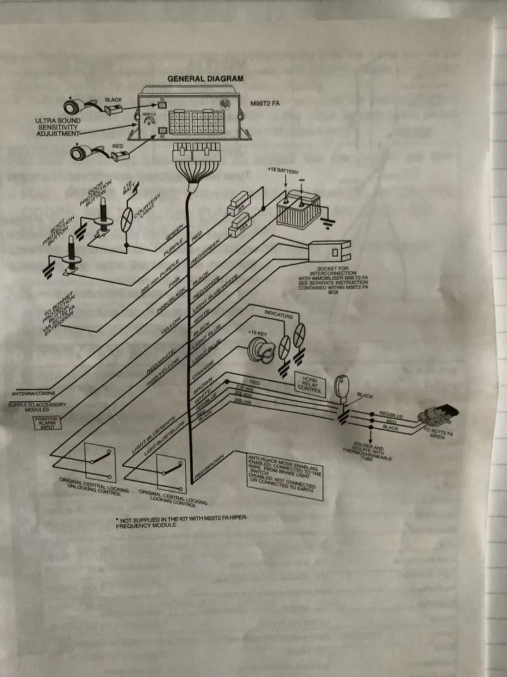
On the question of how everything else with the alarm is connected together, here's a handy diagram from the guys over on the Alfa Owners forum that shows how all the other parts of the system are connected together (the Alfa GTV shares the same alarm system).
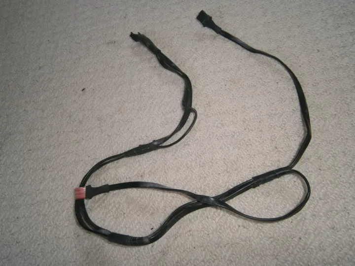
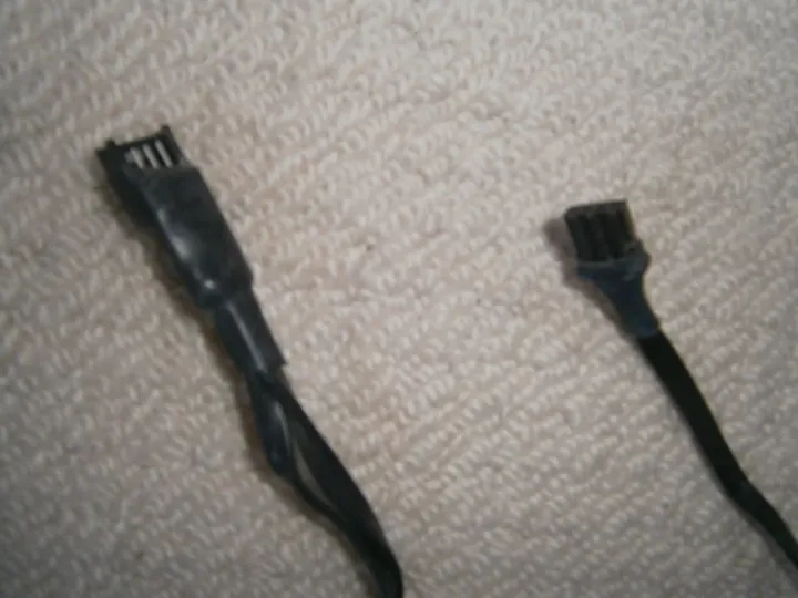
The immobiliser is connected in parallel with the alarm via the 4 pin socket using a cable like this (borrowed from an advert on eBay if anyone is after one)
The same with the LED
On the question of how everything else with the alarm is connected together, here's a handy diagram from the guys over on the Alfa Owners forum that shows how all the other parts of the system are connected together (the Alfa GTV shares the same alarm system).
The immobiliser is connected in parallel with the alarm via the 4 pin socket using a cable like this (borrowed from an advert on eBay if anyone is after one
)The same with the LED
Hi, first time poster, long time reader, all info is really useful.
I must confirm my intentions are not wanting to cause offence. I am sure all owners will very gratefully appreciate discreetness with this info, being that it is relevant to what are very desirable vehicles to certain individuals that sadly do indeed walk amongst us.
I’m sure an ‘old guard’ method of ownership proved than a PM for specific info for bypassing of any security would be greatly appreciated. I’m sure there must be the odd one still street parked in a built up area.
Please, please can this thread not wreck it for those of us that enjoy, cherish and value these vehicles.
Yes absolutely as above ^^^
Both of the wiring diagrams are already available on other public forums (there are links to them in the post) and this is really just a post about bring all of that together in one place for how the same system is implemented by TVR for the Cerbera
Carl over at Abacus Alarms has a wealth of information over on his site, and also sells immobiliser by-pass plugs, so I think there's no real pandora's box with the post to be honest
BTW one final tip - if you have all of the immobiliser wires cut and can't identify _any_ of the wires, then pin 1 on the 4 pin LED / fob socket connector is GND so you can find the 2 x 3NR GND connections by running a continuity test between the wires and this pin
Also, they should be the only two wires that continuity test to each other, as all of the rest are not directly connected (open [NO] for the two relays when power is off)
Edited by Juddder on Monday 10th March 16:17
I’ve contemplated removing the immobilizer (and the alarm) and just always having the car in a constant open/operable state.
Where I live, no one would ever work out how to get in, let alone be able to drive a manual right hand drive car. Mostly, they wouldn’t even get past the “what is it?” shock/awe.
Where I live, no one would ever work out how to get in, let alone be able to drive a manual right hand drive car. Mostly, they wouldn’t even get past the “what is it?” shock/awe.
Imran999 said:
I’ve contemplated removing the immobilizer (and the alarm) and just always having the car in a constant open/operable state.
Where I live, no one would ever work out how to get in, let alone be able to drive a manual right hand drive car. Mostly, they wouldn’t even get past the “what is it?” shock/awe.
I totally get this, and who would ever know? Not like insurance companies send round an immobiliser inspector each year Where I live, no one would ever work out how to get in, let alone be able to drive a manual right hand drive car. Mostly, they wouldn’t even get past the “what is it?” shock/awe.

I also considered this. But by buying a plug and play replacement system from Abacus, I didn't have to chase any wiring issues. The alarm being connected to remote locking may make it problematic.
I now have 2 flashing leds onboard my Griff, one for the immobiliser and a separate one for the alarm.
I now have 2 flashing leds onboard my Griff, one for the immobiliser and a separate one for the alarm.
Gassing Station | Cerbera | Top of Page | What's New | My Stuff