"Pulsating" brightnes on dash lights and external lights
Discussion


Folks, looking for a bit of advice.
I've got symptoms as described above. Recently happened, also noting that voltage value has recently made a 'step' change when viewed on dash. Volts used to be btwn 13.5 and 14V. Now, I've got 14.5V and sometimes more. I've checked volts at rear light and value is confirmed with a decent meter.
Would I be correct in assuming it's the alternator (or diode pack) failing that is giving me these symptoms. I'm thinking diode pack being responsible for 'pulsation' - if it was failing and not rectifying the A/C produced by the alternator??
Help appreciated.
Nick
Hello
It won't be a main diode failing, if a main diode fails by going short circuit it will then rapidly burn out to then being open circuit, open circuit diodes will lower the voltage rather than increase it
If one or more diodes of the diode trio that gives an output to the rotor plus battery warning light fails you will see a glowing or fully illuminated warning light and a lower voltage
When I was a lad the regulators on the market were designed to give 14 volts max, later regulators were designed to give 14.5 max
Voltages above 14.5 volts are caused by regulator failure
Polly Grigora said:
Hello
It won't be a main diode failing, if a main diode fails by going short circuit it will then rapidly burn out to then being open circuit, open circuit diodes will lower the voltage rather than increase it
If one or more diodes of the diode trio that gives an output to the rotor plus battery warning light fails you will see a glowing or fully illuminated warning light and a lower voltage
When I was a lad the regulators on the market were designed to give 14 volts max, later regulators were designed to give 14.5 max
Voltages above 14.5 volts are caused by regulator failure
PG, thanks for prompt reply...It won't be a main diode failing, if a main diode fails by going short circuit it will then rapidly burn out to then being open circuit, open circuit diodes will lower the voltage rather than increase it
If one or more diodes of the diode trio that gives an output to the rotor plus battery warning light fails you will see a glowing or fully illuminated warning light and a lower voltage
When I was a lad the regulators on the market were designed to give 14 volts max, later regulators were designed to give 14.5 max
Voltages above 14.5 volts are caused by regulator failure
So, I understand it's likely the regulator, rather than the rectification pack, failing - am I correct?
Would this cause the pilsation?
Cheers. Nick
Yes, you're on the case
New regulator will come with brush-box and brushes, if deciding to fit a new regulator/brush-box it would be good to check the slip-ring for wear once the failing regulator/brush-box has been removed as you will be able to get a finger in the square cut-out that the brush-box fits in through, 1 to 2mm slip-ring wear is ok, 3mm and above slip-ring wear requires attention as it will wear out sooner than later......
Insert digit into hole and use nail to gauge depth of slip-ring wear, obviously no use if you bite your nails
Coincidentally I had similar the other day. Started off with bad shunting on a light throttle and then noticed the charging was going up to over 16v. Stopped for 5 minutes restarted and shunting gone and charging from low 12 to low 14 volts. Drove ok the next day with stable charging.
Gremlin or something breaking down?
Gremlin or something breaking down?
Polly Grigora said:
Yes, you're on the case
New regulator will come with brush-box and brushes, if deciding to fit a new regulator/brush-box it would be good to check the slip-ring for wear once the failing regulator/brush-box has been removed as you will be able to get a finger in the square cut-out that the brush-box fits in through, 1 to 2mm slip-ring wear is ok, 3mm and above slip-ring wear requires attention as it will wear out sooner than later......
Insert digit into hole and use nail to gauge depth of slip-ring wear, obviously no use if you bite your nails
Morning PG!New regulator will come with brush-box and brushes, if deciding to fit a new regulator/brush-box it would be good to check the slip-ring for wear once the failing regulator/brush-box has been removed as you will be able to get a finger in the square cut-out that the brush-box fits in through, 1 to 2mm slip-ring wear is ok, 3mm and above slip-ring wear requires attention as it will wear out sooner than later......
Insert digit into hole and use nail to gauge depth of slip-ring wear, obviously no use if you bite your nails
Thanks for advice. OK, looks like Google is going to be my friend!
Nick
s6boy said:
Coincidentally I had similar the other day. Started off with bad shunting on a light throttle and then noticed the charging was going up to over 16v. Stopped for 5 minutes restarted and shunting gone and charging from low 12 to low 14 volts. Drove ok the next day with stable charging.
Gremlin or something breaking down?
Time to change the regulator, they don't fix themselves.Gremlin or something breaking down?
Every sensor on your engine is designed to work at around 12volts or just over, not 14.5 volt or more hence the poor running.
OK, Bit of an update.
I've got a replacement alternator from my local motor factors (Brand is "Apecs" - allegedly something above 'middle of the road') and it's now on the car.
Issue I have is that whilst voltage is stable, and engine runs fine, I don't get the "BATTERY" light ON when I turn the key to the first position. If I then disable the immobiliser using the button on the key, the oil pressure warning light comes on (previously nothing) until I crank the engine. The engine starts and runs fine. The immobiliser will not allow a 'start' until disabled. Indicated voltage on dash is between 13.2 and 14.0V.
I've heard of putting a diode into the D+ (small gauge wire) - should I do this?
The only electrical connections I disturbed were: Negative at battery before disconnecting original alternator, the main output terminal and the wire on the D+ terminal.
Any responses?
Nick
nawarne said:
OK, Bit of an update.
I've got a replacement alternator from my local motor factors (Brand is "Apecs" - allegedly something above 'middle of the road') and it's now on the car.
Issue I have is that whilst voltage is stable, and engine runs fine, I don't get the "BATTERY" light ON when I turn the key to the first position. If I then disable the immobiliser using the button on the key, the oil pressure warning light comes on (previously nothing) until I crank the engine. The engine starts and runs fine. The immobiliser will not allow a 'start' until disabled. Indicated voltage on dash is between 13.2 and 14.0V.
I've heard of putting a diode into the D+ (small gauge wire) - should I do this?
The only electrical connections I disturbed were: Negative at battery before disconnecting original alternator, the main output terminal and the wire on the D+ terminal.
Any responses?
Nick
Just to add, I do (very briefly) get the battery/ignition light ON when key goes to POS'N I....then blinks off!I've got a replacement alternator from my local motor factors (Brand is "Apecs" - allegedly something above 'middle of the road') and it's now on the car.
Issue I have is that whilst voltage is stable, and engine runs fine, I don't get the "BATTERY" light ON when I turn the key to the first position. If I then disable the immobiliser using the button on the key, the oil pressure warning light comes on (previously nothing) until I crank the engine. The engine starts and runs fine. The immobiliser will not allow a 'start' until disabled. Indicated voltage on dash is between 13.2 and 14.0V.
I've heard of putting a diode into the D+ (small gauge wire) - should I do this?
The only electrical connections I disturbed were: Negative at battery before disconnecting original alternator, the main output terminal and the wire on the D+ terminal.
Any responses?
Nick
Nick
Where's Polly when you need him?
Today, I've put a meter on the rear light. It's showing 13.6 to 13.9 Volts....so good ballpark figure.
At the battery, I'm getting 14.1 to 14.3 volts - again what I'd consider normal.
Just this dang issue with the charge/battery/ignition light? Believe I'm correct in remembering that the Oil pressure warning light would only come on when the immobiliser was disarmed (i.e. you were good to carry on and go for a start)- so that is working as it should.
I've just checked regarding inserting a diode in the (small gauge) wire to the D+ terminal....and it's mentioned in a THREAD link in the Tuscan parts Wiki - top of the page for alternator alternatives. The thread mentions a diode:
This is the diode: Rectifier Diode P600A (£0.99)
http://www.maplin.co.uk/rectifier-diode-19079?C=54... Problem is Maplin don't list a P600A...what's the alternative?
It is now a good time to attach the diode to the loom. This is attached to the D+ cable labelled alternator.
There should be plenty of loom to play with. Cut the cable about two inches from the ring connector. Strip the insulation back on both cut ends of cable ready for soldering. You now need to solder the diode into the loom. The Grey/Red end of the diode needs to be attached to the alternator side of cable and the black/white side of the diode to the loom side. Once attached cover with insulation tape or heat shrink.
Help please. Nick
.
My pre cat alternator packed up about a year ago (or maybe 18 months ago) and I thought I would take the opportunity to uprate it to a higher output and ordered one of these:
https://gwynlewis4x4.co.uk/product/12-volt-100-amp...
Obviously it has the V belt pulley rather than the Serp pulley, and it fitted just fine. However, the no charge light does not work. A friend of mine who knows far more than me said he would look at it and concluded that something in that alternator does not match the car, possibly because the no charge light is an LED rather than a bulb.
That was a while ago, and I would still like to make the no charge light work, but have not got round to it. I don't know about the Tuscan, but am guessing the light is also an LED? Maybe the same issue? Hence I would be very interested in the answer!
BIG DUNC said:
My pre cat alternator packed up about a year ago (or maybe 18 months ago) and I thought I would take the opportunity to uprate it to a higher output and ordered one of these:
https://gwynlewis4x4.co.uk/product/12-volt-100-amp...
Obviously it has the V belt pulley rather than the Serp pulley, and it fitted just fine. However, the no charge light does not work. A friend of mine who knows far more than me said he would look at it and concluded that something in that alternator does not match the car, possibly because the no charge light is an LED rather than a bulb.
That was a while ago, and I would still like to make the no charge light work, but have not got round to it. I don't know about the Tuscan, but am guessing the light is also an LED? Maybe the same issue? Hence I would be very interested in the answer!
Dunc, it is indeed an LED....So you could be correct.https://gwynlewis4x4.co.uk/product/12-volt-100-amp...
Obviously it has the V belt pulley rather than the Serp pulley, and it fitted just fine. However, the no charge light does not work. A friend of mine who knows far more than me said he would look at it and concluded that something in that alternator does not match the car, possibly because the no charge light is an LED rather than a bulb.
That was a while ago, and I would still like to make the no charge light work, but have not got round to it. I don't know about the Tuscan, but am guessing the light is also an LED? Maybe the same issue? Hence I would be very interested in the answer!
I remember similar comments - with PG suggesting a workaround? Is this the reason for the diode?
I seem to remember Polly/others saying that the field coils excitation was via the charge lamp...but from the findings above the field coils are exciting/alternator is charging.
Nick
Information here - https://www.pistonheads.com/gassing/topic.asp?h=0&...
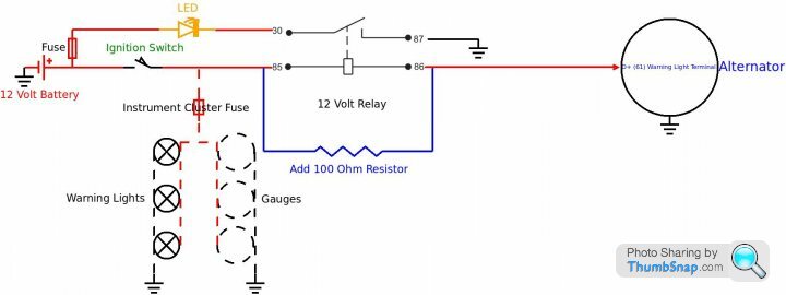
100 Ohm resistor will generate heat until alternator is charging or when a field diode fails to short circuit, best fitted away from anything, bracket on bulkhead or similar for resistor would be good
Edited by Polly Grigora on Thursday 8th December 17:54
Happy to possibly have been of some help, the following diagrams show the situation/difference between a bulb and LED D+ circuit, the big difference being that if a main diode goes short circuit the bulb will illuminate when the ignition is turned off
When using an LED instead of a bulb, an electronic circuit is needed to control the LED correctly so that it will extinguish when the alternator is charging but also illuminate when the ignition is turned off if a main diode has gone short circuit
My method of using a relay as shown above solves the problem if converting a cluster from bulb's to LED's
Have TVR built something into the cluster to control the LED correctly? There could be an electronic circuit built into the cluster and if it fails it will cause all sorts of problems with the alternator LED and cluster behaviour
Here is a field to negative alternator circuit similar to what you have, the alternator doesn't need a bulb for it to cut-in and charge, it does need high revs to get it to cut in as it relies upon the residual magnetism in the rotor to create an output

Below is the very same alternator but the top right main diode has been removed/bridged out to simulate a short circuit main diode

The following shows with red arrows how voltage is now applied from the battery through a short circuit main diode, through a field diode and onwards to the rotor field coil and regulator
This situation causes the alternator to apply a permanent drain of approximately 3 amps across the battery and other circuits could possibly be activated and apply more of a current drain

Finishing off with showing an ignition switch and bulb completing the D+ circuit, with no faulty diodes the alternator will cut-in at much lower revs due to the bulb drawing current through the rotor field coil which in turn creates a bigger magnetic field
Shown below with red arrows is how a short circuit main diode will illuminate a bulb when the ignition is in the off position
An LED without a purpose built control circuit won't illuminate when a main diode goes short circuit as it won't allow current to flow through it in the reverse direction

Edited to add a D+ circuit that uses an LED rather than a bulb, the fact that an LED will draw very little current through the field coil and thus creating a problem with alternator cut-in speed, have added a resistor across the LED to up the current draw
Is the above what TVR have done?
If TVR have included a resistor in the D+ circuit as shown in the below diagram, should a main diode go short circuit it would apply a voltage to ignition controlled circuits when the ignition is off
Am now thinking along the lines that some people are fitting and wiring a diode into the D+ circuit to prevent the cluster etc acting strangely rather than finding the root cause of the problem which would very likely be a short circuit main diode in the alternator or the D+ cable shorting to the battery + cable

When using an LED instead of a bulb, an electronic circuit is needed to control the LED correctly so that it will extinguish when the alternator is charging but also illuminate when the ignition is turned off if a main diode has gone short circuit
My method of using a relay as shown above solves the problem if converting a cluster from bulb's to LED's
Have TVR built something into the cluster to control the LED correctly? There could be an electronic circuit built into the cluster and if it fails it will cause all sorts of problems with the alternator LED and cluster behaviour
Here is a field to negative alternator circuit similar to what you have, the alternator doesn't need a bulb for it to cut-in and charge, it does need high revs to get it to cut in as it relies upon the residual magnetism in the rotor to create an output
Below is the very same alternator but the top right main diode has been removed/bridged out to simulate a short circuit main diode
The following shows with red arrows how voltage is now applied from the battery through a short circuit main diode, through a field diode and onwards to the rotor field coil and regulator
This situation causes the alternator to apply a permanent drain of approximately 3 amps across the battery and other circuits could possibly be activated and apply more of a current drain
Finishing off with showing an ignition switch and bulb completing the D+ circuit, with no faulty diodes the alternator will cut-in at much lower revs due to the bulb drawing current through the rotor field coil which in turn creates a bigger magnetic field
Shown below with red arrows is how a short circuit main diode will illuminate a bulb when the ignition is in the off position
An LED without a purpose built control circuit won't illuminate when a main diode goes short circuit as it won't allow current to flow through it in the reverse direction
Edited to add a D+ circuit that uses an LED rather than a bulb, the fact that an LED will draw very little current through the field coil and thus creating a problem with alternator cut-in speed, have added a resistor across the LED to up the current draw
Is the above what TVR have done?
If TVR have included a resistor in the D+ circuit as shown in the below diagram, should a main diode go short circuit it would apply a voltage to ignition controlled circuits when the ignition is off
Am now thinking along the lines that some people are fitting and wiring a diode into the D+ circuit to prevent the cluster etc acting strangely rather than finding the root cause of the problem which would very likely be a short circuit main diode in the alternator or the D+ cable shorting to the battery + cable
Edited by Polly Grigora on Saturday 10th December 18:21
gruffalo said:
Time to change the regulator, they don't fix themselves.
Every sensor on your engine is designed to work at around 12volts or just over, not 14.5 volt or more hence the poor running.
Sensors work on 5 volt DC, except for O2 sensors which have 12 volts for the heater and output between 0 and 1 volt.Every sensor on your engine is designed to work at around 12volts or just over, not 14.5 volt or more hence the poor running.
Polly Grigora said:
Hello
It won't be a main diode failing
This is correctIt won't be a main diode failing
Polly Grigora said:
Hello
It won't be a main diode failing, if a main diode fails by going short circuit it will then rapidly burn out to then being open circuit
This is a load of bIt won't be a main diode failing, if a main diode fails by going short circuit it will then rapidly burn out to then being open circuit
 ks
ksIt takes more than one main diode to go short circuit before at least one of them burns out
Following can be found at
MattPlaneCrank Launches 100 Amp Fuse Is **** Club
6 x Alternators each having a short circuit diode
100 Amp Main Fuse doesn't blow
Good innit

My apologies for any possible confusion caused
Polly Grigora said:
Information here - https://www.pistonheads.com/gassing/topic.asp?h=0&...
100 Ohm resistor will generate heat until alternator is charging or when a field diode fails to short circuit, best fitted away from anything, bracket on bulkhead or similar for resistor would be good
No way is this correct, the person that posted it must have been on drugs at the time of posting
The below is the truth the whole truth and nothing but the truth
100 Ohm resistor will generate heat until alternator is charging or when a main diode fails to a short circuit state and applies a positive to one of the field diodes, best fitted away from anything, bracket on bulkhead or similar for resistor would be good or better still the resistor could be fitted to the alternator slip-ring end shield at a location inside the rear cover
Please forgive me for my sins, I didn't intentionally post like an idiot, the brain wasn't functioning correctly but is now back in order, all glitches within the skull have been rectified
Polly Grigora said:
Shown below with red arrows is how a short circuit main diode will illuminate a bulb when the ignition is in the off position
Once again something has been missed in the above diagram that was posted earlier to this topicThe red arrows show that a battery positive is directly connected to the (let's call blue phase 3) rotor field coil through the phase 3 field diode which is only one of the three field diodes that make up the diode trio
Red arrows need adding to the diagram to show that the battery positive will also be connected to the phase 1 and phase 2 diodes of the diode trio as it will do so through the stator phase 1 and phase 2 windings that are linked to the phase 3 winding
The above explains how all 3 field diodes (diode trio) will allow current to be drawn through them by the rotor field coil when a positive main diode has gone short circuit
Edited by Polly Grigora on Sunday 11th December 22:41

Gassing Station | Tuscan | Top of Page | What's New | My Stuff