540HP NA 7L V12 3 seater
Discussion


phalanxs said:
One thing I wonder about this build, is why did you choose to use two Honda clutches before the crownwheel, instead of say putting the crownwheel first and using a TR-6060 with its original cluch?
Cheers
Packaging is an important reason, the 2 bellhousings nestle nicely into a space that accomodates the standard corvette input shaft, adding anything to the front of the transaxle kicks the trans back enormously, I do not want to go down the HTT Pléthore path.Cheers
2 clutches also allow me to isolate 1 engine completely, and make the car a little more commuting friendly.
AW111 said:
At a guess, one reason is because a single clutch means the engines are permanently linked, even when cranking / starting - that plus the significantly increased rotational inertia at idle could be an issue.
/me waits for the OP to point out I'm posting b ks.
ks.
True on the permanent linking being something I intend to avoid. Crank harmonics can cause loads many times the rated average crank torque which could cause failures if cranks are bolted directly together or with downstream geartrain components. I have to tap the power off at a right angle so the main reason for doing it my oddball way with 2 DMF's initially is to isolate the gearset from the crank vibrations. A well designed one piece V12 crank resolves these fluctuations within itself, 2 independant motors don't. /me waits for the OP to point out I'm posting b
ks. Rotational inertia at idle is not a factor, in fact it will help with moving off as car should be fairly stall proof given the 2 x heavy flywheels. Future track car development could use aluminium flywheels but my goals are road focused initially so using as many OEM parts as possible.
Progress on the build table has stalled temporarily but should get underway shortly. The donor V6 has been pulled (it sounded great with no pipes, need to upload that video to my you tube page). With drive shafts removed I could fully rev the engine safely with no load, the stock ECU and drive by wire throttle appear quite sluggish. Will compare with the test engine response when running speeduino/direct human controlled throttle plate, I get the feeling the factory ECU is muting the response quite strongly. Time will tell!
Edited by F1natic on Friday 12th January 05:53
The project hiatus is drawing to a close and in preparation for some actual physical progress the full spaceframe was 3D printed at 1/6th scale to help visualise tubing assembly sequence. It was at this point that the potential leg trap was noticed.
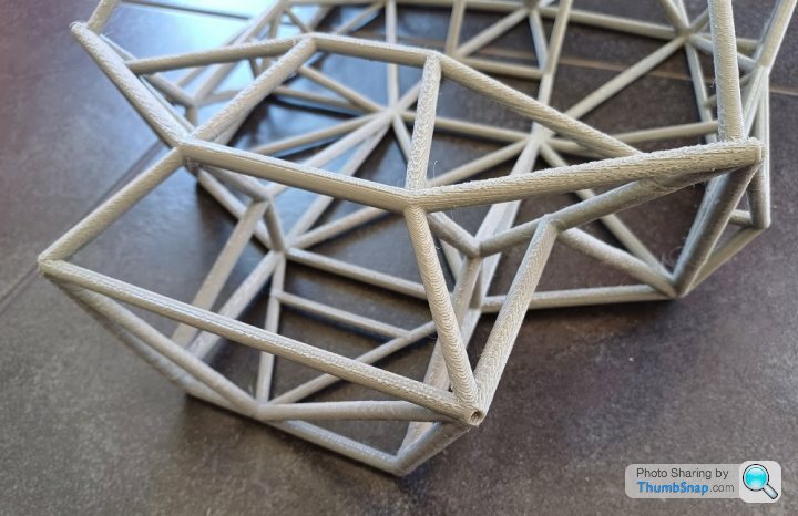
Rotating the structure around in ones hands gives more insight than a 2D screen view and the vulnerability of the footwell upper crosstube to buckling in a side impact was not obvious until it was printed out. The tubing I am using is typically used in sprint car chassis fabrication, the linked video is a superb demonstration of what happens to them in impacts; Ouch.
https://youtu.be/WOsoNGwDTcg?si=O9M8VdTXZlH9sHNi&a...
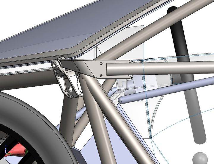
After some node repositioning the structure is now more resistant to sidecrush. Every accident is different and a nose shunt like Flemke's one is probably the most likely due to other road users not seeing the car, however in the case of a rollover/side impact/severe frontal crash the structure has to be well braced to work correctly. The aluminium nose tube structure is intended to absorb crash energy before it reaches the stiffer steel spaceframe. The aluminium radiator mounting frame will aid the crash structure (originally was going to incorporate a bumper bar but it is redundant) and the front suspension tearing off in the typical offside frontal crash should also not damage the drivers legs.
Rotating the structure around in ones hands gives more insight than a 2D screen view and the vulnerability of the footwell upper crosstube to buckling in a side impact was not obvious until it was printed out. The tubing I am using is typically used in sprint car chassis fabrication, the linked video is a superb demonstration of what happens to them in impacts; Ouch.
https://youtu.be/WOsoNGwDTcg?si=O9M8VdTXZlH9sHNi&a...
After some node repositioning the structure is now more resistant to sidecrush. Every accident is different and a nose shunt like Flemke's one is probably the most likely due to other road users not seeing the car, however in the case of a rollover/side impact/severe frontal crash the structure has to be well braced to work correctly. The aluminium nose tube structure is intended to absorb crash energy before it reaches the stiffer steel spaceframe. The aluminium radiator mounting frame will aid the crash structure (originally was going to incorporate a bumper bar but it is redundant) and the front suspension tearing off in the typical offside frontal crash should also not damage the drivers legs.
Had a bit of fun today cowtipping the donor shell using the old EK civic tow vehicle (which is nicknamed "the coackroach" because it refuses to die). Used an engine crane to lift the shell to just under the point of balance. Logs and old wheels make excellent packers.
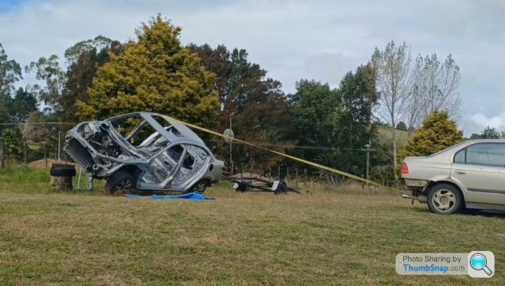
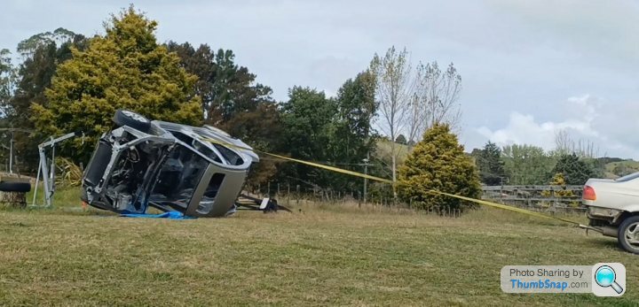
Have stripped out all the under gubbins shown here, which is a much easier task when everything is on it's side as the dirt doesn't fall in your face. The mufflers will most likely be used for the test mule, the evap system and heatshields will be incorporated in the final build and the subframes kept as spare parts for the daily driver.
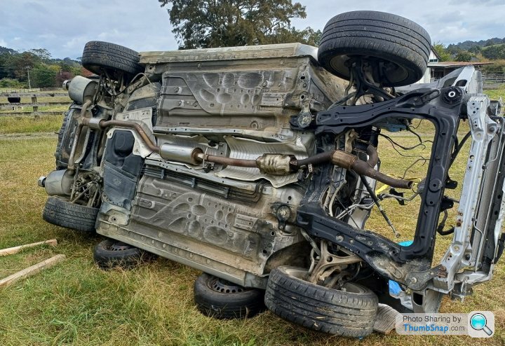
Have stripped out all the under gubbins shown here, which is a much easier task when everything is on it's side as the dirt doesn't fall in your face. The mufflers will most likely be used for the test mule, the evap system and heatshields will be incorporated in the final build and the subframes kept as spare parts for the daily driver.
Edited by F1natic on Sunday 7th April 09:45
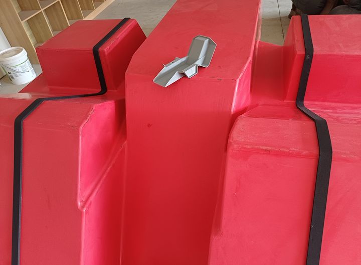
3 years of banging my head against a wall to overcome the issue of a door hinge release mechanism. The solution has to be crash worthy and yet also easy to release when required and upsidedown. 3D printing a prototype out like the image and then off to discuss with the certifier. Don't want to use explosive bolts to release hinge, so finally have a mechanical solution that I am happy with.
eliot said:
Well i wish you the best of luck sir, but i feel the engineering and available budget will see this become another rusty part-finished project on ebay in a couple of years.
May yet be prophetic, but so far the tubing is not rusty....Philosophy ended up being measure 6482 times and cut once. It has taken many years to be sufficiently satisfied with the frame layout. Reviewed final iteration last week with the certifier and no issues to prevent moving onto construction phase. Honestly thought I would have been underway years ago, but see above! Next step is tacking up the passenger rear bulkhead framing so that the engines and trans can be positioned according to CAD layout and real world clearances quadruple checked before proceeding with more frame building. Getting the gearbox in situ then mocking up and testing the gear shift is a critical milestone ahead.
The highly loaded "shock tower" tubes are 4130 cromoly, but the remainder are a mix of 38.1OD 1.6 and 2.6mm wall ERW tube.
Edited by F1natic on Friday 7th June 05:24
PAUL.S. said:
Yes that's the one, and also why I don't do real time build threads anymore, The readers get frustrated when there is no real progress or updates, which is understandable. For mine I take regular pics and plan to do retrospective build thread instead once they are complete
I see the wisdom in your process, and fully respect that. I find a build log is really useful for a number of reasons;- getting input from others, be they experienced builders or not - comments on this thread have been extremely helpful/supportive/encouraging and I appreciate them enormously
- record of goals, ideas and processes - over long periods of time it is easy to loose track/forget the how and why
- it's motivating to post - the lack of physical progress can be highly frustrating for builder and reader alike, but the reality of projects like these is, unless it is your fulltime job, progress is choked by balancing with other aspects of your life. Each small step is still a step in the right direction
- when I started I found very few completed "from scratch" build logs for amateur's to learn from, so hoping at completion this thread will have provided some entertainment, some reliable information and maybe some good "learn from my mistake" moments!
The interior "liner" is formed by 3 separate sections bonded insitu. The center section is made by creating "joggles" at its' edges. The same tool is used to make all three parts, so to create a flush lap joint at the edges the center section has to step up (or down depending on your viewpoint!) using "joggles". In the photo below the tool has a 1/8 scale 3D print of the center section sitting atop. The joggle is formed by a self adhesive backed neoprene foam strip. Gives a nice consistant edges and thickness with which to build up against during the layup. Lots of waxing then PVA spray. Setting up the cabin ergonomics on the build table requires the center section to be made, bulkhead tubing to be in place, a mockup of the powerplant position using the 2 engines and the transaxle held in the correct orientation by a mock up Tbox assembly. The gear shifting mechanism determines the size of the service tube that goes through the fuel tank, so the tank can only be built once the gear shift is tested out in full scale.
Have built a full scale windscreen "former" from 316L castings made from 3D prints. The test mule will be using a polycarbonate screen, so the frame will help with holding the edges to the correct shape during the thermoforming process. It is also extremely useful once covered on the appropriate faces with polypropylene strip (the same thickness as the windscreen) as a plug for creating the matching windscreen recess in the roof moulding. Thus when a glass windscreen is available it should fit too.
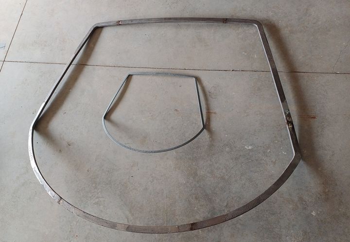
Have built a full scale windscreen "former" from 316L castings made from 3D prints. The test mule will be using a polycarbonate screen, so the frame will help with holding the edges to the correct shape during the thermoforming process. It is also extremely useful once covered on the appropriate faces with polypropylene strip (the same thickness as the windscreen) as a plug for creating the matching windscreen recess in the roof moulding. Thus when a glass windscreen is available it should fit too.
Gassing Station | Readers' Cars | Top of Page | What's New | My Stuff