540HP NA 7L V12 3 seater
Discussion


Yes that's the one, and also why I don't do real time build threads anymore, The readers get frustrated when there is no real progress or updates, which is understandable. For mine I take regular pics and plan to do retrospective build thread instead once they are complete
I stopped posting on fchat some time back now.
I stopped posting on fchat some time back now.
PAUL.S. said:
Yes that's the one, and also why I don't do real time build threads anymore, The readers get frustrated when there is no real progress or updates, which is understandable. For mine I take regular pics and plan to do retrospective build thread instead once they are complete
I see the wisdom in your process, and fully respect that. I find a build log is really useful for a number of reasons;- getting input from others, be they experienced builders or not - comments on this thread have been extremely helpful/supportive/encouraging and I appreciate them enormously
- record of goals, ideas and processes - over long periods of time it is easy to loose track/forget the how and why
- it's motivating to post - the lack of physical progress can be highly frustrating for builder and reader alike, but the reality of projects like these is, unless it is your fulltime job, progress is choked by balancing with other aspects of your life. Each small step is still a step in the right direction
- when I started I found very few completed "from scratch" build logs for amateur's to learn from, so hoping at completion this thread will have provided some entertainment, some reliable information and maybe some good "learn from my mistake" moments!
It was this very thread and your journey thus far that got me even thinking about building a 3 seat F1 LM recreation, initially it was going to be based around a V10 BMW engine and then I started looking for suitable donor chassis. I soon realised it was going to be quite a slog to replicate the body to a level I would be happy with, and the V10 engine itself is fraught with known issues, I already had a decent F136 Maserati/Ferrari engine here, so that became the lump I would use instead, probably turbocharged, then I found a Lotus Evora bare chassis and I was off and running.
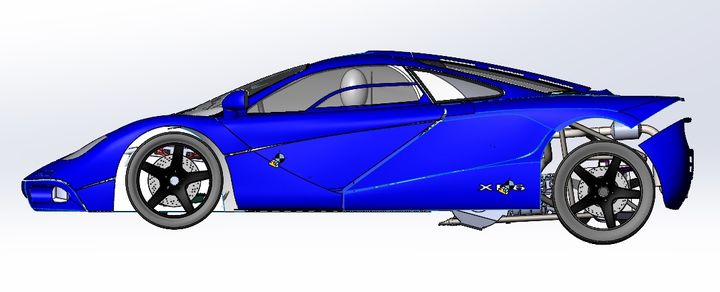
I already have the long term F40 LM project on the go as Dom mentioned, and as I started to work out how to get the correct dimensions for the F1 using the Lotus I realised I would have to compromise quite a few things so decided the alternative path of a bespoke look instead, then I saw pics of the Mazda Furai and that became the inspiration for the design ideas now, that way I do not have to stress over getting all the specific details of the F1 LM right for my build. It was the 3 seat layout that I really wanted, and now with the T50 out there, as well as the Mclaren Speedtail and the Glickenhaus there are plenty of design elements I can utilise.
I am amazed no one else has taken up the challenge of a properly engineered F1 recreation in the last 30 years, the only ones I have seen are squint at 30 foot and don't even dare look whats under the skin lookalikes, your car is going to be amazing when finished, although I shy away from live build threads of my own now, I love reading those of others so please keep up the great work.
My Sunday evening is spent updating You Tube around 7pm ready for the Retro Power weekly vid to drop.
Anyway I will stop diverting this thread now and allow it to get back on track, but happy to answer questions by PM on my own builds.
Edited by PAUL.S. on Saturday 8th June 13:35

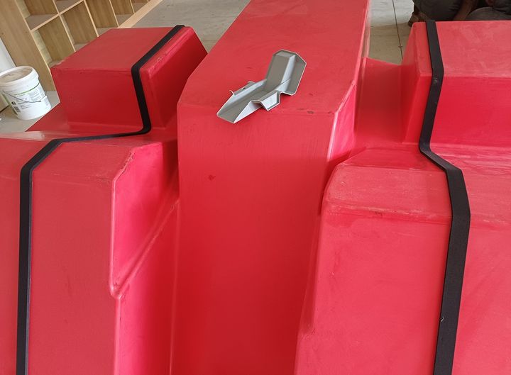
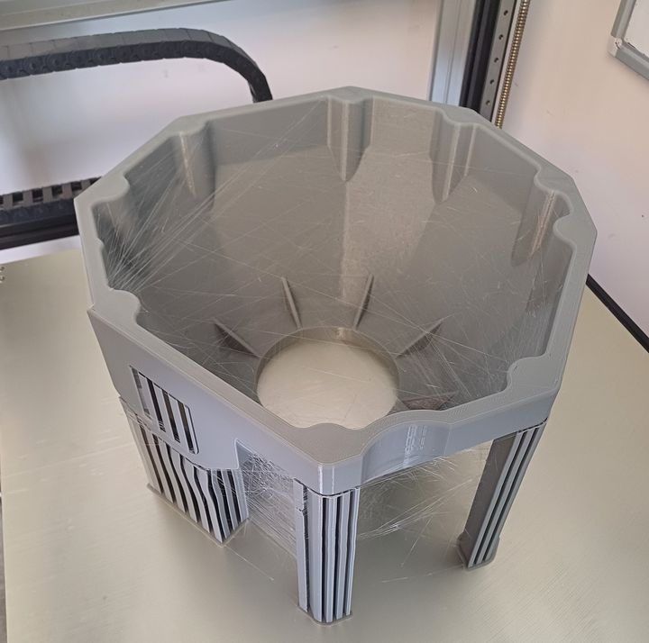
The interior "liner" is formed by 3 separate sections bonded insitu. The center section is made by creating "joggles" at its' edges. The same tool is used to make all three parts, so to create a flush lap joint at the edges the center section has to step up (or down depending on your viewpoint!) using "joggles". In the photo below the tool has a 1/8 scale 3D print of the center section sitting atop. The joggle is formed by a self adhesive backed neoprene foam strip. Gives a nice consistant edges and thickness with which to build up against during the layup. Lots of waxing then PVA spray. Setting up the cabin ergonomics on the build table requires the center section to be made, bulkhead tubing to be in place, a mockup of the powerplant position using the 2 engines and the transaxle held in the correct orientation by a mock up Tbox assembly. The gear shifting mechanism determines the size of the service tube that goes through the fuel tank, so the tank can only be built once the gear shift is tested out in full scale.
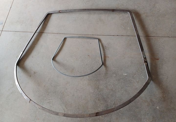
Have built a full scale windscreen "former" from 316L castings made from 3D prints. The test mule will be using a polycarbonate screen, so the frame will help with holding the edges to the correct shape during the thermoforming process. It is also extremely useful once covered on the appropriate faces with polypropylene strip (the same thickness as the windscreen) as a plug for creating the matching windscreen recess in the roof moulding. Thus when a glass windscreen is available it should fit too.
Have built a full scale windscreen "former" from 316L castings made from 3D prints. The test mule will be using a polycarbonate screen, so the frame will help with holding the edges to the correct shape during the thermoforming process. It is also extremely useful once covered on the appropriate faces with polypropylene strip (the same thickness as the windscreen) as a plug for creating the matching windscreen recess in the roof moulding. Thus when a glass windscreen is available it should fit too.
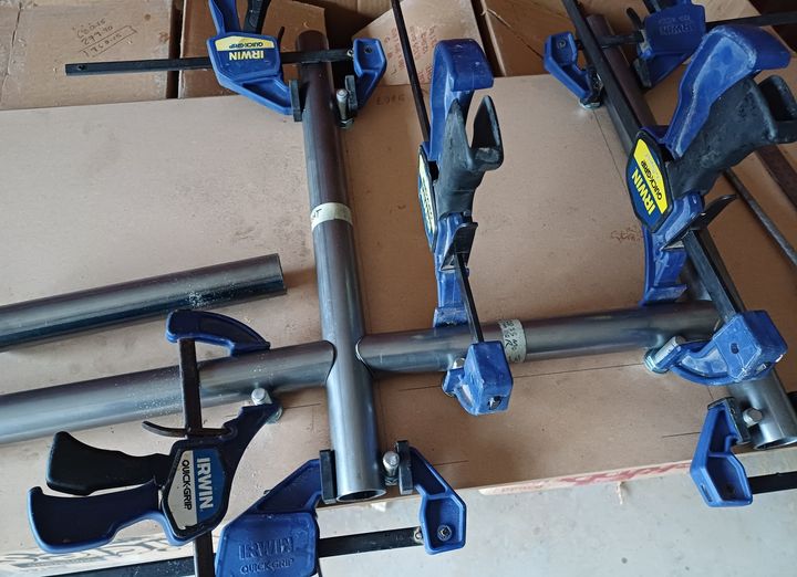
Transitioning from the CAD world to the real world slowly, the learning curve is at level zero but plenty of tubing fishmouth profile dressing experience to come. To assist layout of the roll hoop and rear bulkhead on the build table have built a very portable MDF alignment jig to help with quick positioning during fitup tests, which are done away from the build table initially. The same jig board is used for the side framework and given the studs protrude all the way through and are thus "symmetrical" the jig can be used for both sides of the car. The base edge of the board rests on the build table, so everything can be held in place with clamps before tacking up.
Edited by F1natic on Sunday 14th July 05:36
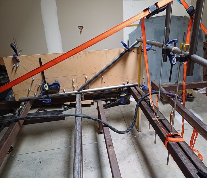
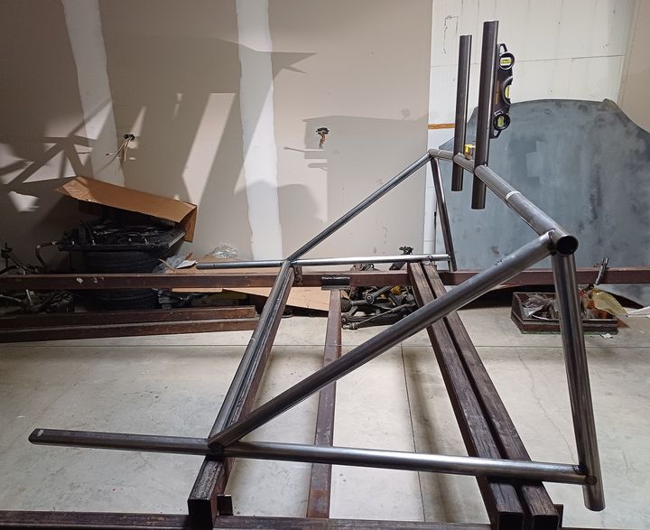
Getting some height on the build table at long last. Building a basic outline frame to be infilled with more tubes after checking the position of the engines and gearchange. The positioning panels are working as intended.
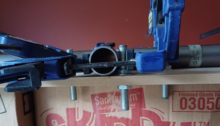
Once the first side was tacked into place the positioning panel was flipped over to the other side. The weight of the center roll hoop section is bourne by the threaded rod tube positioners. The build table cross bars are welded into position on the long side runners, the main crosstube under the drivers butt carries the Datum tube that all other measurements will be taken from. Once the tubing is tacked into position the tabs that hold the cross bars in place are easily broken off and the cross bar reposition for the next build section - the datum tube crossbar will be permanent. Constantly double checking between CAD world and real world to ensure accuracy.
Primary engine bellhousing has the starter motor mount incorporated as the J35 engine has the starter mounted to the transmission. Should be cast in a few weeks time.
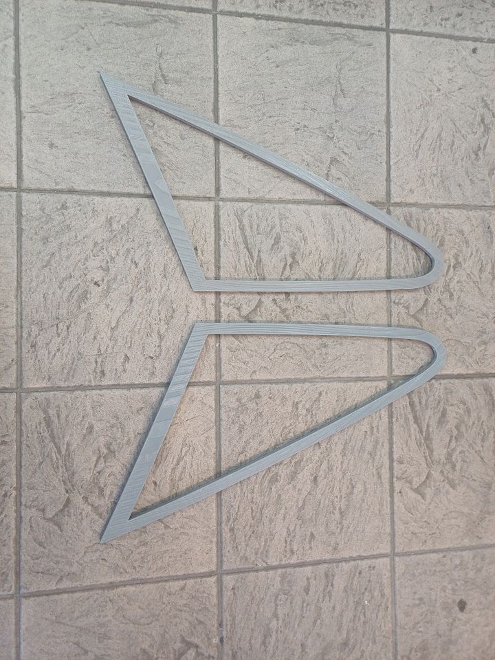
The front windscreen peripheral frame came out really well so have done the same with the rear quarter windows.
Once the first side was tacked into place the positioning panel was flipped over to the other side. The weight of the center roll hoop section is bourne by the threaded rod tube positioners. The build table cross bars are welded into position on the long side runners, the main crosstube under the drivers butt carries the Datum tube that all other measurements will be taken from. Once the tubing is tacked into position the tabs that hold the cross bars in place are easily broken off and the cross bar reposition for the next build section - the datum tube crossbar will be permanent. Constantly double checking between CAD world and real world to ensure accuracy.
Primary engine bellhousing has the starter motor mount incorporated as the J35 engine has the starter mounted to the transmission. Should be cast in a few weeks time.
The front windscreen peripheral frame came out really well so have done the same with the rear quarter windows.
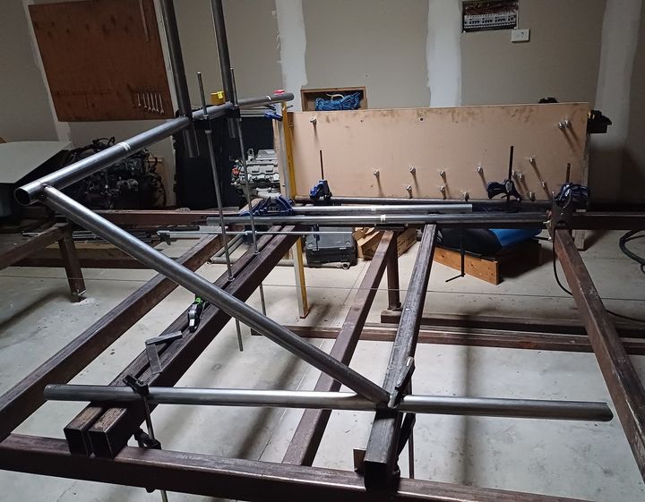
At the point currently where my CAD skills have written a cheque that my FAB skills can't easily cash. Frustratingly slow but overall still progressing. The frame is within a few mm of the CAD dimensions so happy with results, just need to pick up the pace. Now that the foundation tubes are set building out from this point is just more of the same - and the improving weather and daylight hours will help enormously.
Just dropped a shut line question on the aston thread below but thought I would repeat it here as it is a task I need to understand better in the near future;
https://www.pistonheads.com/gassing/topic.asp?h=0&...
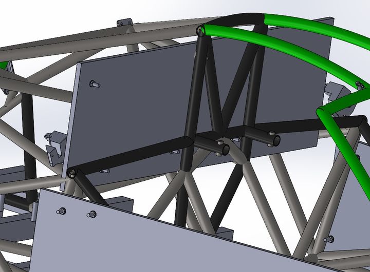
When moulding a door and it's aperture is it better to progress the door through to final part before starting on the door aperture plug? Interested in how one should approach the door panel gapping and fitment, any pearls of wisdom on achieving fine shut lines gratefully received. The image above is the inspiration.
Edited by F1natic on Tuesday 1st October 00:32
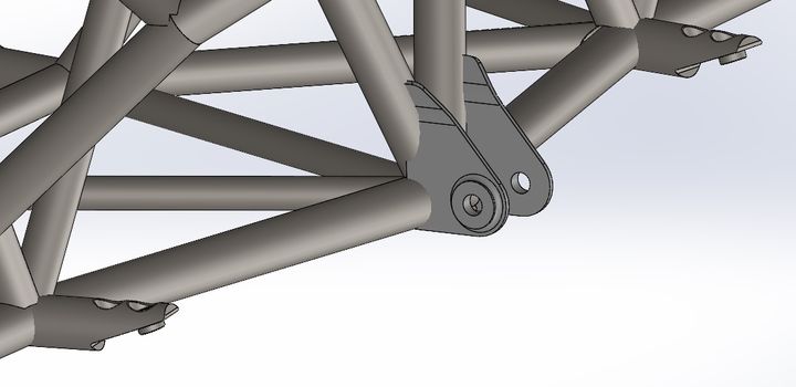
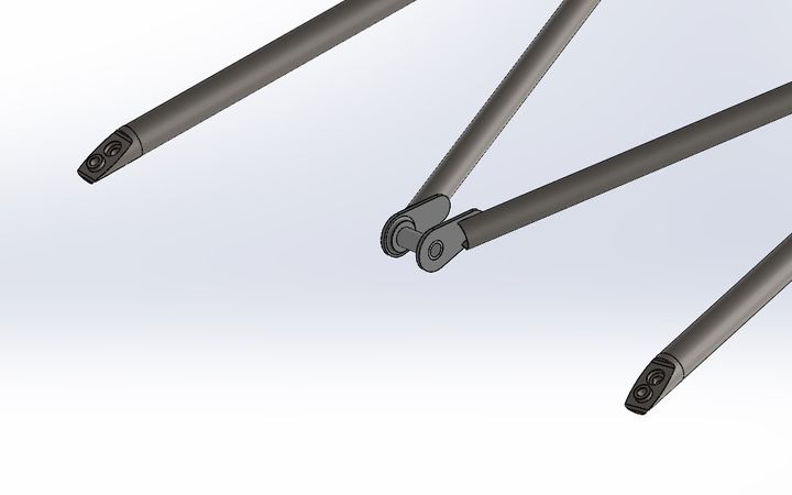
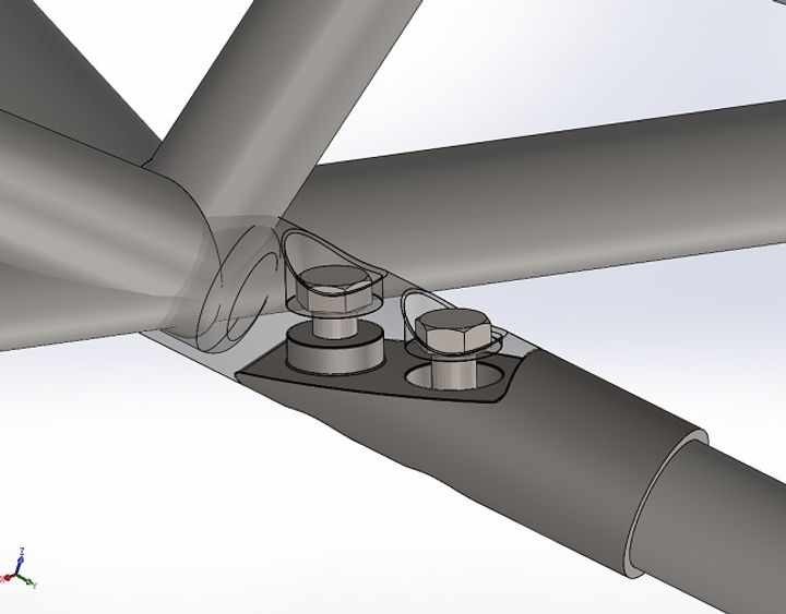
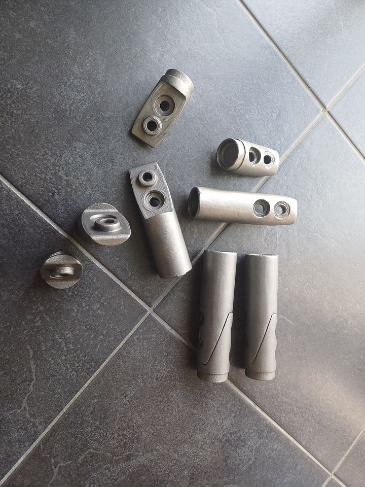
Given the number of times the gearbox and engines are expected to be removed and reinstalled a critical piece of the frame construction are the tubing joints designed a few years ago, which now exist and are ready to be welded in. The race engine pack can also be bolted instead of the OEM units once funds allow.
3D prints cast in BS3100A4, normalized and shotblasted. They still need a quick spot face before final use but chuffed with the results.
Dropping the rear subframe 100 mm allows easy separation from the body.
Normalizing at 960 C
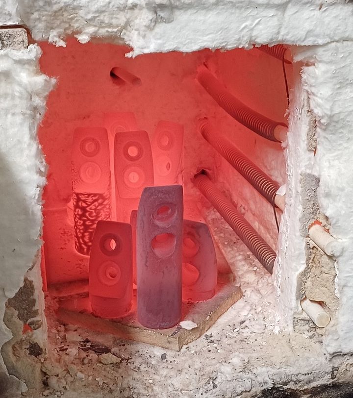
Cooled in still air
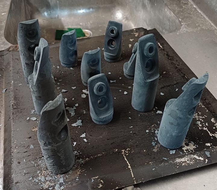
Final parts
3D prints cast in BS3100A4, normalized and shotblasted. They still need a quick spot face before final use but chuffed with the results.
Dropping the rear subframe 100 mm allows easy separation from the body.
Normalizing at 960 C
Cooled in still air
Final parts
Gassing Station | Readers' Cars | Top of Page | What's New | My Stuff