Cars with full fibreglass monocoque?
Discussion
I hate rust so the idea of a fibreglass monocoque appeals to me. Subframes acceptable but no backbone chassis like Lotus or full chassis most kit cars.
To be honest whilst I have a good knowledge about most cars those with fibreglass monocoques don't register very much.
I know of -
Lotus Elite,
Rochdale Olympic
Berkley (although they have riveted in alloy sections like sills - I had a T60)
Mini Marcos
GTM
Midas
Davrian
Quantum
Mini Jem
Pelland
Domino
Mini Minus
Peel Viking (excluding P50 & Trident from this list)
Stewart & Ardern Hawk Sprint
Clan Crusader
Kingfisher Sprint
Anybody add others to the list I've missed ?
Thanks.
Paul H
I think you got most of them , according to the Madaboutkitcars database the following also have composite monococques
Minari
Murtaya
There was also a kit originally made by a couple of boat builders from Ringwood (scuptual engineering) that made a lotus elise styled composite sandwich structure with steel tube front and rear sub frames holding Mk2 Golk running gear. I thing this was then sold onto GTM but was pretty much still born. IIRC it was origninally called the Sculptural Engineering Larini and then the GTM Ballista (think the ballista was converted to space frame chassis). I went to have a look at the original kit and was very impressed, one of my favourite kit cars shame it never made it though.
http://www.premierkitcars.com/larini/
http://www.gtmdrivers.com/forum/post4837.html
Status 365
Status Mini based Matra Rancheroesque estate (can't for the life of me remember it's name)
There was also a trials type 3 wheeler made by Keith Lain of Status which was a monocoque, IIRC only 3 or 4 made.
Paul Hassaueur, (apologies if I've wrongly spelt the surname) of Clan fame made a really pretty Mini based estate car as well.
Many of the above mentioned cars use marine ply in their structures, usually in the sills as it is very strong (and cheap!) when placed on edge as a closing panel.
Compo_Simmonite said:
Shame about the GTM - always assumed fibreglass but after looking at some restoration pics realise they have a steel "punt" that the panels are attached.
Paul h
the steel punt is what kills gtm coupes as well, they rot furiously and are a swine to repair as you have to (normally) take the grp top off to do it - which ends up as a full rebuild.Paul h
I was lucky with mine, its had only ever done 500 miles and was perfect.
the advantage of the punt is that its pretty strong, and the grp is all unstressed so it nice and thin - all the weight is low down so they handle pretty good
guru_1071 said:
the steel punt is what kills gtm coupes as well, they rot furiously and are a swine to repair as you have to (normally) take the grp top off to do it - which ends up as a full rebuild.
I was lucky with mine, its had only ever done 500 miles and was perfect.
the advantage of the punt is that its pretty strong, and the grp is all unstressed so it nice and thin - all the weight is low down so they handle pretty good
Is the steel punt bonded or bolted / riveted to the grp body ?I was lucky with mine, its had only ever done 500 miles and was perfect.
the advantage of the punt is that its pretty strong, and the grp is all unstressed so it nice and thin - all the weight is low down so they handle pretty good
Paul H
CanAm said:
Holy thread revival Batman!
For the sake of historical accuracy I can't leave that unanswered.
No, it was a carbon fibre tub with some GRP body panels.
Unless it was the one that is currently for sale, which was the only one of the six built that had carbon body panels as well (albeit wet lay-up, so not as light and stiff as they could have been)..For the sake of historical accuracy I can't leave that unanswered.
No, it was a carbon fibre tub with some GRP body panels.
In fairness, the panels on the FW400's structural tub used a combination carbon fibre and glass, with a nomex core. The glass was there because pure carbon isn't ideal for crash resistance.
Off Topic - in layman's terms, how are the loads from the metal bits (engine, transmission, suspension etc) carried into and by the GRP?
It all feels a bit snappy offy when I imagine some very localised loads in a structure designed - I believe - to take widespread loads.
Or should I spend an evening fathoming it out among learned papers?
It all feels a bit snappy offy when I imagine some very localised loads in a structure designed - I believe - to take widespread loads.
Or should I spend an evening fathoming it out among learned papers?
DickyC said:
Off Topic - in layman's terms, how are the loads from the metal bits (engine, transmission, suspension etc) carried into and by the GRP?
How layman do you want?The very simplest answer is: by using brackets and local reinforcement of the tub, to spread the loads in to sufficiently wide area, in the right way.
The slightly more techy expansion of that explanation is that brackets and hardpoints should be designed to feed loads in parallel to the skin of the monocoque (ie. pushing/pulling along its surface, rather than perpendicular to it). This often requires that loads are fed in using brackets at corners of the tub, or at a bulkhead, so that a perpendicular or diagonal load vector can be resolved into 'horizontal' and 'vertical' components that run in the direction of the respective skins.
In other words: it needs careful thought and a proper understanding of load paths.
Equus said:
How layman do you want?
The very simplest answer is: by using brackets and local reinforcement of the tub, to spread the loads in to sufficiently wide area, in the right way.
The slightly more techy expansion of that explanation is that brackets and hardpoints should be designed to feed loads in parallel to the skin of the monocoque (ie. pushing/pulling along its surface, rather than perpendicular to it). This often requires that loads are fed in using brackets at corners of the tub, or at a bulkhead, so that a perpendicular or diagonal load vector can be resolved into 'horizontal' and 'vertical' components that run in the direction of the respective skins.
In other words: it needs careful thought and a proper understanding of load paths.
Thanks for that! That's marvellous. Metal bits bonded into the grp structure to support components and guide the load spreading into areas designed to expect them. Is that it?The very simplest answer is: by using brackets and local reinforcement of the tub, to spread the loads in to sufficiently wide area, in the right way.
The slightly more techy expansion of that explanation is that brackets and hardpoints should be designed to feed loads in parallel to the skin of the monocoque (ie. pushing/pulling along its surface, rather than perpendicular to it). This often requires that loads are fed in using brackets at corners of the tub, or at a bulkhead, so that a perpendicular or diagonal load vector can be resolved into 'horizontal' and 'vertical' components that run in the direction of the respective skins.
In other words: it needs careful thought and a proper understanding of load paths.
So when they say of the original Elite that the only metal was the windscreen frame, is that not strictly true?
My dad was a structures man and I had decades of opportunity ask him and just didn't.
DickyC said:
Metal bits bonded into the grp structure to support components and guide the load spreading into areas designed to expect them. Is that it?
Yes, effectively. Usually either 'hardpoints' in the form of metal embedded in the composite layup, or 'bobbins' bonded through it.DickyC said:
So when they say of the original Elite that the only metal was the windscreen frame, is that not strictly true?
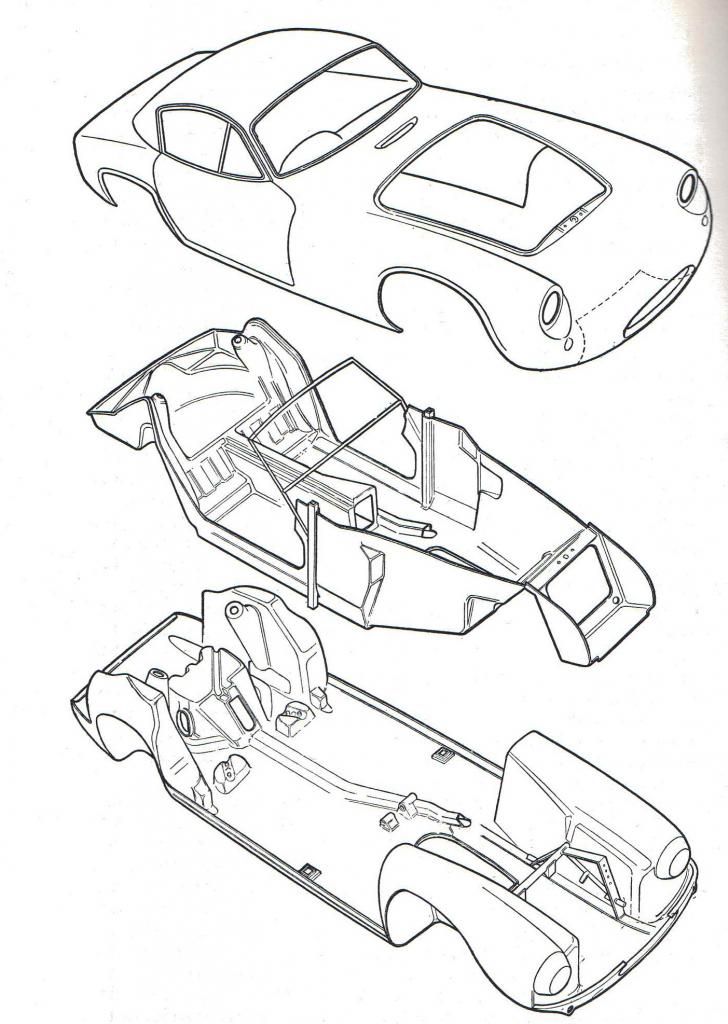
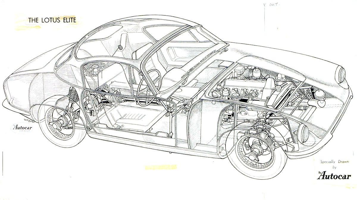
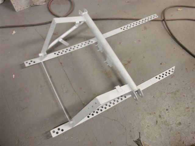
No, it's not true at all. The Lotus Elite (Type 14) used a steel subframe - which was actually a particularly elegant and minimalist piece of design in its own right - to transfer and spread the front suspension and engine loads into the monocoque. This series of images hopefully illustrates:Overall images of the monocoque structure:


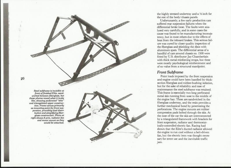
The front subframe. The 'skis' were bonded to the fiberglass undertray... the holes in them were to increase the level of bonding:

You can probably just make out the bottom wishbones on the lower image on this one. The engine was carried on the rubber bobbins you can see immediately to the rear of the wishbone pickup. The bracket above the lower rear wishbone pickup carried the rear link in the upper wishbone, and the forward link was formed by the anti-roll bar, which mounted to the flat 'vertical' strips of steel at the front of the subframe. The subframe also helped carry the radiator and electric fan... all on this tiny, lightweight structure - the Chapman ethos at its best!:

The rear suspension and differential were actually mounted directly to the fibreglass using bolts isolated by rubber bushings, but the thickness of the fibreglass was locally increased to as much as 1/2" in places, and even then the diff had a habit of tearing itself loose (this on a 1216cc engine that produced a mere 95bhp and barely enough torque to pull the skin off a rice pudding), so that's not a solution that many people choose to adopt these days.
Gassing Station | Kit Cars | Top of Page | What's New | My Stuff


