Help with led dash warning lights... cel in particular
Discussion
Hej everyone,
So I have made up a custom dash in my car using a lenovo m8 tablet that runs maxxdash, the app that works with the ecu in the car (maxxecu race). As this is now my only dash, I wanted to wire in some leds for indicators, dipped, main, handbrake etc so it's road legal.
All good so far...
The problem is the cel led, I wired the led + to a 12v ign source and the led - to the cel wire. Everything works fine, ign on, cel light comes on, start car, light goes out.
But that's the problem, the led doesn't go out, not completely, it remains very dimly lit and I want it to go totally out.
So I read this thread here:
https://ls1tech.com/forums/conversions-swaps/16161...
And the guy there says with authority to wire a 7805 between 12v ign and led, but how will that work (it doesn't, I tried)?
Can anyone tell me how to accomplished what I want with the led?
QJumper said:
I did spot that on my travels! So wiring a resistor across the ign + and cel wire might work? Just need to know resistance needed.Polly Grigora said:
Have 5 minutes ago drawn a circuit on paper that works, requires 2 relays, do you want the circuit?
Need some time to draw a tidy circuit
That would be awesome thankyou. My electronics knowledge is lacking I've realised. I have a load of 0.25w resistors and 1w resistors I can use 🙂Need some time to draw a tidy circuit
Polly Grigora said:
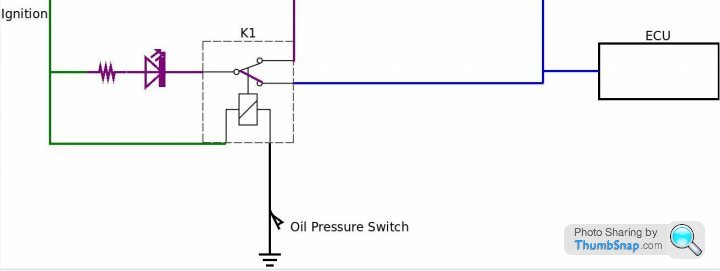
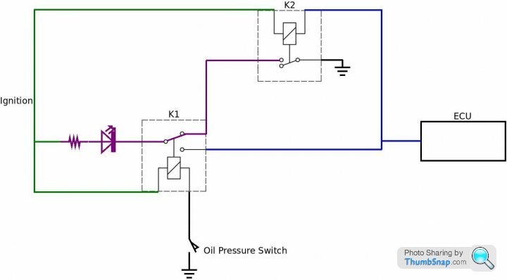
Sorry Polly, can you explain that to me in idiot terms? Does it make any difference if it's the check engine light, not oil pressure? The oil pressure led is fine as it only gets a solid earth or no earth, but the cel gets either earth or 0.7v so still seems to get an earth allowing it to illuminate. The purple coloured LED in the diagram is the CEL
Blue to ECU is CEL cable
Operation 1 - With ignition on, engine not running, oil pressure switch on - Relay K1 is energised/activated, contacts are closed, this connects the LED to the CEL cable and the LED is fully illuminated
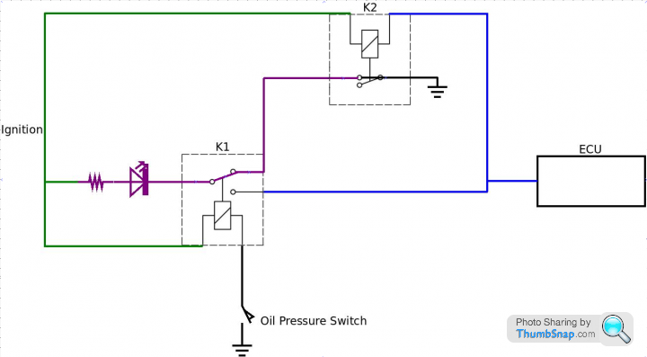
Operation 2 - Engine now running, oil pressure switch off, K1 isn't energised/activated (shown not energised in the diagram), LED is now connected through K1 normally closed contact to a K2 contact
With engine running K2 has 0.7 volts across its coil measured from between its ignition supply and its CEL cable
0.7 volts is too low to energise/activate K2, the LED is not illuminated
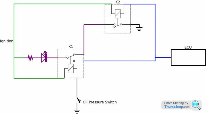
Should a fault occur there will be approximately 12 volts applied to K2 coil, K2 is activated, contacts are closed, this connects a negative (shown with an earth symbol) to the LED and the LED is fully illuminated
Edited by Polly Grigora on Saturday 24th September 12:55
So are you saying that a resistor across the cel and ign will do a similar job? But it will ofcourse dim the cel when lit.
Sorry if it's a dumb question but what happens with the relay solution if the oil pressure triggers, that will also trigger the cel right?
Do you know what relay I need? I live here in sweden and the auto store has some slim pickings!
Sorry if it's a dumb question but what happens with the relay solution if the oil pressure triggers, that will also trigger the cel right?
Do you know what relay I need? I live here in sweden and the auto store has some slim pickings!
nightSpirit said:
Sorry if it's a dumb question but what happens with the relay solution if the oil pressure triggers, that will also trigger the cel right?
The above tells us that the CEL bulb has approximately 12 volts connected across it when the ignition is turned on and it is this 12 volts that informs the driver that the bulb and its circuit is working
Agreed?
Moving on, let's ignore operation 2 for a moment and concentrate on operation 1

Looking at the above diagram, the cars ignition has been turned on but the engine hasn't been started
I have now drawn in a closed oil pressure switch and an activated Relay K1
The LED is connected between the ignition and the CEL cable
The above is exactly the same as what you have now, the LED lights up fully illuminated when the ignition is turned on
Now for the hack that solves the glowing LED problem - Operation 2
Does your car have an oil warning light operated by an oil pressure switch? I think it does
I have used the oil warning light pressure switch to switch over from operation 1 to operation 2 once the engine is running
Operation 2 uses the oil light pressure switch as the engine run signal
As shown in the below diagram, when the engine is running K1 is switched off and the LED is now connected to one of the contacts at K2 which are open because when there are no registered engine electrical component faults there is only 0.7 of a volt across the K2 relay coil which isn't enough to energise/activate it
The negative side of the LED is not connected to anything

If an engine electrical component fails while the engine is running there will be an increase in voltage across the K2 relay coil from 0.7 volts to approximately battery voltage of 12 volts + and K2 will be energised/activated, its contacts are made and an earth is switched to the negative side of the LED which fully illuminates it and warns of a fault. See below

Edited by Polly Grigora on Sunday 25th September 18:59
Polly Grigora said:
Is there 12 volts measured between the ignition and CEL cable when turning the ignition on?
Are you using an LED with a resistor in series that is for use in a 12 volts circuit?
The problem is that the CEL output from the ECU is being driven through a semiconductor which has a finite voltage drop and doesn't get it to quite the battery voltage. With a normal incandescent bulb this is no problem - the current won't be enough to get the lamp to glow. But LEDs don't have a minumum current requirements to glow and will glow even with a tiny current. The solution is to put electronics in series with the LED which block all current until the voltage exceeds some minimum threshold. Are you using an LED with a resistor in series that is for use in a 12 volts circuit?
GreenV8S said:
The problem is that the CEL output from the ECU is being driven through a semiconductor which has a finite voltage drop and doesn't get it to quite the battery voltage. With a normal incandescent bulb this is no problem - the current won't be enough to get the lamp to glow. But LEDs don't have a minumum current requirements to glow and will glow even with a tiny current
CorrectGassing Station | Home Mechanics | Top of Page | What's New | My Stuff


