Headlight levelling motor wiring
Discussion
Here's one for the diode dudes and transistor sisters.
I'm putting together a set of Hella headlights from an old set plus
a spares set I bought.
The main beam units have electric levelling/range adjustment motors I want to get working but no joy so far.
Each range unit is a plastic box that has a Scalextric type 'drum' motor that drives a worm and cog arrangement that makes a plunger go in and out. The plunger has a ball-shaped end that clips into the main beam unit carrier. The carrier then pivots on two similar ball-end pins that locate it.
What's foxing me is the electrical side. each range unit has three wires, a black, a brown and a brown with a trace. Inside each unit is a little PCB, with three power-in connectors and two connectors to the motor. The board also has a number of little doodads (possibly diodes or resistors) and a chip.
On test, the little motors work in both directions and drive the plunger in and out. making it work to 'fully in' made it jam.
As the above shows, I'm no expert but I think the adjusters have a switching device for in/out and some sort of limit switch for the end of adjustment point. But trying random connections with the adjuster assembled gives me a total black action wise.
This is from trying out two of the adjusters and I've yet to try the third. If anyone has any ideas or is just interested, I can add a pic of the board.
... and here is one, in the hope it might ring a bell.
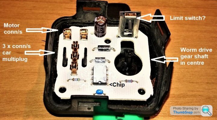
What I've called the 'limit switch' has a peg that can go up and
down. It engages with a ramped brass bracket thing on the
cog that is driven by the motor's worm drive. I'm wondering if this
switch reverses the polarity at each limit.
Everything seems unworn and clean and it's all free to move.
I'm guessing the stripy things on each side of the chip are resistors. As for the three tin cans near the top, I think the vertical black one may be a capacitor? And the little blue pillow at the bottom...no idea.
So...
Nobody? Pity.
What has sprung to mind is this. I've been trying to test run a unit with a live feed and an earth and got no result. Could it be that the thumbwheel on the dash is adjusting a potentiometer? The idea might be that the headlamp motors mimic the position of the thumbwheel and I think this is what the PCB is for.
Hella also offer automatic headlight levellers and these work via a sensor that detects suspesnion movement. The principle should be the same.
I'll have to wait until I have the front bumper off and the headlights out to rig a temporary set of connections as per the originals.
What vehicle have the lights come off? It may be possible to find the wiring diagram or system description online if you know what it came off.
It may be that the light adjuster is position controlled via a simple analogue (i.e. voltage) signal directly from the thumb wheel potentiometer on the adjuster I the dash, or it could be more complex and controlled by an intermediate control module (e.g.” footwell module”) and use a PWM or even serial (can bus) signal to the PCB on the light unit.
It may be that the light adjuster is position controlled via a simple analogue (i.e. voltage) signal directly from the thumb wheel potentiometer on the adjuster I the dash, or it could be more complex and controlled by an intermediate control module (e.g.” footwell module”) and use a PWM or even serial (can bus) signal to the PCB on the light unit.
I suspect that what you have there works like a servo i.e the thumbwheel potentiometer sets the target position and the controller drives the motor to that position. These typically use an oscilator controlled by the potentiometer to drive a pwm signal. Is there any sort of position sensor on the motor/drive mechanism?
Aha, progress! Thank you for your replies.
My car is a 2006 Astra G/Mk.4 and I know that the 'main set of Hella ights came off
one.
My car's original headlights have been replaced (hence no motors) but I expect that what
connects to the thumbwheel will be on there somewhere.
I know my car's too early to have Canbus but there are several ECUs, including one for the electric hood.
Re a position sensor in the motors. Each has a strange, pressed brass thingy that fits onto the plunger cog and seems to engage
with what I called the limit switch.
It looks to me like a good plan would be to connect a new light up to levelling motor plug up front. Changing headlights is a bumper off
task and when I get in there, all should be revealed!
Thanks again.
Enjoy
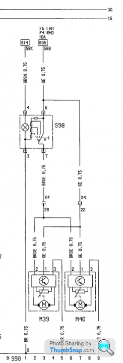
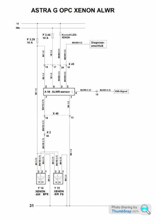
This is for Astra F, shows controlling of motors with variable switched resistance at Brown/Yellow
Note terminal 3 at motor unit is earth
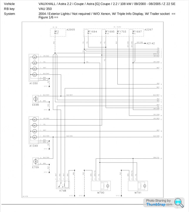
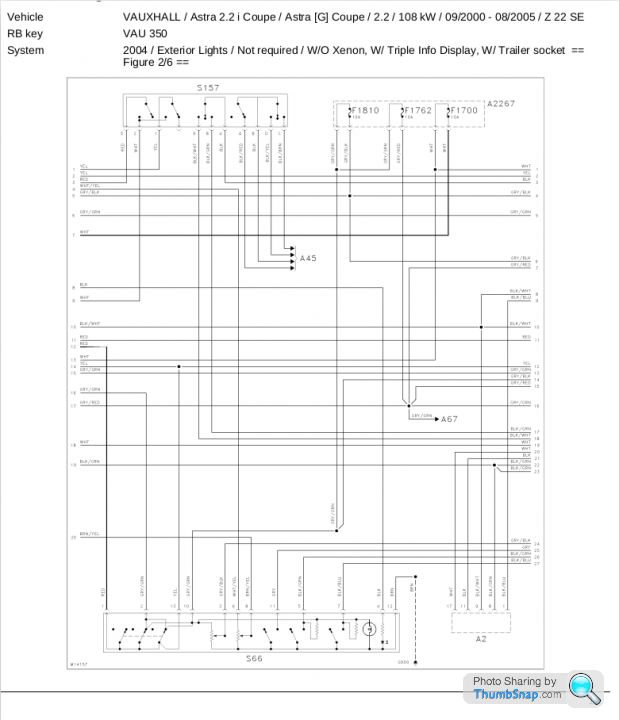
This in 2 parts is for Astra G, shows controlling of motors with variable switched resistance at Brown/Yellow
Switch is numbered S66 in part 2
Note terminal 1 at motor unit is earth
And now for something completely different
This is for Astra F, shows controlling of motors with variable switched resistance at Brown/Yellow
Note terminal 3 at motor unit is earth

This in 2 parts is for Astra G, shows controlling of motors with variable switched resistance at Brown/Yellow
Switch is numbered S66 in part 2
Note terminal 1 at motor unit is earth


And now for something completely different

Excellent, Penelope Stopit, thank you so much. I was seeking such diagrams on Gurgle
last night without result. Very well done for finding and sending them.
Ok, two Qs if I may? Am I right in assuming that the variable switched resistance is the thimbwheel?
Q2 is the part that's really foxing me. here's the mechanism...
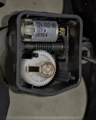
Top to bottom, there are the motor, cog and worm drive and the actuating gear.
The white gear moulding carries a threaded plunger that goes out (away from the camera) and in
to move the main beam light.
What isn't obvious is the brass device that rotates with actuator. It's fixed to the actuator and you can see the 'ramp'
on the left.
Now, take a look at this...
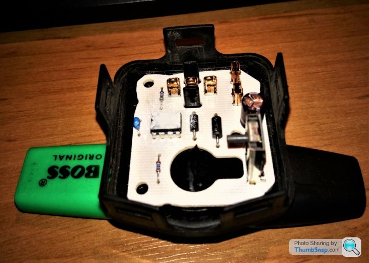
The actuator centres on the black pin in the middle of the 'keyhole'. On the right is what I'm calling
a limit switch and it's prestty clear that the brass device operates it.
Now, imagine flipping this unit with the PCB upside down and clipping it onto the mechanism. I may be wrong but
the brass ramp and switch peg seem to be at an obvious mechanical disadvantage. Sadly, my X-ray vision
is letting me down on this one.
It seems to me to be a highly un-Teutonic arrangement but undoubtedly Helmut knows best.
Looking forward to setting up a jury rig and testing it!
last night without result. Very well done for finding and sending them.
Ok, two Qs if I may? Am I right in assuming that the variable switched resistance is the thimbwheel?
Q2 is the part that's really foxing me. here's the mechanism...

Top to bottom, there are the motor, cog and worm drive and the actuating gear.
The white gear moulding carries a threaded plunger that goes out (away from the camera) and in
to move the main beam light.
What isn't obvious is the brass device that rotates with actuator. It's fixed to the actuator and you can see the 'ramp'
on the left.
Now, take a look at this...

The actuator centres on the black pin in the middle of the 'keyhole'. On the right is what I'm calling
a limit switch and it's prestty clear that the brass device operates it.
Now, imagine flipping this unit with the PCB upside down and clipping it onto the mechanism. I may be wrong but
the brass ramp and switch peg seem to be at an obvious mechanical disadvantage. Sadly, my X-ray vision
is letting me down on this one.
It seems to me to be a highly un-Teutonic arrangement but undoubtedly Helmut knows best.
Looking forward to setting up a jury rig and testing it!
Know what you mean about searching for info, stayed up all night looking for the above
Yes the resistance is variable from thumb-wheel
As for the limit switch, it's the same set-up as many wiper motor park switches, a better job could have been made of it, perhaps a disc and opto-coupler
Manufacturers can't sell parts if the parts used don't break
Yes the resistance is variable from thumb-wheel
As for the limit switch, it's the same set-up as many wiper motor park switches, a better job could have been made of it, perhaps a disc and opto-coupler
Manufacturers can't sell parts if the parts used don't break
Well, thanks again!
The good news is that as you can see from the pics, the hardware is in good shape.
For the limit switch, I'd have used a simple cam moulded into the back of the actuator.
Using something that works at 90 degrees to the obvious plane, as Mr. Hella has,
offends my mechanical sensibilities.
Still, the gear you see has all been out in the muck and bullets at the nose of
the host cars so it could be worse.
davhill said:
What isn't obvious is the brass device that rotates with actuator. It's fixed to the actuator and you can see the 'ramp'
on the left.
My eyes can't make out that thing to the right of the keyhole slot. Can you get a better angle on it?on the left.
That brass arm looks to me as if it is meant to go through the keyhole slot and operate something on the far side of it. Is there a resistive track on the far side of the board around that keyhole opening? Hard to imagine a modern car using something so crude, but I can't imagine what else that brass arm is meant to do.
GreenV8S said:
My eyes can't make out that thing to the right of the keyhole slot. Can you get a better angle on it?
That brass arm looks to me as if it is meant to go through the keyhole slot and operate something on the far side of it. Is there a resistive track on the far side of the board around that keyhole opening? Hard to imagine a modern car using something so crude, but I can't imagine what else that brass arm is meant to do.
Here you are...That brass arm looks to me as if it is meant to go through the keyhole slot and operate something on the far side of it. Is there a resistive track on the far side of the board around that keyhole opening? Hard to imagine a modern car using something so crude, but I can't imagine what else that brass arm is meant to do.
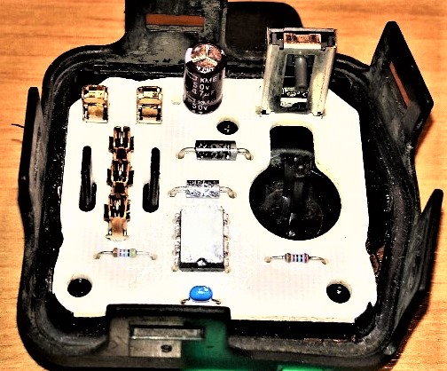
It's a sort of 'skeleton' device. The grey peg moves freely up and down and there are contacts top and
bottom. I think it's a limit switch because by just using + & _ on the motor contacts I proved it's possible
for the motor to jam when the headlight plunger gets to the end of its travel.
There's nothing on the back of the board but for the printed on circuits and the solder holding
the components in place.
Penelope Stopit said:
Looks like the piece of thin steel attached to the white gear moves in and out to operate the limit switch rather than rotating with it
Thanks, Penelope Stopit. It may well do but I doubt I'll ever find out. The gubbins are clipped into a black plastic box so all I can do is test it and if it works, it works. All I know is that replacement units are about £36
a pop so I hope two of the three I have are functional.
davhill said:
Penelope Stopit said:
Looks like the piece of thin steel attached to the white gear moves in and out to operate the limit switch rather than rotating with it
Thanks, Penelope Stopit. It may well do but I doubt I'll ever find out. The gubbins are clipped into a black plastic box so all I can do is test it and if it works, it works. All I know is that replacement units are about £36
a pop so I hope two of the three I have are functional.
NMNeil said:
Without actually looking at one I'm not sure that the metal strip is a limit switch. Most limit switches are a Hall sensor these days. No moving parts to wear out, more reliable, and a lot cheaper than a mechanical switch.
It remains a mystery to me. I can turn the little motor by hand but it's really low geared. This is in the motor casing assembly. Now, take a look at the top cap with the PCB in the picture above. The silver thing in the top RH corner
has a grey peg that can be moved up and down manually. so, if the cog driving the plunger mechanism that moves
the headlamp unit in and out rotates, the brass thingy will brush the peg on the switch and presumably operate it.
It just seems bizarre to have the thing working in the wrong plane, so to speak.
Gassing Station | Home Mechanics | Top of Page | What's New | My Stuff


