Gear ratio maths help
Discussion


Random question but I am sure there is someone on here who will know the answer. Im building a flight sim for s ts and giggles. Currently working on the trim wheel. It will look like this. This isnt mine this is just an example
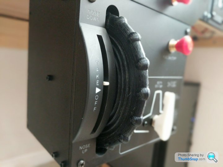
The needle moves up and down based on rotations of the big wheel. My original thought was to use a micro servo and move the needle electronically based on the readings from the wheel rotation potentiometer. But then I thought why not have the needle move mechanically from the wheel rotation using gears. What is the maths that I can calculate what the gear ratios need to be?
If the needle at the top to the neddle at the bottom is x rotations of the wheel, and the needle is y mm in length, what's the formula for the gear ratios?
Thanks in advance
ts and giggles. Currently working on the trim wheel. It will look like this. This isnt mine this is just an exampleThe needle moves up and down based on rotations of the big wheel. My original thought was to use a micro servo and move the needle electronically based on the readings from the wheel rotation potentiometer. But then I thought why not have the needle move mechanically from the wheel rotation using gears. What is the maths that I can calculate what the gear ratios need to be?
If the needle at the top to the neddle at the bottom is x rotations of the wheel, and the needle is y mm in length, what's the formula for the gear ratios?
Thanks in advance
For a flight sim I'd have thought the trim wheel should be giving an input to the sim software (with the software controlling the appropriate friction/resistance for the conditions) and the needle inducator will be moved to the appropriate position by the sim software using a servo. This will make the trim behave appropriately depending on the aircraft type being flown.
48k said:
For a flight sim I'd have thought the trim wheel should be giving an input to the sim software (with the software controlling the appropriate friction/resistance for the conditions) and the needle inducator will be moved to the appropriate position by the sim software using a servo. This will make the trim behave appropriately depending on the aircraft type being flown.
Yeah, that was my first thought and perhaps that is the best approach. I am a little worried about latency, as the trim wheel will have to send info to the sim on the PC via USB, I then have a service receiving events from the sim which is sending data back out via USB to my microprocessors, which would then move the servo. That doesn't sound much, but once finished I'm going to be pumping out a lot of information at a frequency of less than a second to multiple controllers and I think it might get too much.Other option I have is to get rid of the USB and pump the data out over Ethernet.
If you want to do it mechanically, with the needle attached to a driven cog/worm/rack you need to determine how much of a circle the needle needs to move through from end to end. You also need to decide how many turns of the wheel you want to make in order to move the needle through it's full range.
E.g. let's say the needle is going to move a total of 20% or 1/5th of a complete turn. Let's also assume you want to use 10 turns on the wheel to make the full movement. The ratio you need to fulfil this particular example is 50:1 - fifty turns on the wheel would move the needle through a full circle, ergo ten turns would move it through 1/5th of a circle.
E.g. let's say the needle is going to move a total of 20% or 1/5th of a complete turn. Let's also assume you want to use 10 turns on the wheel to make the full movement. The ratio you need to fulfil this particular example is 50:1 - fifty turns on the wheel would move the needle through a full circle, ergo ten turns would move it through 1/5th of a circle.
You can get 6:1 and 10:1 reduction drives quite cheaply from places like Mainline Electronics. They are intended for old style analogue radio tuners. The format is generally 1/4in input and output, with a mounting bracket in the middle.
e.g.
https://www.mainline-group.com/collections/reducti...
https://www.mainline-group.com/collections/small-r...
e.g.
https://www.mainline-group.com/collections/reducti...
https://www.mainline-group.com/collections/small-r...
Scabutz said:
Yeah, that was my first thought and perhaps that is the best approach. I am a little worried about latency, as the trim wheel will have to send info to the sim on the PC via USB, I then have a service receiving events from the sim which is sending data back out via USB to my microprocessors, which would then move the servo. That doesn't sound much, but once finished I'm going to be pumping out a lot of information at a frequency of less than a second to multiple controllers and I think it might get too much.
Other option I have is to get rid of the USB and pump the data out over Ethernet.
Given the potential speed of a USB-serial port, I doubt bandwidth will be a problem (I'm currently pushing one at 460800 baud quite comfortably and that's a hell of a lot of data packets) and, as others have pointed out, it wouldn't be particularly difficult to have more adjustability in the control (you might actually want some latency given that your simulating a lot of gears and linkages) than a fixed mechanical gearing will provide. If you've got a half-decent microcontroller then linearity in the control can go out of the window, both in movement of the servo and response sent back to the PC. I'd also go for a rotary encoder rather than a potentiometer, especially if you want quite a high ratio.Other option I have is to get rid of the USB and pump the data out over Ethernet.
Yup, electronics all the way for this one. And I'm a filthy mechanical too...
Scabutz said:
Random question but I am sure there is someone on here who will know the answer. Im building a flight sim for sts and giggles. Currently working on the trim wheel. It will look like this. This isnt mine this is just an example
The needle moves up and down based on rotations of the big wheel. My original thought was to use a micro servo and move the needle electronically based on the readings from the wheel rotation potentiometer. But then I thought why not have the needle move mechanically from the wheel rotation using gears. What is the maths that I can calculate what the gear ratios need to be?
If the needle at the top to the neddle at the bottom is x rotations of the wheel, and the needle is y mm in length, what's the formula for the gear ratios?
Thanks in advance
It looks like the white plastic indicator travels about 60 degrees (30 up and 30 down from centre), or 1/6th of a rotation.ts and giggles. Currently working on the trim wheel. It will look like this. This isnt mine this is just an exampleThe needle moves up and down based on rotations of the big wheel. My original thought was to use a micro servo and move the needle electronically based on the readings from the wheel rotation potentiometer. But then I thought why not have the needle move mechanically from the wheel rotation using gears. What is the maths that I can calculate what the gear ratios need to be?
If the needle at the top to the neddle at the bottom is x rotations of the wheel, and the needle is y mm in length, what's the formula for the gear ratios?
Thanks in advance
So the indicator moves "1/(6x)" times the speed of the wheel (using your definition of 'x'), or 6x : 1 as a ratio.
y is irrelevant (eg if you made the whole thing 10x larger the gear ratios would stay the same even though y has increased)
Eg if you wanted 4 rotations of the wheel between the up/down extremes, you might have a small 10-tooth cog attached to the wheel driving a 240-tooth cog for the indicator.
Edited by FarmyardPants on Tuesday 7th September 10:13
Just to add, a simple 2-cog arrangement would result in the needle moving in the opposite direction to the wheel. If that's undesirable, you'd need an intermediate cog. It doesn't matter how many teeth the intermediate cog has, if all the cogs mesh at their perimeters.
Edited by FarmyardPants on Tuesday 7th September 10:50

Scabutz said:
48k said:
For a flight sim I'd have thought the trim wheel should be giving an input to the sim software (with the software controlling the appropriate friction/resistance for the conditions) and the needle inducator will be moved to the appropriate position by the sim software using a servo. This will make the trim behave appropriately depending on the aircraft type being flown.
Yeah, that was my first thought and perhaps that is the best approach. I am a little worried about latency, as the trim wheel will have to send info to the sim on the PC via USB, I then have a service receiving events from the sim which is sending data back out via USB to my microprocessors, which would then move the servo. That doesn't sound much, but once finished I'm going to be pumping out a lot of information at a frequency of less than a second to multiple controllers and I think it might get too much.Other option I have is to get rid of the USB and pump the data out over Ethernet.
Another reason for going the electronics route is if you fly something with an autopilot the sim can set the trim position.
There are plenty of off the shelf options if you don't want to mess about with microcontrollers and soldering irons.

Thanks all, the picture above the person is using a servo and actually has shared all their 3d printing plans so I will use those (but not their settings :-))
The CAD side of things is my weakest area and takes a long time so re using what others have done is probably the better way to go
The CAD side of things is my weakest area and takes a long time so re using what others have done is probably the better way to go
Gassing Station | Science! | Top of Page | What's New | My Stuff