Calculating the strength of a length of angle steel. URGENT.
Discussion


Hi, I have made a 2 meter long beam, with a lifting eye and chain at each end to lift a 200kg (overestimated) bench 200mm from the floor.
Before the beam is used I checked with the health and safety at work, who were happy with all aspects (all lifting eyes and chains have a suitable rating etc) except the strength of the beam, for which I have no data.
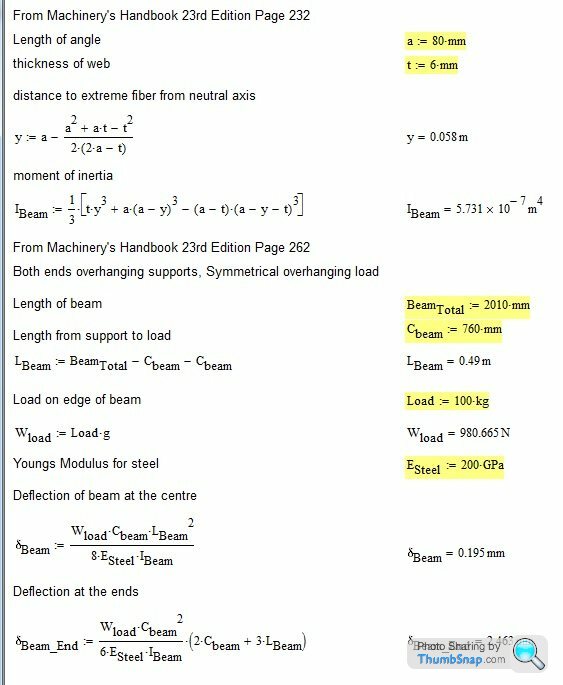
The beam is 80x80x6mm and 2010mm long.
The beam is attached to the forks of a forklift, with each fork being 760mm from the end of the beam.
The beam is mild steel.
Is there any way to calculate the deflection of the beam?
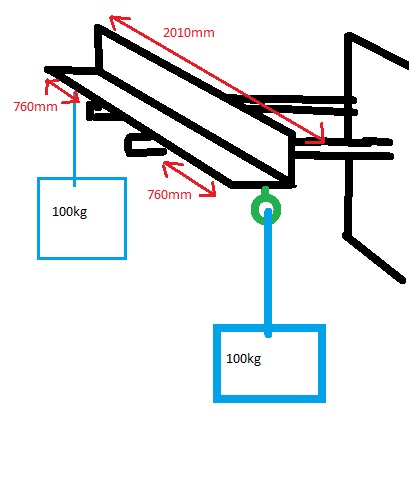
Please assume the weight of the bench is spread evenly on ends of beam.
Please include formulas so that I can re prove the calculations.
Any help appreciated.
Thank you very very much.
Before the beam is used I checked with the health and safety at work, who were happy with all aspects (all lifting eyes and chains have a suitable rating etc) except the strength of the beam, for which I have no data.
The beam is 80x80x6mm and 2010mm long.
The beam is attached to the forks of a forklift, with each fork being 760mm from the end of the beam.
The beam is mild steel.
Is there any way to calculate the deflection of the beam?
Please assume the weight of the bench is spread evenly on ends of beam.
Please include formulas so that I can re prove the calculations.
Any help appreciated.
Thank you very very much.
Edited by Benbay001 on Wednesday 27th February 17:07
Edited by Benbay001 on Wednesday 27th February 17:08
Krikkit said:
Plug your numbers into this: https://www.amesweb.info/StructuralBeamDeflection/...
Thank you, it was very helpful.Luckily, this morning, I was able to get someone from our drawing office to model for finite element analysis, so problem solved.
Thanks again
bucksmanuk said:
I suspect you have a slide rule somewhere and can still use it 
That comment made me think the last film I recall "old fashioned" work books and slide rules were in was Apollo 13 film https://vimeo.com/34664087 here is a clip and for those of you too young to have used such a tool consider this, when the latest space capsules have an issue with power/screens/ computers will the crew have the skill set to manually make calculations manually, because it was those skills "up there" and back on earth that saved them.
Edited by Toaster on Thursday 7th March 15:47
Toaster said:
I suspect you have a slide rule somewhere and can still use it
That comment made me think the last film I recall "old fashioned" work books and slide rules were in was Apollo 13 film https://vimeo.com/34664087 here is a clip and for those of you too young to have used such a tool consider this, when the latest space capsules have an issue with power/screens/ computers will the crew have the skill set to manually make calculations manually, because it was those skills "up there" and back on earth that saved them.
Have a slide rule? … Yes….That comment made me think the last film I recall "old fashioned" work books and slide rules were in was Apollo 13 film https://vimeo.com/34664087 here is a clip and for those of you too young to have used such a tool consider this, when the latest space capsules have an issue with power/screens/ computers will the crew have the skill set to manually make calculations manually, because it was those skills "up there" and back on earth that saved them.
Edited by Toaster on Thursday 7th March 15:47
Know how to use it? …. Just…..
Benbay001 said:
Donbot said:
displacement of 2.1mm. (Inventor).
2.08 from the FEA so well done 
Anyway, I've had a quick look at this and whilst the deflections are heading in the right direction, I don't think they're quite right as they appear (including the MathCAD calc) to be based on pure bending. This is naturally a valid approach but does not appear to consider the use of an non-symetric angle section, which would require either more hand calcs or a more involved FEM.
Based on what's been done, you'd get a bending moment of about 750Nm. With the fibre distance and Ixx already calculated you'd have a stress of about 80MPa, which is well below that of mild steel (approx 350MPa). Your RF = 4.37, which on first glance looks fine but doesn't really tell the whole story.
Looking at your sketch, the load points appear to be at the middle of the horizontal flange. As the shear centre is located roughly at the corner of the angle, then the load will generate torsion. This coupled with the rather long overhangs will result in instability so lateral buckling will be a factor.
I'm assuming the angle section was more readily available (or cheaper) so is fair enough but it would have been preferable to use either an 'I' beam or box section to eliminate this effect.
The deflection should be between 2-3 times what's been calculated. If you consider lateral buckling/instability then the RF = 1.5 so significantly lower than above.
I'm not sure what requirements you have for lifting equipment (I generally work to a factor of 4) but given you say your 100kg loads are an over estimate then your RF may be closer to 2. Naturally the actual margins will be dependent on the quality of material and how your beam has been manufactured.
For this job you're likely to be ok but just bear in mind that if you're thinking of using this again for heavier loads then it's worth another assessment.
Hope this helps.
Donbot said:
The lateral buckling is shown in the FEA, so I assume it is properly accounting for it.
I don't know enough about these things to start an argument though
No worries. I'm not the argumentative type I don't know enough about these things to start an argument though
FE packages differ but my guess is that it may not be, given the correlation between the 2mm deflection from your FEM and the MathCAD calc.
I did a hand calc and also used winbeam, which both gave similar deflections of 2mm. It was only when I modelled the beam using plate elements that I got the larger displacement (~6mm).
It's possible Inventor does both analyses in one go but typically it requires a separate solution to calculate the buckling modes (eigenvalues).
SOL111 said:
It's possible Inventor does both analyses in one go but typically it requires a separate solution to calculate the buckling modes (eigenvalues).
Having a quick read it looks like you are correct that basic FEA won't give accurate answers on asymmetric beam loads.OP should have used box section

Gassing Station | Science! | Top of Page | What's New | My Stuff