Analog Voltage Smoothing Calculations
Discussion


I appreciate this may not be the correct section, but someone may be able to point me in the right direction!
Running a small microcontroller to sample fuel level in a (race) car. Standard tank. Standard fuel level float (simple variable resistance). I run this through a 5v voltage divider, and get a resulting voltage reading. I know what voltage equates to number of litres in the tank, which is great when it is settled and sat still, but that is irrelevant for the reason of this post.
The microcontroller simply processes the voltage, and forwards the reading over to a dash digitally. The problem I have is fluctuation in samples, which is to be expected when a car is accelerating, braking and cornering. I have tried various calculations to 'smooth' this reading, but I am hoping someone can further improve this as the reading is still not of much use.
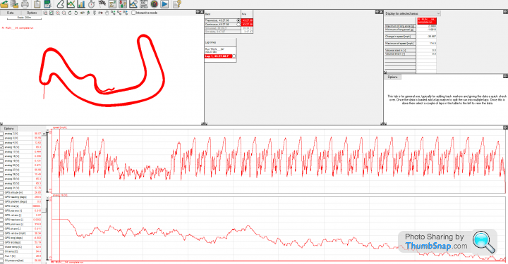
I am currently using a rolling average, whereby the oldest value is removed and latest one added, every second. I am storing 180 samples in this array (3 minutes), then recalculating the average as this happens. I had previously tried two minutes (120 samples), but there was still far too much fluctuation in the resulting average. The below log is showing approximately 45 minutes, the lower trace being fuel level:
The issues I can see with this are, it is still not 'smooth' enough to give a good indication of fuel level. The car is used for endurance racing (2-3 hours), with multiple re-fuels and without having an accurate(ish) level we are currently running blind.
I could increase the samples to four minutes say, but then the delay in change would be higher, and quite an amount of fuel could be consumed in that time dependant on circuit. The car currently uses anywhere between 0.5-0.65L/min at full pace.
Does anyone have any ideas on how I could calculate this more accurately? Maybe take more samples over the same period (0.5s)? Any advice would be appreciated!
Running a small microcontroller to sample fuel level in a (race) car. Standard tank. Standard fuel level float (simple variable resistance). I run this through a 5v voltage divider, and get a resulting voltage reading. I know what voltage equates to number of litres in the tank, which is great when it is settled and sat still, but that is irrelevant for the reason of this post.
The microcontroller simply processes the voltage, and forwards the reading over to a dash digitally. The problem I have is fluctuation in samples, which is to be expected when a car is accelerating, braking and cornering. I have tried various calculations to 'smooth' this reading, but I am hoping someone can further improve this as the reading is still not of much use.
I am currently using a rolling average, whereby the oldest value is removed and latest one added, every second. I am storing 180 samples in this array (3 minutes), then recalculating the average as this happens. I had previously tried two minutes (120 samples), but there was still far too much fluctuation in the resulting average. The below log is showing approximately 45 minutes, the lower trace being fuel level:
The issues I can see with this are, it is still not 'smooth' enough to give a good indication of fuel level. The car is used for endurance racing (2-3 hours), with multiple re-fuels and without having an accurate(ish) level we are currently running blind.
I could increase the samples to four minutes say, but then the delay in change would be higher, and quite an amount of fuel could be consumed in that time dependant on circuit. The car currently uses anywhere between 0.5-0.65L/min at full pace.
Does anyone have any ideas on how I could calculate this more accurately? Maybe take more samples over the same period (0.5s)? Any advice would be appreciated!
Edited by f0xy on Thursday 25th October 16:58
You could place a small value capacitor across the analogue output, and that would damp the fluctuations.
What you really want though, it to feed the analogue output into an integrator.
You can then adjust R/C values to give you the optimum amount of "smoothing".
What you really want though, it to feed the analogue output into an integrator.
You can then adjust R/C values to give you the optimum amount of "smoothing".
Edited by TonyRPH on Thursday 25th October 19:27
https://en.m.wikipedia.org/wiki/Butterworth_filter Maybe?
Would have thought it’s easier and more reliable to measure fuel in and out in practice and calculate your fuel consumption rate, or even better if your logger is up to it you can use the injector pulse time to create a real time fuel consumed figure although presumably it’ll need a fair amount of work to calibrate it.
Either one of these is what has been done in every endurance race I’ve done, I can’t say I’ve relied on a fuel level gauge in a racing car. Doesn’t mean to say it can’t be done or it’s wrong but there must be a reason no one else does it!
The Wookie said:
A filter is unlikely to help.As per my post, an integrator should do the trick.
It will smooth the voltage output (but still maintain the correct analogue voltage levels) it will just slow voltage changes over time.
Hence constant fluctuations will be 'smoothed' out but the guage reading will remain correct.

You need a non linear filter, because the one thing you know, is that the tank doesn't "fill up" as the car races round the track!
Ie, you limit any INCREASE many more times than any decrease, By using a rate limiter you immediately remove significant variation. If you put the raw data into Excel (or matlab if you have access) you can post process against various gains and limits to see which looks to be the best approximation. You also may simply want to use an external estimated consumption (ie from integrated engine power, or injector pulsewidth) and kalman filter between the two to estimate the true fuel load. When the car is dynamic the kalman filter biases towards the estimator, and towards the measured value when things are more stable (say at the end of the straight before you brake) Here, you will want to pull off LAT/LON g to use as your weighting arbitrator
Ie, you limit any INCREASE many more times than any decrease, By using a rate limiter you immediately remove significant variation. If you put the raw data into Excel (or matlab if you have access) you can post process against various gains and limits to see which looks to be the best approximation. You also may simply want to use an external estimated consumption (ie from integrated engine power, or injector pulsewidth) and kalman filter between the two to estimate the true fuel load. When the car is dynamic the kalman filter biases towards the estimator, and towards the measured value when things are more stable (say at the end of the straight before you brake) Here, you will want to pull off LAT/LON g to use as your weighting arbitrator
BTW, looking by eye at your raw data, i would suggest that you are not in fact ever actually measuring fuel level! You are measuring the g force on the sensor (sensor might be longitudinal or lateral, i'd guess longitudinal). ie, it's not the fuel sloshing around that's moving the float, it's the float being flung around itself!
No filter in the world can "average" data that isn't there in the first place!
On your raw chart above, it certainly fails the "eye-crometer" test, as it's difficult to see any significant downwards trend in the data with time, right until the last lap in fact, that suddenly shows a trend.
To avoid G force actuating the float, switch to a well baffled capacitive type gauge, which at least provides an independent capacitance that can be time averaged
[b]
ETA, that's ^^^ probably all b*ll*cks because i've just realised your upper chart may actually be speed and not raw fuel level!!!!!
[/b]
TonyRPH said:
You could place a small value capacitor across the analogue output, and that would damp the fluctuations.
What you really want though, it to feed the analogue output into an integrator.
You can then adjust R/C values to give you the optimum amount of "smoothing".
What you really want though, it to feed the analogue output into an integrator.
You can then adjust R/C values to give you the optimum amount of "smoothing".
Edited by TonyRPH on Thursday 25th October 19:27
The Wookie said:
https://en.m.wikipedia.org/wiki/Butterworth_filter Maybe?
Would have thought it’s easier and more reliable to measure fuel in and out in practice and calculate your fuel consumption rate, or even better if your logger is up to it you can use the injector pulse time to create a real time fuel consumed figure although presumably it’ll need a fair amount of work to calibrate it.
Either one of these is what has been done in every endurance race I’ve done, I can’t say I’ve relied on a fuel level gauge in a racing car. Doesn’t mean to say it can’t be done or it’s wrong but there must be a reason no one else does it!
Thank you for the replies everyone.Would have thought it’s easier and more reliable to measure fuel in and out in practice and calculate your fuel consumption rate, or even better if your logger is up to it you can use the injector pulse time to create a real time fuel consumed figure although presumably it’ll need a fair amount of work to calibrate it.
Either one of these is what has been done in every endurance race I’ve done, I can’t say I’ve relied on a fuel level gauge in a racing car. Doesn’t mean to say it can’t be done or it’s wrong but there must be a reason no one else does it!
In an ideal world I could process the injector PW v/s fuel pressure and injector size, but like you say it would take a fair amount of setting up and time. Not to mention the fact this particular car isn't running anything special ECU wise (Hondata KPro), and there is no access to a serial data stream from it 'live'. If that was the case I would have already have attempted it, as I can program quicker than design electronics

Anything we are logging has been added and calibrated manually, along with the fuel level sensor. I'm far from knowledgeable in electronics, and have just thrown this together with trial and error over the course of the year, currently at the stage as per the first post. This is literally club level motorsport, no huge budgets and most things have been designed/implemented ourselves.
Tony, thank you for the information, I am looking into that now!
Max_Torque said:
You need a non linear filter, because the one thing you know, is that the tank doesn't "fill up" as the car races round the track!
Ie, you limit any INCREASE many more times than any decrease, By using a rate limiter you immediately remove significant variation. If you put the raw data into Excel (or matlab if you have access) you can post process against various gains and limits to see which looks to be the best approximation. You also may simply want to use an external estimated consumption (ie from integrated engine power, or injector pulsewidth) and kalman filter between the two to estimate the true fuel load. When the car is dynamic the kalman filter biases towards the estimator, and towards the measured value when things are more stable (say at the end of the straight before you brake) Here, you will want to pull off LAT/LON g to use as your weighting arbitrator
Ie, you limit any INCREASE many more times than any decrease, By using a rate limiter you immediately remove significant variation. If you put the raw data into Excel (or matlab if you have access) you can post process against various gains and limits to see which looks to be the best approximation. You also may simply want to use an external estimated consumption (ie from integrated engine power, or injector pulsewidth) and kalman filter between the two to estimate the true fuel load. When the car is dynamic the kalman filter biases towards the estimator, and towards the measured value when things are more stable (say at the end of the straight before you brake) Here, you will want to pull off LAT/LON g to use as your weighting arbitrator
Max_Torque said:
BTW, looking by eye at your raw data, i would suggest that you are not in fact ever actually measuring fuel level! You are measuring the g force on the sensor (sensor might be longitudinal or lateral, i'd guess longitudinal). ie, it's not the fuel sloshing around that's moving the float, it's the float being flung around itself!
No filter in the world can "average" data that isn't there in the first place!
On your raw chart above, it certainly fails the "eye-crometer" test, as it's difficult to see any significant downwards trend in the data with time, right until the last lap in fact, that suddenly shows a trend.
To avoid G force actuating the float, switch to a well baffled capacitive type gauge, which at least provides an independent capacitance that can be time averaged
[b]
ETA, that's ^^^ probably all b*ll*cks because i've just realised your upper chart may actually be speed and not raw fuel level!!!!!
[/b]
Yes, the top trace is speed, the bottom trace is the 'averaged' reading from the micro controller No filter in the world can "average" data that isn't there in the first place!
On your raw chart above, it certainly fails the "eye-crometer" test, as it's difficult to see any significant downwards trend in the data with time, right until the last lap in fact, that suddenly shows a trend.
To avoid G force actuating the float, switch to a well baffled capacitive type gauge, which at least provides an independent capacitance that can be time averaged
[b]
ETA, that's ^^^ probably all b*ll*cks because i've just realised your upper chart may actually be speed and not raw fuel level!!!!!
[/b]
Sorry, I should have stated that in the original post.Good suggestions with referencing it against known fuel consumption, as above I have mentioned 'easy' access to the injector PW values is not there and it would be great if it was... but hey ho. We know the car uses approximately 35 litres an hour, in the dry, at a decent pace. Obviously this changes at different circuits, and weather conditions etc.
You could well be correct regarding the float, its actually forward facing, so could technically be affected by braking and acceleration, not sure how much mind. I can 'hear' when the tank is running very low, as the lift pump in the tank starts to draw air, and the tone changes - not a major issue as the swirl pot still has sufficient fuel to run the car until the fuel comes back across the tank. I would rather know before this happens though!
I should also mention, one of the other things I tried 'in software' was, before calculating the average of the array, sorting it low>high, removing the top 30 samples, and bottom 30 samples, then averaging the remaining 120, but it gave some very strange results and the reading seemed to remain far too constant
TonyRPH said:
A filter is unlikely to help.
As per my post, an integrator should do the trick.
It will smooth the voltage output (but still maintain the correct analogue voltage levels) it will just slow voltage changes over time.
Hence constant fluctuations will be 'smoothed' out but the guage reading will remain correct.
Sure but same difference to using a rolling average isn’t it? I was thinking more you’d apply that filter to what goes into the rolling average calc.As per my post, an integrator should do the trick.
It will smooth the voltage output (but still maintain the correct analogue voltage levels) it will just slow voltage changes over time.
Hence constant fluctuations will be 'smoothed' out but the guage reading will remain correct.
I think Max Torque has it about right though with a non linear job
The other question is whether you could get it to ignore the input during longitudinal and latacc events above a certain level to avoid the peaks in error
IANACSE

The data you show:
Are the x axes for the two graphs coincident?
There looks to be a significant delay between the smoothed output and the speed trace.
Do you have a raw data trace?
As another poster has observed, however, the raw data might well be so poor that you can't get a sensible answer - GIGO.
You spend a far higher proportion of the lap accelerating than you do braking or constant speed (of course).
You are also assuming that the relationship of fuel level w.r.t. acceleration is linear. It may well not be.
I agree making an mpg type calculator based on injector pulse rate& duration is likely to give a better answer. You will of course need to calibrate.
All IMHO
Edited by jet_noise on Friday 26th October 09:02
Having referred back to my electronics text books this morning, and also re-reading your post, I'm not entirely sure that an active integrator is the right solution for you.
Assuming that the actual fuel gauge is electronic, and therefore presents a very light load to the driving circuit, you could still try a simple parallel RC circuit across the feed to it.
The capacitor would charge up and keep the voltage to the gauge relatively stable, but yet still decrease as the fuel level drops.
A load resistor would be required to discharge the capacitor as well (assuming the fuel gauge presents little or no resistive load).
You would need to experiment with the values (or do some calculations!!) to find the optimum values of R and C.
Edited by TonyRPH on Friday 26th October 09:15
jet_noise said:
The data you show:
Are the x axes for the two graphs coincident?
There looks to be a significant delay between the smoothed output and the speed trace.
Do you have a raw data trace?
As another poster has observed, however, the raw data might well be so poor that you can't get a sensible answer - GIGO.
You spend a far higher proportion of the lap accelerating than you do braking or constant speed (of course).
You are also assuming that the relationship of fuel level w.r.t. acceleration is linear. It may well not be.
I agree making an mpg type calculator based on injector pulse rate& duration is likely to give a better answer. You will of course need to calibrate.
All IMHO
Yes, they are logged at the same time. I did notice the delay, and I can only assume its because of the 'rolling average' being taken over three minutes, there ends up being a delay in the resulting reading?Are the x axes for the two graphs coincident?
There looks to be a significant delay between the smoothed output and the speed trace.
Do you have a raw data trace?
As another poster has observed, however, the raw data might well be so poor that you can't get a sensible answer - GIGO.
You spend a far higher proportion of the lap accelerating than you do braking or constant speed (of course).
You are also assuming that the relationship of fuel level w.r.t. acceleration is linear. It may well not be.
I agree making an mpg type calculator based on injector pulse rate& duration is likely to give a better answer. You will of course need to calibrate.
All IMHO
Edited by jet_noise on Friday 26th October 09:02
I have the raw voltage trace, but only after being averaged by the micro controller (for the above). I have some of the original traces, when we previously fed the voltage directly into the logger, and it is VERY noisy as you would expect. I can post one for comparison if required...
TonyRPH said:
Having referred back to my electronics text books this morning, and also re-reading your post, I'm not entirely sure that an active integrator is the right solution for you.
Assuming that the actual fuel gauge is electronic, and therefore presents a very light load to the driving circuit, you could still try a simple parallel RC circuit across the feed to it.
The capacitor would charge up and keep the voltage to the gauge relatively stable, but yet still decrease as the fuel level drops.
A load resistor would be required to discharge the capacitor as well (assuming the fuel gauge presents little or no resistive load).
You would need to experiment with the values (or do some calculations!!) to find the optimum values of R and C.
The fuel gauge is not actually a gauge... we run an electronic dash (Dash2Pro) and send data to it over Serial/CAN from various sources, they display it on screen as a value. Assuming that the actual fuel gauge is electronic, and therefore presents a very light load to the driving circuit, you could still try a simple parallel RC circuit across the feed to it.
The capacitor would charge up and keep the voltage to the gauge relatively stable, but yet still decrease as the fuel level drops.
A load resistor would be required to discharge the capacitor as well (assuming the fuel gauge presents little or no resistive load).
You would need to experiment with the values (or do some calculations!!) to find the optimum values of R and C.
Edited by TonyRPH on Friday 26th October 09:15
Fuel Level Sender >> 5V Voltage Divider >> Microcontroller ADC Input >> Average Calculations >> RS232 >> Dash @ 115200 Baud
I know that 0.52v is a completely empty tank, and 0.043v is completely full (and every variation of litres between). The resistor based level sender in the tank is linear, and through the 5v voltage divider those are the resulting figures. The microcontroller is literally doing the averaging at the moment and just sending an average raw voltage to the dash, which then processes it and shows as 0-100% respectively.
So ideally the changes would have to be between the 5v Voltage Divider and the microcontroller, the rest would remain the same, I think?
f0xy said:
Yes, they are logged at the same time. I did notice the delay, and I can only assume its because of the 'rolling average' being taken over three minutes, there ends up being a delay in the resulting reading?
I have the raw voltage trace, but only after being averaged by the micro controller (for the above). I have some of the original traces, when we previously fed the voltage directly into the logger, and it is VERY noisy as you would expect. I can post one for comparison if required...
<snipped for brevity>
I know that 0.52v is a completely empty tank, and 0.043v is completely full (and every variation of litres between). The resistor based level sender in the tank is linear, and through the 5v voltage divider those are the resulting figures. The microcontroller is literally doing the averaging at the moment and just sending an average raw voltage to the dash, which then processes it and shows as 0-100% respectively.
So ideally the changes would have to be between the 5v Voltage Divider and the microcontroller, the rest would remain the same, I think?
Yes there will be some delay but there still seems a lot by eye.I have the raw voltage trace, but only after being averaged by the micro controller (for the above). I have some of the original traces, when we previously fed the voltage directly into the logger, and it is VERY noisy as you would expect. I can post one for comparison if required...
<snipped for brevity>
I know that 0.52v is a completely empty tank, and 0.043v is completely full (and every variation of litres between). The resistor based level sender in the tank is linear, and through the 5v voltage divider those are the resulting figures. The microcontroller is literally doing the averaging at the moment and just sending an average raw voltage to the dash, which then processes it and shows as 0-100% respectively.
So ideally the changes would have to be between the 5v Voltage Divider and the microcontroller, the rest would remain the same, I think?
What is the timebase for the graphs? So we can judge the length of the filter vs the data.
Yes that's where I'd put a cap. To get time constants of the order of your digital filter it'll need to be very, very big!
I'd be surprised if there wasn't something there already, at least to filter out the noise you get in a vehicle electrical system, which is often large (grandmother, how's your egg sucking tutorial coming along possibility
. And if its frequency content is >1/2 of your sampling frequency (1s), it will be, then you digital filter will be doing nowt to help, it's called aliasing. Nyquist's theory if you want to get tekernickel.Another nasty with your source is the range of the input signal vs the range of your A2D. You're only using 1/10th of its range. So the resolution will be modest. e.g. 8 bit converter range 0-255. 1/10th is 25 counts. That's not much to work with.
You've got a small signal hidden behind a load of noise. Some of the noise is damn nearly random, e.g. fuel sloshing around, sensor bouncing around. This noise will be reduced by averaging a sufficiently large number of samples. But you've also got non-random noise (e.g. the repeating pattern of accelerations caused by breaking, turning, "accelerating" as you go round the circuit) and that clearly won't sum to zero during the race and therefore won't be eliminated by averaging the data.
You may find that you can't sample enough data to reduce the random noise sufficiently. You may find that removing the random noise reveals that the measured fuel level at the sensor tells you more about the car's acceleration than it tells you about the volume of fuel in the tank.
I'd start by collecting a load of data from the sensor; highest sample rate possible over several laps. If you can't apply some calcs to that data that yield a useful result, then you know you've got to change how you're measuring the fuel level.
If a signal does appear from the noise in the big sample, you can then simulate using an analogue filter to initially apply a time-weighted moving average to the raw data, allowing you to reduce the sample rate of the microcontroller's a2d, and see if the microcontroller has enough ram and speed to apply further filtering and averaging.
If the data currently just isn't adequate, I wonder if you could stick another sensor in the tank? E.g. measure the level on the left and right sides of the tank simultaneously? Using more of the hardware you're already familiar with might be easier than starting from scratch, and sampling from multiple points simultaneously might allow you to anti-correlate the noise in each individual sensor.
jet_noise said:
Yes there will be some delay but there still seems a lot by eye.
What is the timebase for the graphs? So we can judge the length of the filter vs the data.
Yes that's where I'd put a cap. To get time constants of the order of your digital filter it'll need to be very, very big!
I'd be surprised if there wasn't something there already, at least to filter out the noise you get in a vehicle electrical system, which is often large (grandmother, how's your egg sucking tutorial coming along possibility . And if its frequency content is >1/2 of your sampling frequency (1s), it will be, then you digital filter will be doing nowt to help, it's called aliasing. Nyquist's theory if you want to get tekernickel.
Another nasty with your source is the range of the input signal vs the range of your A2D. You're only using 1/10th of its range. So the resolution will be modest. e.g. 8 bit converter range 0-255. 1/10th is 25 counts. That's not much to work with.
I did think that with regards to the delay, as every second the 'averaged calculation' is sent to the Dash (Logger) over the RS232. So its more than likely the delay in the average, than the communication. There are other inputs being sent by this same microcontroller (Temperatures) which all line up time wise with the logs. The above was the last session in a 3 hour event, trace is approx 45 minutes long. What is the timebase for the graphs? So we can judge the length of the filter vs the data.
Yes that's where I'd put a cap. To get time constants of the order of your digital filter it'll need to be very, very big!
I'd be surprised if there wasn't something there already, at least to filter out the noise you get in a vehicle electrical system, which is often large (grandmother, how's your egg sucking tutorial coming along possibility
. And if its frequency content is >1/2 of your sampling frequency (1s), it will be, then you digital filter will be doing nowt to help, it's called aliasing. Nyquist's theory if you want to get tekernickel.Another nasty with your source is the range of the input signal vs the range of your A2D. You're only using 1/10th of its range. So the resolution will be modest. e.g. 8 bit converter range 0-255. 1/10th is 25 counts. That's not much to work with.
The board runs a 10bit ADC, so 0-1023, but I could switch the resistor in the voltage divider circuit to give me a larger range to play with? I have a 10kohm resistor in there at the moment, would dropping this increase the range of my readings?
With regards to the capacitor (and as previously mentioned I'm no electronics whizz), how would I go about sizing this correctly for what I need, based on my voltage range?
ATG said:
You've got a small signal hidden behind a load of noise. Some of the noise is damn nearly random, e.g. fuel sloshing around, sensor bouncing around. This noise will be reduced by averaging a sufficiently large number of samples. But you've also got non-random noise (e.g. the repeating pattern of accelerations caused by breaking, turning, "accelerating" as you go round the circuit) and that clearly won't sum to zero during the race and therefore won't be eliminated by averaging the data.
You may find that you can't sample enough data to reduce the random noise sufficiently. You may find that removing the random noise reveals that the measured fuel level at the sensor tells you more about the car's acceleration than it tells you about the volume of fuel in the tank.
I'd start by collecting a load of data from the sensor; highest sample rate possible over several laps. If you can't apply some calcs to that data that yield a useful result, then you know you've got to change how you're measuring the fuel level.
If a signal does appear from the noise in the big sample, you can then simulate using an analogue filter to initially apply a time-weighted moving average to the raw data, allowing you to reduce the sample rate of the microcontroller's a2d, and see if the microcontroller has enough ram and speed to apply further filtering and averaging.
If the data currently just isn't adequate, I wonder if you could stick another sensor in the tank? E.g. measure the level on the left and right sides of the tank simultaneously? Using more of the hardware you're already familiar with might be easier than starting from scratch, and sampling from multiple points simultaneously might allow you to anti-correlate the noise in each individual sensor.
I can read the ADC value as frequently as required, at the moment I have a 1000ms delay in the code. If I needed to could increase to 5hz, 10hz, 20hz, etc. You may find that you can't sample enough data to reduce the random noise sufficiently. You may find that removing the random noise reveals that the measured fuel level at the sensor tells you more about the car's acceleration than it tells you about the volume of fuel in the tank.
I'd start by collecting a load of data from the sensor; highest sample rate possible over several laps. If you can't apply some calcs to that data that yield a useful result, then you know you've got to change how you're measuring the fuel level.
If a signal does appear from the noise in the big sample, you can then simulate using an analogue filter to initially apply a time-weighted moving average to the raw data, allowing you to reduce the sample rate of the microcontroller's a2d, and see if the microcontroller has enough ram and speed to apply further filtering and averaging.
If the data currently just isn't adequate, I wonder if you could stick another sensor in the tank? E.g. measure the level on the left and right sides of the tank simultaneously? Using more of the hardware you're already familiar with might be easier than starting from scratch, and sampling from multiple points simultaneously might allow you to anti-correlate the noise in each individual sensor.
Good points made there regarding it all - especially the two sender method. In my other car, a BMW with a 'split tank', there is a level sender either side, which are wired together from factory. With this, I don't even need to really average the output... I seem to get stable traces from 15 and 30 second averages! The issue is, this car only has a single point for a standard float type sender. I had considered the potential of using a sort of tube style level sensor and drilling the tank, but not sure it would work so well.
hairykrishna said:
As many others have said I don't think you can solve the problem with a clever filtering/averaging algorithm. It looks like your measurement is too noisy to extract the information you need. Presumably this is a solved problem for big endurance race teams? What do they do?
I can only assume they have very advanced engine management systems which can already calculate usage based on engine load, or possibly pre-post fuel rail flow monitoring?Gassing Station | Science! | Top of Page | What's New | My Stuff