Vintage 1980s Boombox - Bluetooth Conversion
Discussion
Way back in the early to mid 1980s when I was about 8 or 9 years old, I got a very blue double cassette radio boombox for Christmas. It came from Boots (as in Boots the Chemist) and was part of their own branded audio range of radio cassettes, record decks and portable cassette players they sold in collaboration with WHSmith during the late 70s and early 80s. Being naive to what was good and what wasn't in all things audio meant I thought this was the best present ever 
For those interested it was a Boots SRR-77T with twin speakers (1 watt), dual cassette with high speed dubbing (gasp), and an FM/AM radio. Eight year old me literally thought I'd hit the jackpot that Christmas!
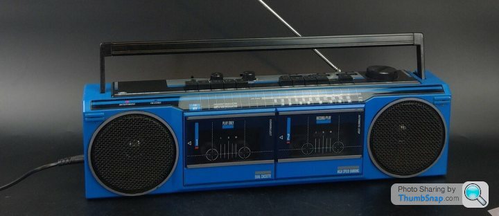
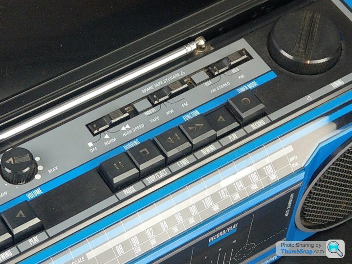
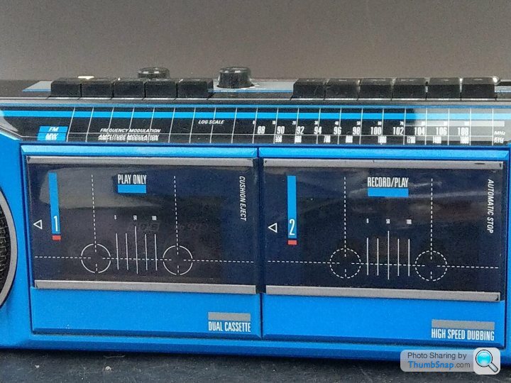
All of a sudden, taping the Sunday evening chart show was a thing and I religiously made mix tapes each week from the Top 40. I quickly acquired a cheap walkman (sadly I can't remember what though) to listen to my mix tapes walking to school and so my love of audio and 'hifi' was born. I ended up keeping the Boots Radio for around 5-6 years and it was in use constantly, I absolutely loved it.
However, things change and eventually my paper round allowed me to save up enough for a basic separates system and my first foray in to CDs. Being a typical teenager, I was always looking for the next upgrade and the Boots Radio was unceremoniously sold at a car boot sale in about 1990, never to be thought of again.
Until a few months back
Nostalgia, eBay and alcohol are a fearsome combination and what should I find one random evening but a Boots SRR-77T in blue exactly like my old one and in great condition for virtually nothing. I bought it on the spot and when it duly arrived I had no idea what to do with it it sounded terrible and to make matters worse one speaker didn't work. A quick look inside and a bit of testing later I couldn't find the problem, so I quickly decided to just rip out the broken innards and do a bluetooth conversion with decent speakers and a decent amp with at least some level of audio quality.
This is where we stand as of today, I've started acquiring the bits and will be doing the build over the next few weeks. I can't find out much on the web about it, it seems Boots acquired their audio products from all sorts of companies like Philips, Pye, Thorn, Goldstar and Ferguson and it looks to have a passing resemblance to the Sharp QT-77 radio cassette player. Possibly where the 77 model number comes from, I'm not sure.
Is there any interest for me to document the build on here? Happy to oblige if there is, it's not a very well known device but might be interesting to anyone thinking of doing similar

For those interested it was a Boots SRR-77T with twin speakers (1 watt), dual cassette with high speed dubbing (gasp), and an FM/AM radio. Eight year old me literally thought I'd hit the jackpot that Christmas!


All of a sudden, taping the Sunday evening chart show was a thing and I religiously made mix tapes each week from the Top 40. I quickly acquired a cheap walkman (sadly I can't remember what though) to listen to my mix tapes walking to school and so my love of audio and 'hifi' was born. I ended up keeping the Boots Radio for around 5-6 years and it was in use constantly, I absolutely loved it.
However, things change and eventually my paper round allowed me to save up enough for a basic separates system and my first foray in to CDs. Being a typical teenager, I was always looking for the next upgrade and the Boots Radio was unceremoniously sold at a car boot sale in about 1990, never to be thought of again.
Until a few months back

Nostalgia, eBay and alcohol are a fearsome combination and what should I find one random evening but a Boots SRR-77T in blue exactly like my old one and in great condition for virtually nothing. I bought it on the spot and when it duly arrived I had no idea what to do with it
 it sounded terrible and to make matters worse one speaker didn't work. A quick look inside and a bit of testing later I couldn't find the problem, so I quickly decided to just rip out the broken innards and do a bluetooth conversion with decent speakers and a decent amp with at least some level of audio quality.
This is where we stand as of today, I've started acquiring the bits and will be doing the build over the next few weeks. I can't find out much on the web about it, it seems Boots acquired their audio products from all sorts of companies like Philips, Pye, Thorn, Goldstar and Ferguson and it looks to have a passing resemblance to the Sharp QT-77 radio cassette player. Possibly where the 77 model number comes from, I'm not sure.
Is there any interest for me to document the build on here? Happy to oblige if there is, it's not a very well known device but might be interesting to anyone thinking of doing similar

Sounds good. I've built a couple of Ammo box boom boxes and built and modified various speaker enclosures.
I'd use something like a 2-channel TPA3116 based class D amplifier board with on-board Bluetooth.
-A 12V power supply will probably give enough power, but many similar amps will take up to 24V.
Using on-board batteries will obviously reduce internal volume.
You don't need to spend a fortune on speakers (what size are they?), but seal them in well and make the speaker enclosures bigger (desirable) by removing the cassette mechanisms and boxing-in the speakers, adding some internal sound deadening and foam. Stiffen up the casing with some internal bracing. the amplifier can sit inside a speaker enclosure.
You could try incorporating bass ports on the side/rear, but this won't necessarily give an improvement and could sound worse.
Edited by MC Bodge on Tuesday 5th December 06:46
Would be good incorporating this little gadget:
https://www.cnet.com/tech/computing/rewind-this-ra...
https://www.cnet.com/tech/computing/rewind-this-ra...
Used to. Love the boots catalogue. Second only to argos for dreaming about all the goodies in there.
I had something similar... A Cathay twin cassette player but no high speed dubbing. Did have a 3 band graphic equaliser though so I could 'tune' the sound from s t to even s
 tter.
tter.
Wasn't loud and distorted easily.. But I loved it. I can recall listening to T'pau China in your hand over and over again on Christmas day when I got it. Heaven.
I had something similar... A Cathay twin cassette player but no high speed dubbing. Did have a 3 band graphic equaliser though so I could 'tune' the sound from s
 t to even s
 tter.
tter.Wasn't loud and distorted easily.. But I loved it. I can recall listening to T'pau China in your hand over and over again on Christmas day when I got it. Heaven.
Boom78 said:
That’s taking me back! My brother and I had the single tape deck versions. Like the OP, we thought all our Christmases had come at once. I bet if I rummage around my dads loft we’d still have them! I daren’t look though - I’d spend months up there discovering more childhood things! Thanks all, it's amazing how strong the nostalgia is  Some progress has been made, despite a trip to hospital for a knee op.
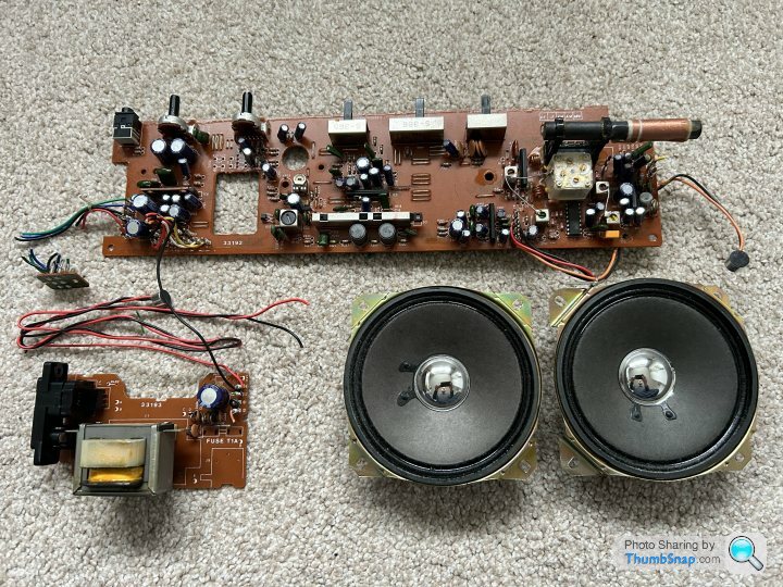
The brief here is to retain as much of the original looks of the old machine as possible so that means keeping the cassette buttons, the radio frequency dial and all the various knobs and buttons. They might not function but I want them in place regardless. Opening it up revealed this shouldn't be an issue although space is a little tight. The following stuff got removed, ie the main circuit board, all the wiring, the tinny little speakers and power supply.
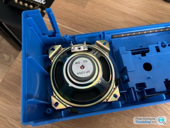
First job then was to see which speakers to go for. The choice is fairly limited due to size, both diameter and depth aren't huge. Initial thoughts were to go for the Dayton Audio CX120-8 as this is a full range dual concentric design with good reviews. Unfortunately mounting them is a problem and also the need for a crossover complicates getting it all packaged neatly. The old speakers mount on 4 corners:
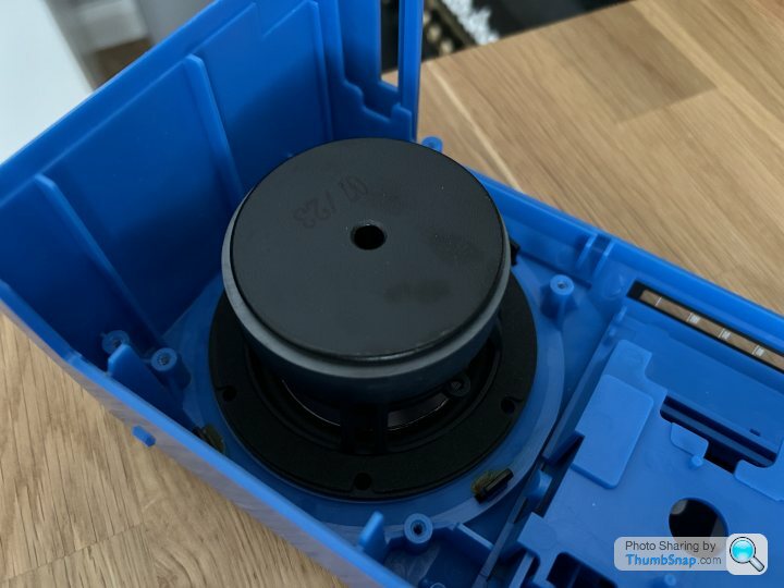
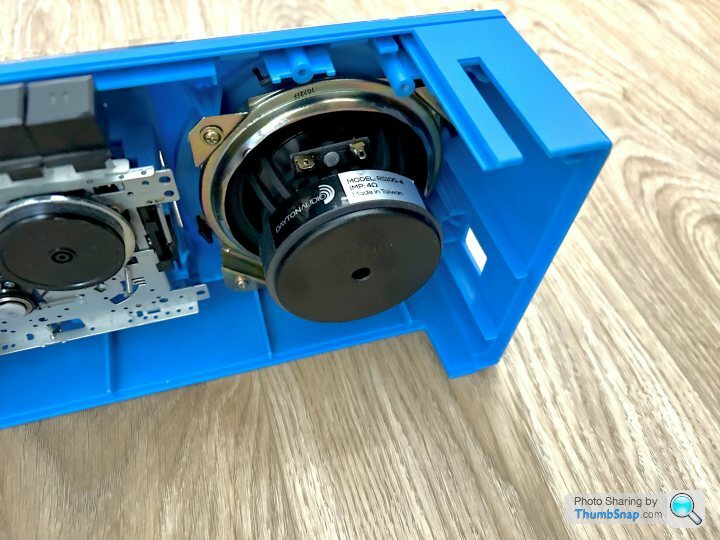
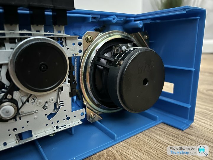
Hence, I've settled on these full range Dayton Audio RS100-4 drivers which fit really nicely and should do the job. They sit well in the cutouts and I'm going to use the frames of the old speakers to mount them. Being 4 ohms rather than 8 ohms means they're easier to drive which is a bonus.
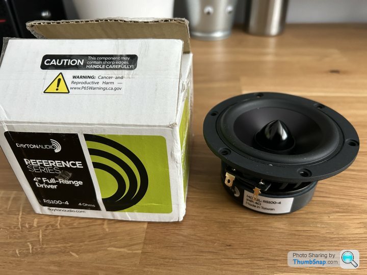
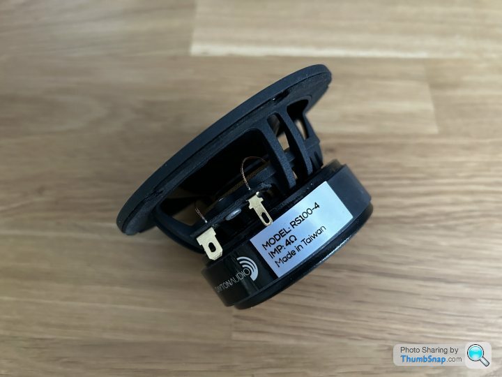
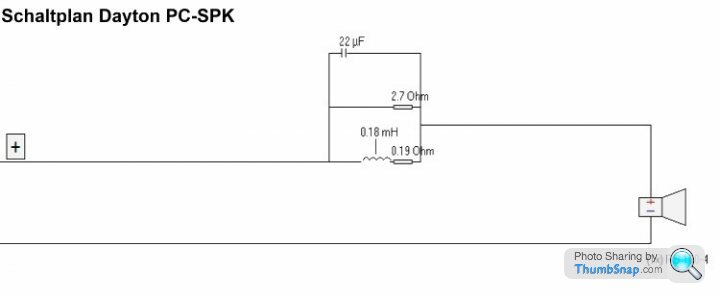
A bit of research shows that although they don't need a crossover, they do need a notch filter to sort out the treble response, luckily this is easily and cheaply achieved with a just a few components. I found the schematic on the web and duly ordered the bits.
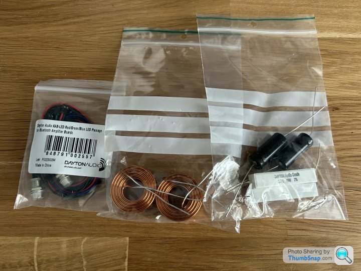
I've also settled on the amp board which is a Dayton Audio KAB 230v4. This has 2x30w with a bluetooth receiver and is based on a TPA3118 class D chip (much like MC Bodge suggested). It's a decent specc'd board and I've also bought the power supply board and all the accessory wiring kits to do it justice.
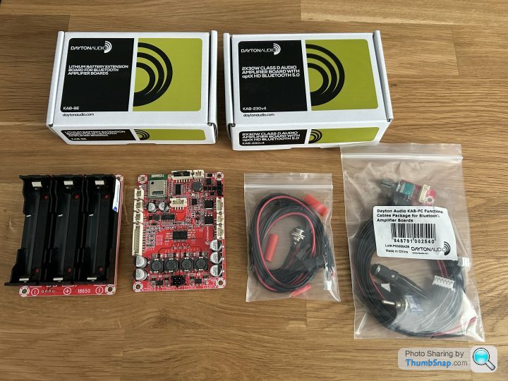
Next up is working out how to mount all the bits and package it neatly.
 Some progress has been made, despite a trip to hospital for a knee op.
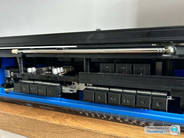
 The brief here is to retain as much of the original looks of the old machine as possible so that means keeping the cassette buttons, the radio frequency dial and all the various knobs and buttons. They might not function but I want them in place regardless. Opening it up revealed this shouldn't be an issue although space is a little tight. The following stuff got removed, ie the main circuit board, all the wiring, the tinny little speakers and power supply.

First job then was to see which speakers to go for. The choice is fairly limited due to size, both diameter and depth aren't huge. Initial thoughts were to go for the Dayton Audio CX120-8 as this is a full range dual concentric design with good reviews. Unfortunately mounting them is a problem and also the need for a crossover complicates getting it all packaged neatly. The old speakers mount on 4 corners:

Hence, I've settled on these full range Dayton Audio RS100-4 drivers which fit really nicely and should do the job. They sit well in the cutouts and I'm going to use the frames of the old speakers to mount them. Being 4 ohms rather than 8 ohms means they're easier to drive which is a bonus.


A bit of research shows that although they don't need a crossover, they do need a notch filter to sort out the treble response, luckily this is easily and cheaply achieved with a just a few components. I found the schematic on the web and duly ordered the bits.

I've also settled on the amp board which is a Dayton Audio KAB 230v4. This has 2x30w with a bluetooth receiver and is based on a TPA3118 class D chip (much like MC Bodge suggested). It's a decent specc'd board and I've also bought the power supply board and all the accessory wiring kits to do it justice.

Next up is working out how to mount all the bits and package it neatly.
Good stuff.
Those speakers look good. The Amp should work well.
Class D amps like that can be very efficient and are really compact for their output.
I would definitely be reinforcing and sealing the casing and adding some sound deadening.
I'm not sure what the specs are for these speakers, but I'd suggest that the interior is divided into two sealed compartments for the speaker enclosures. The amplifier positioned in one speaker enclosure and the power board in the other.
MC Bodge said:
Good stuff.
I would definitely be reinforcing and sealing the casing and adding some sound deadening.
I'm not sure what the specs are for these speakers, but I'd suggest that the interior is divided into two sealed compartments for the speaker enclosures. The amplifier positioned in one speaker enclosure and the power board in the other.
Agreed and it's definitely something I want to do, especially as the case is quite flimsy so it should make a difference. I just have to figure out how....any suggestions?I would definitely be reinforcing and sealing the casing and adding some sound deadening.
I'm not sure what the specs are for these speakers, but I'd suggest that the interior is divided into two sealed compartments for the speaker enclosures. The amplifier positioned in one speaker enclosure and the power board in the other.
Deranged Rover said:
Being 4 Ohm actually makes them more difficult to drive than 8 Ohm but, no matter - your amp should handle them OK.
Quite right, I blame the pain killers I'm on right now post my knee op  As you say, the amp is rated down to 4 ohms so it should be fine.
AndrewGP said:
Agreed and it's definitely something I want to do, especially as the case is quite flimsy so it should make a difference. I just have to figure out how....any suggestions?
Reinforcing the ring where the speakers are kounted, bracing corners, and maybe front to back and side to side, and lining it in places. I would remove the cassette holders and glue some stiff plastic/thin plywood sheet painted black behind the cassette windows.When the bass thumps you don't want the case flexing.
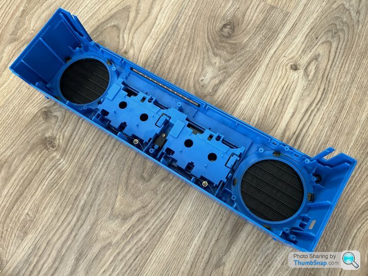
Little bit more progress today on speaker fitting, the cassette mechanism and bracing. This is the front panel:
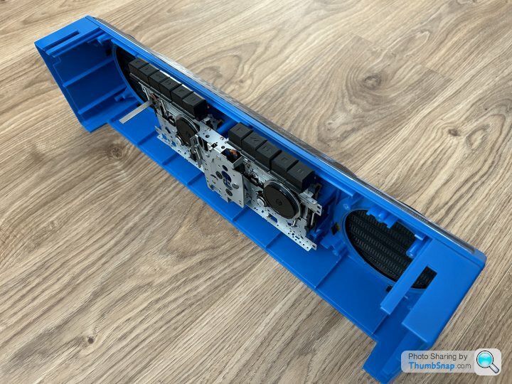
MC Bodge removing the cassette holders and gluing some black plywood sheet behind the cassette windows was my first thought too, however I may be able to get away with not doing that. The double cassette mechanism was constructed in two layers, removing the rear layer with the motor, belts and associated circuit board means the front layer is very thin. This has the advantage of retaining the buttons and their functions eg the stop button still pops open the cassette door and also means the tape heads and spindles show inside. I'm really keen to retain as much of the original look and feel as possible so keeping the insides of the cassette decks would be fantastic. I'm hopeful they'll be enough room left behind to put the battery and amp boards....time will tell.
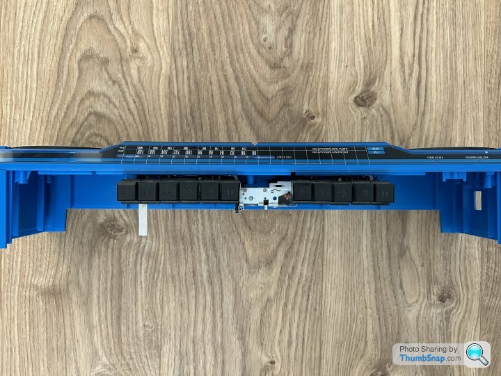
The front baffle where the speaker drivers go (if you can call it that ) is actually very stiff, surprisingly so due to the one thick ring of blue plastic inside and the black one holding the grill on the outside. The corners in this area are also quite stiff so I think I'm going to concentrate the bracing on the sides and back of the enclosure first and see how that goes.
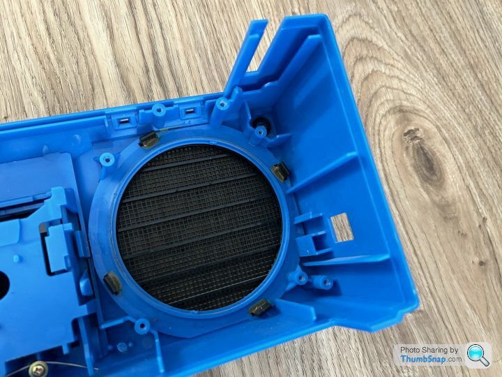
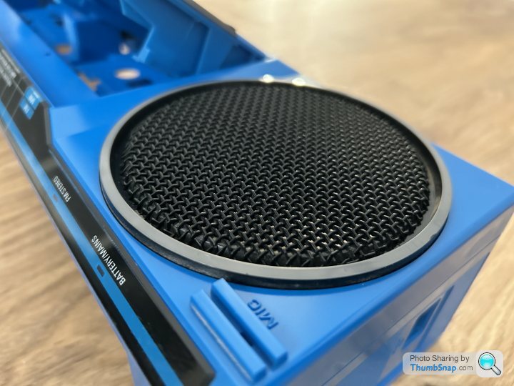
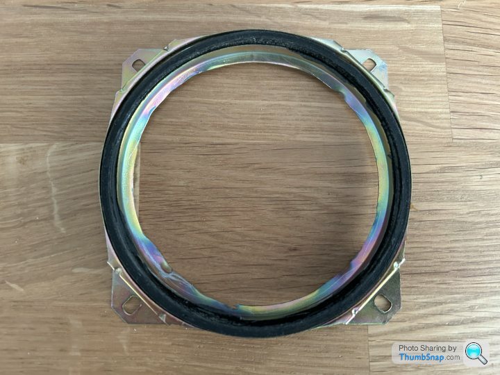
As I mentioned previously, mounting the new speaker drivers didn't look straightforward so I've used the old speakers frames to help. I simply dremeled the magnet, and support arms off and cut the cone with a scalpel to reveal the outer ring.
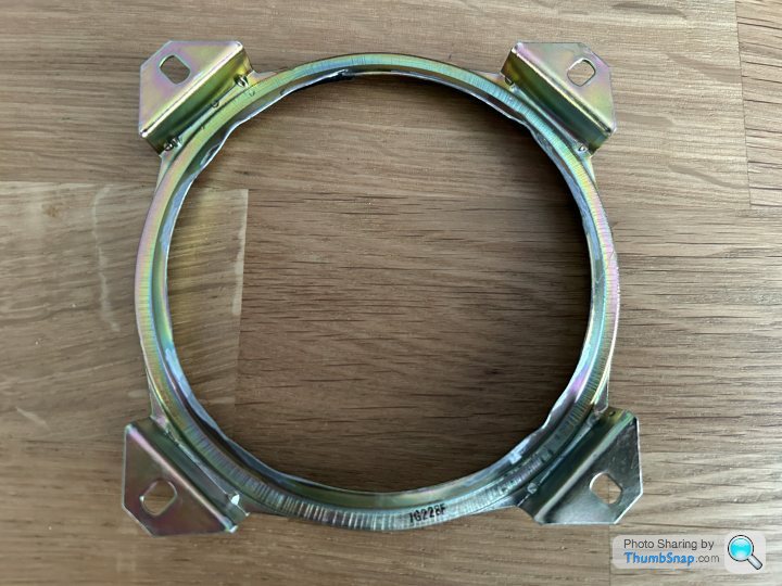
This handily has the rubber gasket still in place to clamp to the back of the new driver. A bit of filing to remove the sharp edges and the ring perfectly and securely mounts the drivers in place on the original mounting posts.

MC Bodge removing the cassette holders and gluing some black plywood sheet behind the cassette windows was my first thought too, however I may be able to get away with not doing that. The double cassette mechanism was constructed in two layers, removing the rear layer with the motor, belts and associated circuit board means the front layer is very thin. This has the advantage of retaining the buttons and their functions eg the stop button still pops open the cassette door and also means the tape heads and spindles show inside. I'm really keen to retain as much of the original look and feel as possible so keeping the insides of the cassette decks would be fantastic. I'm hopeful they'll be enough room left behind to put the battery and amp boards....time will tell.


The front baffle where the speaker drivers go (if you can call it that
 ) is actually very stiff, surprisingly so due to the one thick ring of blue plastic inside and the black one holding the grill on the outside. The corners in this area are also quite stiff so I think I'm going to concentrate the bracing on the sides and back of the enclosure first and see how that goes.

As I mentioned previously, mounting the new speaker drivers didn't look straightforward so I've used the old speakers frames to help. I simply dremeled the magnet, and support arms off and cut the cone with a scalpel to reveal the outer ring.

This handily has the rubber gasket still in place to clamp to the back of the new driver. A bit of filing to remove the sharp edges and the ring perfectly and securely mounts the drivers in place on the original mounting posts.


Love this thread. It's so niche and geeky and all the better for it 
As somebody with zero patience or finesse, all I know is that every one of those brittle plastic panels would have been cracked, every screw lost had I got within 10 feet of it.
Look forward to seeing (and hopefully hearing!) the finished article.
As it's from your youth, have you picked your first tune to be played or do you not dare to think that far ahead yet...?
Haha! Thanks Ben, it’s definitely extremely geeky and niche, I showed my wife earlier and although she dutifully listened, I could see she was just thinking ‘WTF!?’  I’m also aware that my emotional level of involvement here won’t match anyone else’s reading this thread. That said it’s distracting me from the pain in my knee post the op and keeping me amused whilst I’m at home recovering so if it’s interesting to PH, I’m happy
First song thoughts, I hadn’t even considered that but it’s a great question. Let me have a think….
 I’m also aware that my emotional level of involvement here won’t match anyone else’s reading this thread. That said it’s distracting me from the pain in my knee post the op and keeping me amused whilst I’m at home recovering so if it’s interesting to PH, I’m happy
First song thoughts, I hadn’t even considered that but it’s a great question. Let me have a think….
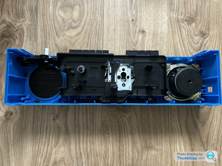
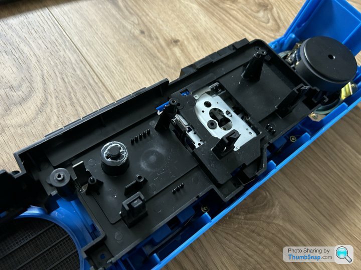
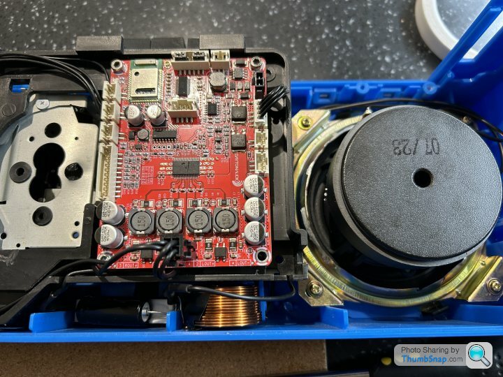
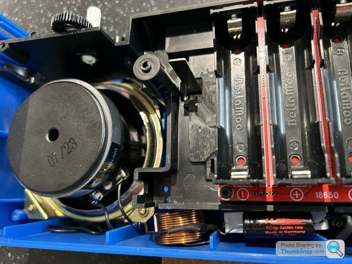
Next up was getting the amp and battery circuit boards mounted inside. After a lot of procrastination and changing my mind, I decided to try to use the plastic frame as it helps supports the tape mechanism, something I'm keen to retain as it keeps the original looks. This frame acts a 'bridge' between the front and rear parts of the case (and originally housed the main circuit board) so keeping it also helps the case's rigidity, secures what's left of the tape bits and the FM frequency dial and also gives me a platform to mount the new circuit boards. The frame and the rear case look like this.
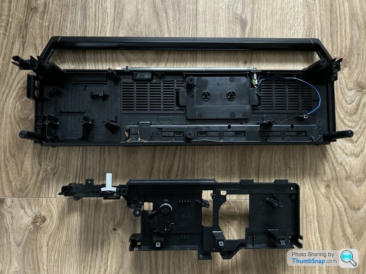
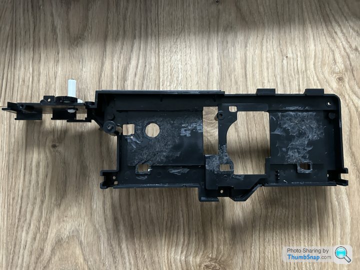
A bit of mocking up showed the concept should work, so out came the dremel to remove the bits of the frame getting in the way and to free up the space needed. It's amazing how well the boards fit and this placement has the added benefit of the ventilation grills on the back of the case are in the same position.
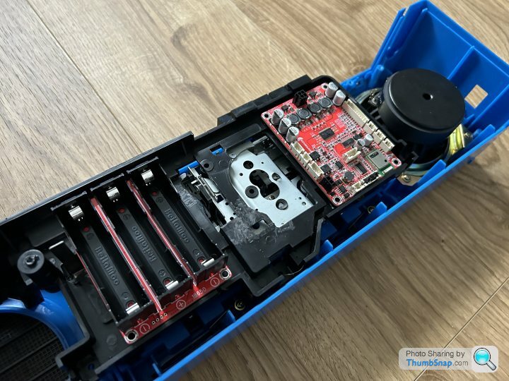
The disadvantage of doing it this way though is there's virtually no way to separate the speaker enclosures from each other as it's incredibly tight in there. Hopefully this won't be an issue and I'll do my best to pack the insides in acoustic foam to help. I guess I'll find out how successful this will be when I test it!
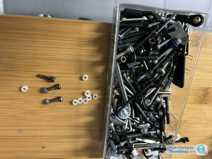
Digging through the spares box in the garage, I found some plastic spacers and the required bolts and nylocs which were used to secure the boards to the frame. The back was then trail fitted and to check the clearances which all looked good.
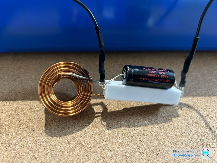
Next, the notch filters were soldered up. This consists of a capacitor, resistor and inductor in series and takes out a peak in the treble response above about 10Khz. I can't stand bright speakers and this filter (apparently) provides a nice flat frequency response. Once soldered up, these were tucked out the way at the bottom of the case and the speaker wires soldered on to the terminals.
The amp board has an optional volume control. I've no idea if I would actually use this, but I liked the idea of fitting this to the original volume knob. Through no forward planning and a lot of luck, this was quite easy to achieve Some scrap wood was cut to form a frame and the small circuit board attached in the correct place. Amazingly the old volume knob perfectly fitted the new potentiometer so is fully functional again. The old tone knob was super-glued in place and the amp's aux in socket fitted to the now redundant headphone hole to complete the OEM look.
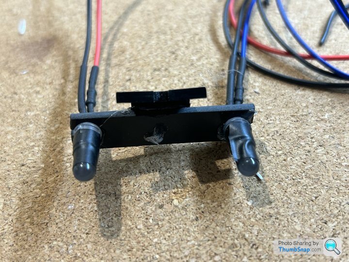
In keeping with the OEM theme, I really wanted the old power LED and FM Stereo LED on the front panel to continue to function, albeit with the Bluetooth LED to replace the FM Stereo one. However, as the old circuit board mounting these inside the case fell to bits on removal, I had to get creative and build a new one bracket. This was achieved with some scrap plastic and now sports the red power LED and blue bluetooth LED in place of the old ones. It's not a perfect fit but it's close enough and works fine.
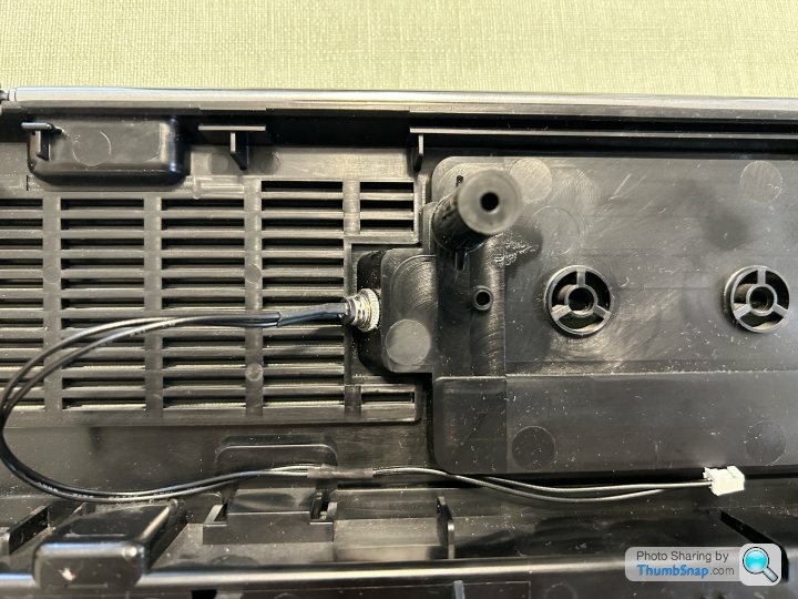
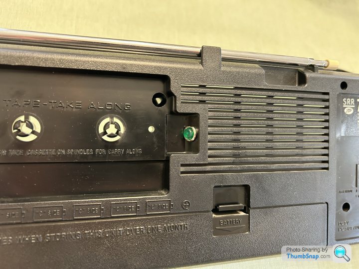
Next, the bluetooth pairing button was discretely mounted on the rear of the case out of the way. It won't be needed very often so it seems a logical place to mount it.
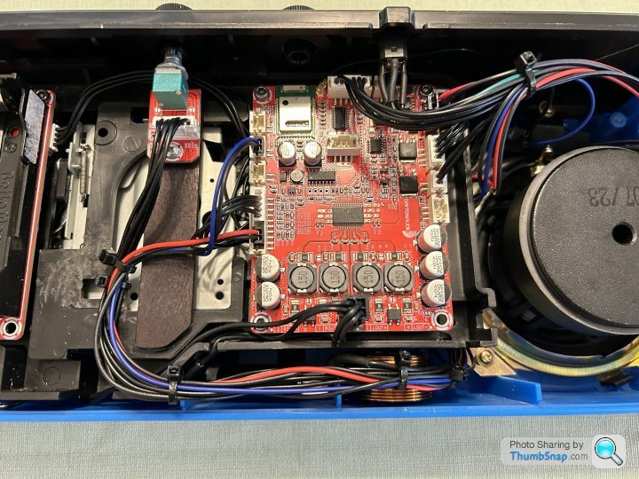
Finally, the rats nest of wires was tidied up and properly managed with cable ties to make things nice and neat. The supplied wires are all very long which makes this a bit of a challenge!
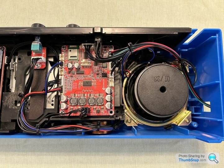
Still to do are fit the power switch, power jack and charging LED to the hole in the side of the case and then complete the bracing


A bit of mocking up showed the concept should work, so out came the dremel to remove the bits of the frame getting in the way and to free up the space needed. It's amazing how well the boards fit and this placement has the added benefit of the ventilation grills on the back of the case are in the same position.


The disadvantage of doing it this way though is there's virtually no way to separate the speaker enclosures from each other as it's incredibly tight in there. Hopefully this won't be an issue and I'll do my best to pack the insides in acoustic foam to help. I guess I'll find out how successful this will be when I test it!
Digging through the spares box in the garage, I found some plastic spacers and the required bolts and nylocs which were used to secure the boards to the frame. The back was then trail fitted and to check the clearances which all looked good.


Next, the notch filters were soldered up. This consists of a capacitor, resistor and inductor in series and takes out a peak in the treble response above about 10Khz. I can't stand bright speakers and this filter (apparently) provides a nice flat frequency response. Once soldered up, these were tucked out the way at the bottom of the case and the speaker wires soldered on to the terminals.


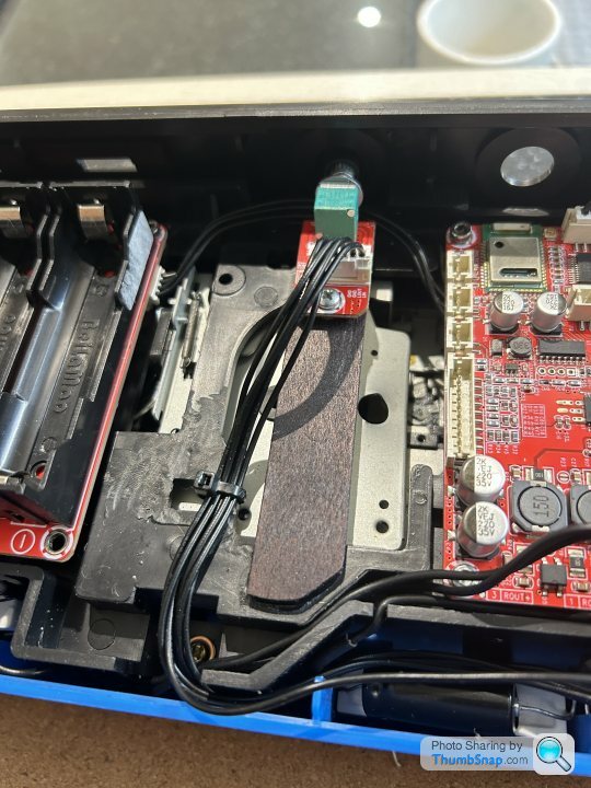
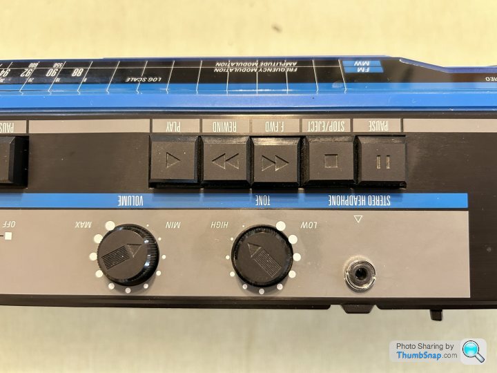
The amp board has an optional volume control. I've no idea if I would actually use this, but I liked the idea of fitting this to the original volume knob. Through no forward planning and a lot of luck, this was quite easy to achieve
 Some scrap wood was cut to form a frame and the small circuit board attached in the correct place. Amazingly the old volume knob perfectly fitted the new potentiometer so is fully functional again. The old tone knob was super-glued in place and the amp's aux in socket fitted to the now redundant headphone hole to complete the OEM look.

In keeping with the OEM theme, I really wanted the old power LED and FM Stereo LED on the front panel to continue to function, albeit with the Bluetooth LED to replace the FM Stereo one. However, as the old circuit board mounting these inside the case fell to bits on removal, I had to get creative and build a new one bracket. This was achieved with some scrap plastic and now sports the red power LED and blue bluetooth LED in place of the old ones. It's not a perfect fit but it's close enough and works fine.

Next, the bluetooth pairing button was discretely mounted on the rear of the case out of the way. It won't be needed very often so it seems a logical place to mount it.


Finally, the rats nest of wires was tidied up and properly managed with cable ties to make things nice and neat. The supplied wires are all very long which makes this a bit of a challenge!


Still to do are fit the power switch, power jack and charging LED to the hole in the side of the case and then complete the bracing

Gassing Station | Home Cinema & Hi-Fi | Top of Page | What's New | My Stuff


