Orlandoo Hunter OH32M02 build thread
Discussion
Hello! I thought people might like to see this. I've built Tamiya stuff before (Frog, Wild Willy, Bigwig) but I wanted something smaller and more indoor-friendly. These looked good, and obviously the smart thing to do is go for the most complicated one first.
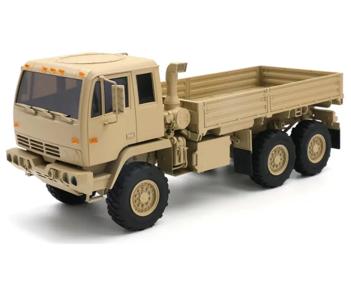
Anyways, this is a 1/32 scale RC 6x6 truck. Here's what the finished thing should look like (except I'm painting mine orange and black).
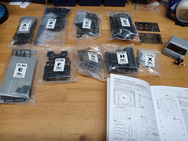
Here's what you get in the box. Lego Jules Verne for scale.
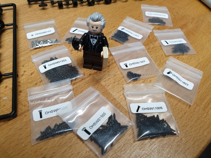
Here's Jules with the teeny little bags of screws. At this point I'm a bit concerned about my fingers; I'd never previously regarded them as particularly sausage-like, but some of the screws really are rather small.
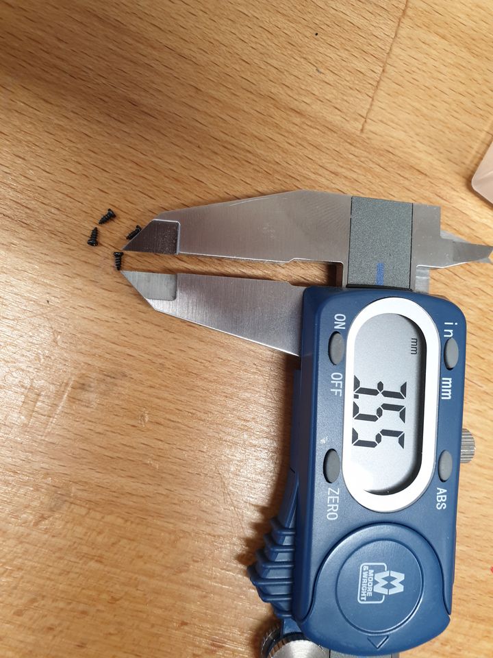
And here's a typical screw. There are some slightly bigger ones, but there are also some even smaller ones.
Anyways, this is a 1/32 scale RC 6x6 truck. Here's what the finished thing should look like (except I'm painting mine orange and black).
Here's what you get in the box. Lego Jules Verne for scale.
Here's Jules with the teeny little bags of screws. At this point I'm a bit concerned about my fingers; I'd never previously regarded them as particularly sausage-like, but some of the screws really are rather small.
And here's a typical screw. There are some slightly bigger ones, but there are also some even smaller ones.
First thing is to make the axles. No differentials (that would have been funny).
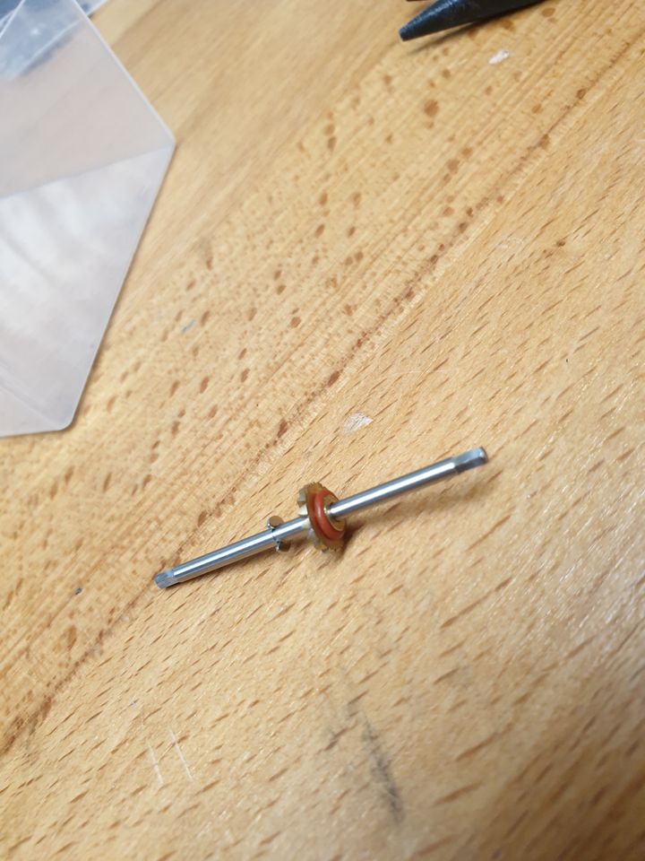
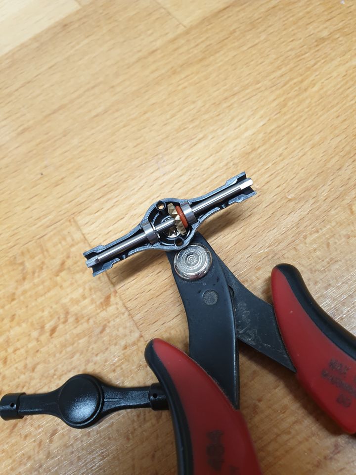
They go into their housings (eleven pieces so far for this one):
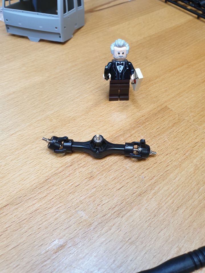
Then another twenty five bits and you've got the front axle partly built. Jules is suitably impressed.
Then you fold these bits, and discover that two sprues didn't come out right. You wait 7 weeks for replacements from Hong Kong.
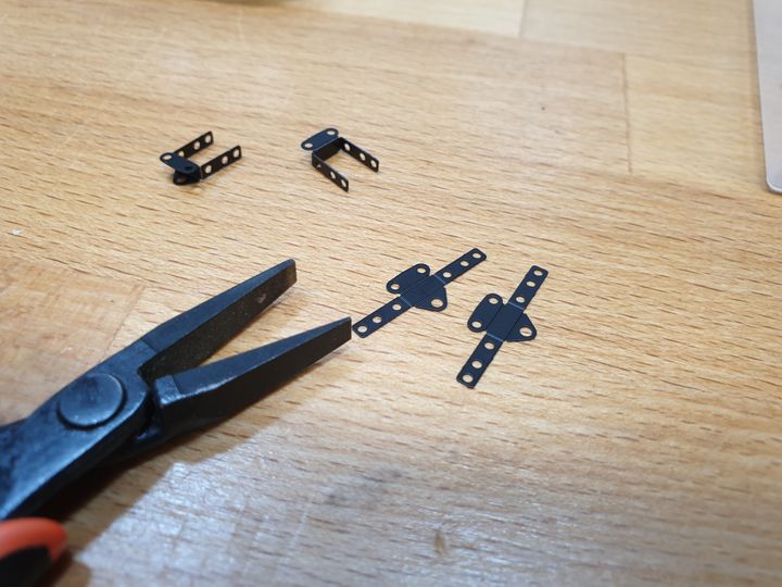
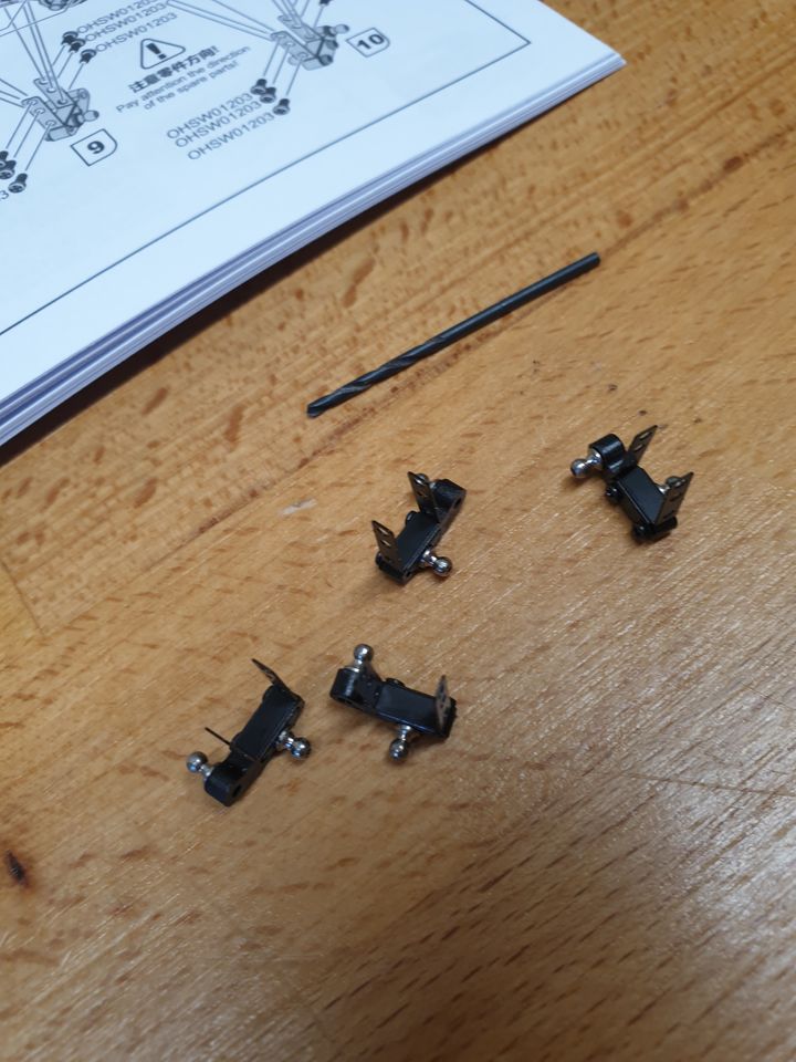
The replacements arrive and you make these teeny little things, wondering what they're for (I think they attach the suspension to the axles but we'll probably find out later). The little ball bits need their holes very carefully opening with a drill bit so that the threads bite into the plastic.
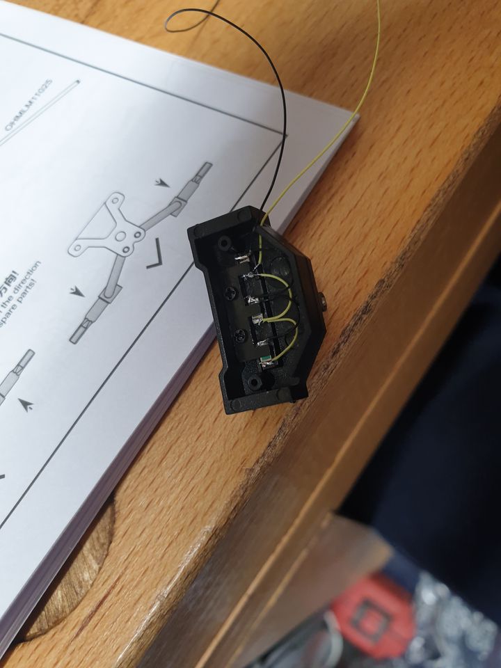
Then you have the fun of wiring up SMD LEDs. The first three took me about an hour, and I used to do a lot of small soldering. I think there are twenty-one more to do.
Then you realise you forgot to take pictures of a couple of stages and suddenly you're assembling the main ladder chassis, onto which the motor and servo and various other bits attach. Jules turns up to check out how his ride is coming along.
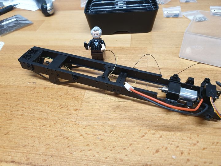
That's how far along I am so far. More as I do it, if anyone's interested. It is very fiddly indeed.
They go into their housings (eleven pieces so far for this one):
Then another twenty five bits and you've got the front axle partly built. Jules is suitably impressed.
Then you fold these bits, and discover that two sprues didn't come out right. You wait 7 weeks for replacements from Hong Kong.
The replacements arrive and you make these teeny little things, wondering what they're for (I think they attach the suspension to the axles but we'll probably find out later). The little ball bits need their holes very carefully opening with a drill bit so that the threads bite into the plastic.
Then you have the fun of wiring up SMD LEDs. The first three took me about an hour, and I used to do a lot of small soldering. I think there are twenty-one more to do.
Then you realise you forgot to take pictures of a couple of stages and suddenly you're assembling the main ladder chassis, onto which the motor and servo and various other bits attach. Jules turns up to check out how his ride is coming along.
That's how far along I am so far. More as I do it, if anyone's interested. It is very fiddly indeed.
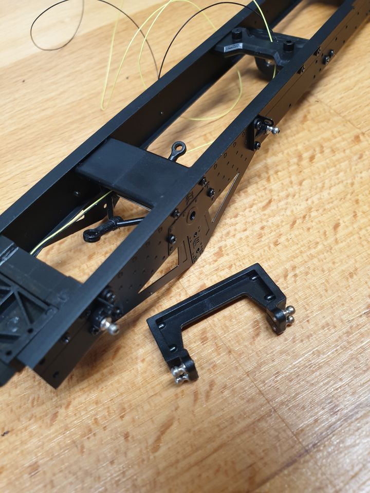
Progress! First bit today is fitting eight more of the little ball-joint things to the chassis and this bit, which then screws into the chassis. As before, I used a 2mm drill bit (just in fingers) to very slightly open the start of the hole in the plastic so the threads have something to bite into, then needle-nose pliers to twist the ball bit in. No swearing at all for these.
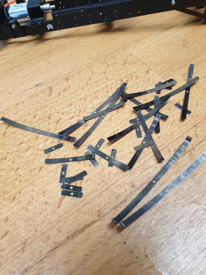
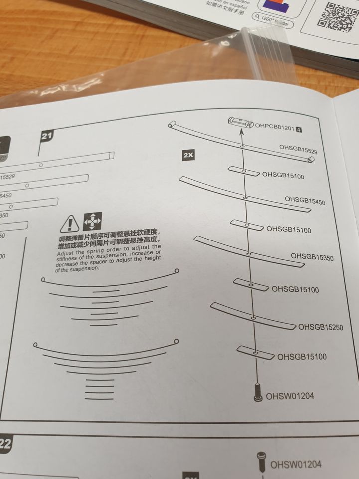
Next these bits get turned into the leaf springs. The instructions show two different ways to assemble them depending on how stiff you want them. I like my suspension plump, not firm, so the bigger leaves have the smaller ones between them (this'll make sense when you see the instructions).
The instructions showing the two orders to put the leaves:
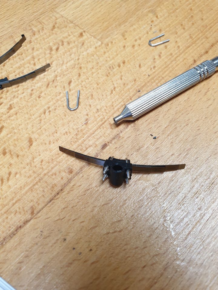
Then one set of them gets assembled into a bigger, erm, assembly. The nuts are miniscule - less than a millimetre long and wide. The kit comes with a little nut spinner for them. I managed to drop one and spent a happy ten minutes looking under and around the bench as I'm not sure you get spares...
Last bit so far is to assemble the shock absorbers. The end bit (bottom of the picture) screws onto the thread of the metal rod bit, so again I opened it out a little, but this time with a 1.5mm bit. Six of these to make, I've done three so far.

I do need to think a bit more about what bits I want to paint orange, and what I want to leave black and/or grey. The cab is painted, as is the bed (and its sides). Not sure about the wheels and various other bits.
Next these bits get turned into the leaf springs. The instructions show two different ways to assemble them depending on how stiff you want them. I like my suspension plump, not firm, so the bigger leaves have the smaller ones between them (this'll make sense when you see the instructions).
The instructions showing the two orders to put the leaves:
Then one set of them gets assembled into a bigger, erm, assembly. The nuts are miniscule - less than a millimetre long and wide. The kit comes with a little nut spinner for them. I managed to drop one and spent a happy ten minutes looking under and around the bench as I'm not sure you get spares...
Last bit so far is to assemble the shock absorbers. The end bit (bottom of the picture) screws onto the thread of the metal rod bit, so again I opened it out a little, but this time with a 1.5mm bit. Six of these to make, I've done three so far.
I do need to think a bit more about what bits I want to paint orange, and what I want to leave black and/or grey. The cab is painted, as is the bed (and its sides). Not sure about the wheels and various other bits.
Did about another hour today (including rebuilding those U-links around the leaf springs because I'd left out four little metal plates to spread the load from the nuts).
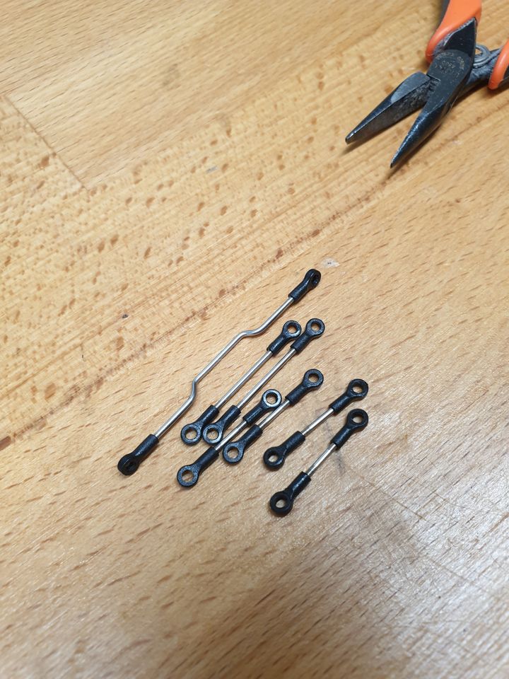
First step is to make up a load of little link bars - these are for the steering and the suspension. Not too tricky, though they have to be rather specific lengths when finished (four are "about 7mm", one is "14.2mm"). The wiggly one arrives straight - you have to bend it as per a 1:1 drawing in the instructions, which is a bit fiddly (apologies for using that word a lot) but more straightforward than I'd expected. You do need two fairly small pliers for that - I have some nice little Bahco ones, but a jewellery-making set would do perfectly well for a lot less money.
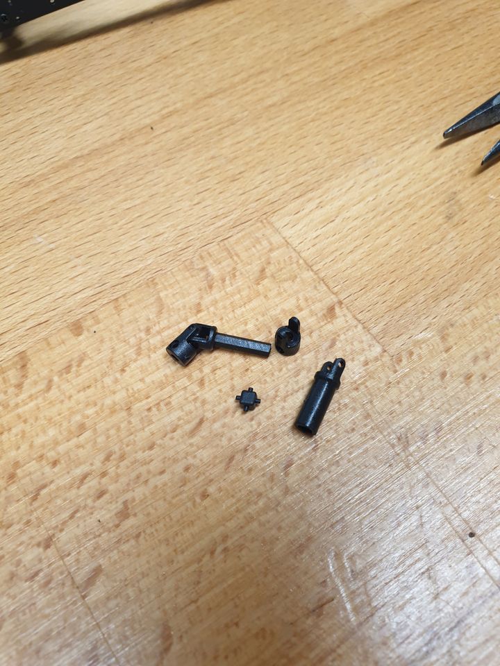
Next the four driveshafts. Quite a few reviews suggest swapping these for the metal upgrades for strength and longevity - having built them, I'd say buy the metal ones so you don't have to assemble these! These are the bits for each - the shafts vary in length but the other bits are consistent:
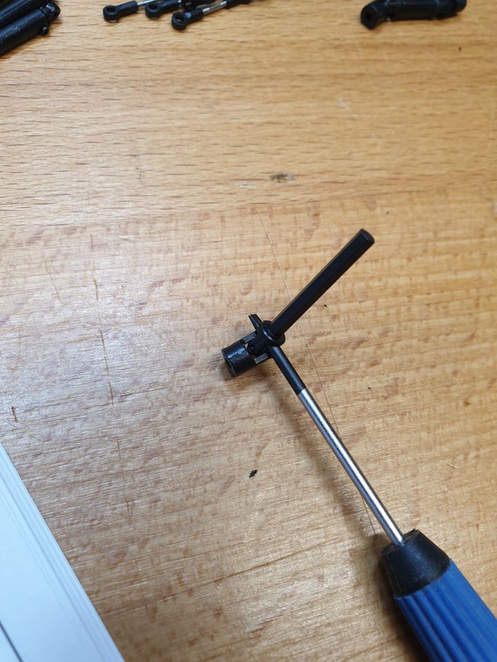
Here's how I assembled them - get the square bit with the pegs into the shaft end, then jam a precision screwdriver in to stop it rotating, and get the other end on. That worked pretty well.
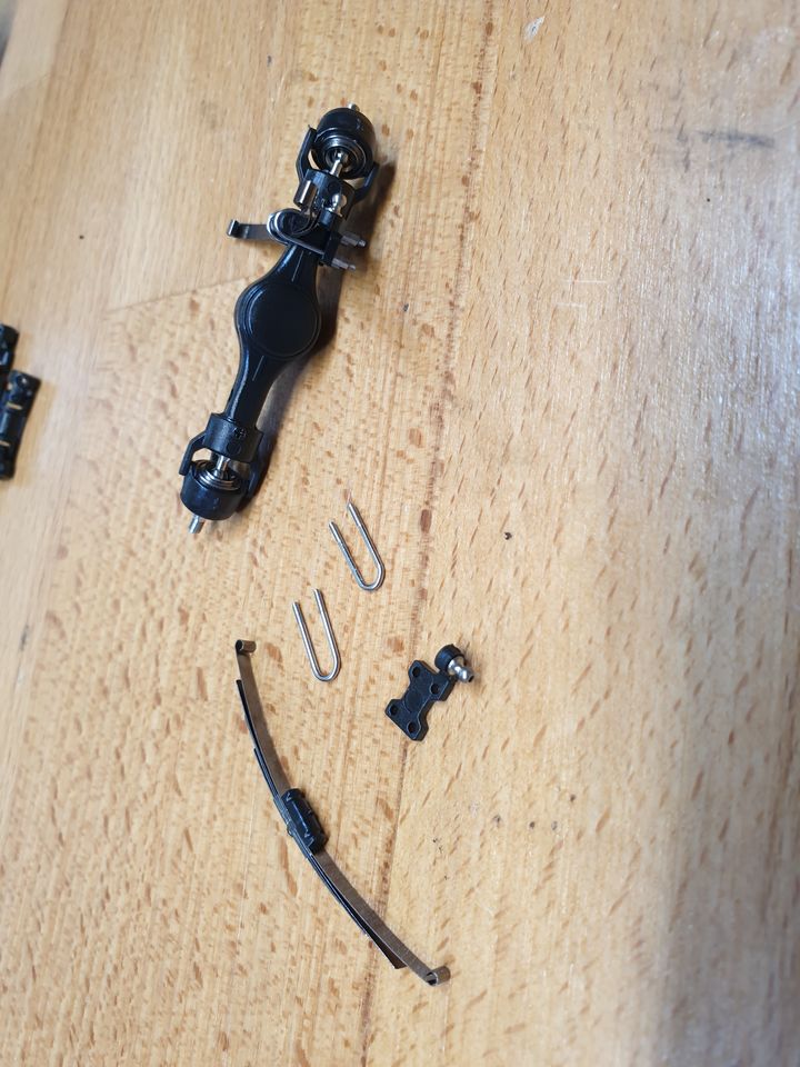
Next stage is to finish building the front axle. Four more U-links, sixteen of the teeny nuts, no swearing but a few "oh, come on!"s.
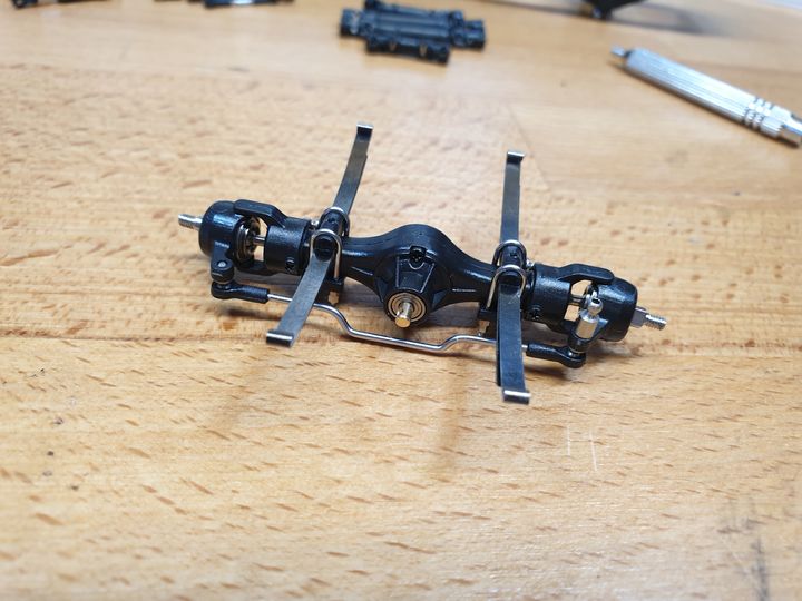
And assembled with the steering link:
That's probably it for today because I have quite sore fingers from the drive shafts. I did add the suspension hangers to the chassis, so next step is to fix the front axle in place. I should point out that I am actually quite enjoying this, in case it seems like a non-stop moanfest about how small everything is.
First step is to make up a load of little link bars - these are for the steering and the suspension. Not too tricky, though they have to be rather specific lengths when finished (four are "about 7mm", one is "14.2mm"). The wiggly one arrives straight - you have to bend it as per a 1:1 drawing in the instructions, which is a bit fiddly (apologies for using that word a lot) but more straightforward than I'd expected. You do need two fairly small pliers for that - I have some nice little Bahco ones, but a jewellery-making set would do perfectly well for a lot less money.
Next the four driveshafts. Quite a few reviews suggest swapping these for the metal upgrades for strength and longevity - having built them, I'd say buy the metal ones so you don't have to assemble these! These are the bits for each - the shafts vary in length but the other bits are consistent:
Here's how I assembled them - get the square bit with the pegs into the shaft end, then jam a precision screwdriver in to stop it rotating, and get the other end on. That worked pretty well.
Next stage is to finish building the front axle. Four more U-links, sixteen of the teeny nuts, no swearing but a few "oh, come on!"s.
And assembled with the steering link:
That's probably it for today because I have quite sore fingers from the drive shafts. I did add the suspension hangers to the chassis, so next step is to fix the front axle in place. I should point out that I am actually quite enjoying this, in case it seems like a non-stop moanfest about how small everything is.
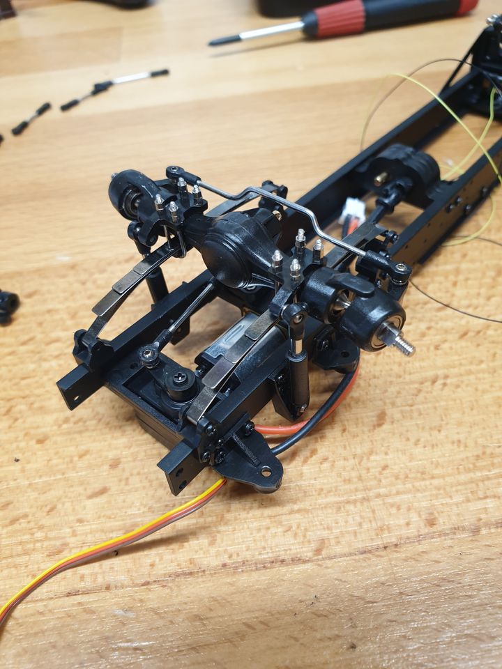
Just a minor update. Got the front axle mounted (the leaf springs close up once there's even a teeny bit of weight on them):
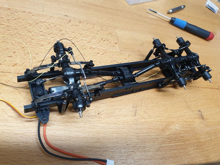
...and both rears:
But the next stage has four more teeny SMD LEDs, and the tip on my soldering iron is a bit chunky for this work so I've ordered some much pointier ones. And a pin vice for the drill bits as there'll be a load more for them to do.

To make it almost doable I've put some double-sided tape on a bit of ply, marked the spacing for the holes the LEDs are going into, and stuck them onto the tape. It'll still be a fiddle but not nearly as hard as trying to do it freehand.
...and both rears:
But the next stage has four more teeny SMD LEDs, and the tip on my soldering iron is a bit chunky for this work so I've ordered some much pointier ones. And a pin vice for the drill bits as there'll be a load more for them to do.
To make it almost doable I've put some double-sided tape on a bit of ply, marked the spacing for the holes the LEDs are going into, and stuck them onto the tape. It'll still be a fiddle but not nearly as hard as trying to do it freehand.
I got another hour or so in today - decided not to wait for the new soldering iron tips because I found a pack of old ones, and my pin vice (which I'm not sure I'll need any more) arrived, and I found the really skinny solder I used to use for fiddly stuff.
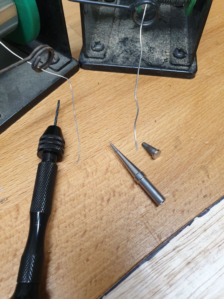
Those of you smarter and/or more observant than me will have spotted that the new tip doesn't actually have the same fitting, so instead I gave the old one a good going with some tip cleaner and pressed on - it worked pretty well, and I've got the hang of soldering the teeny wires to the LEDs. Another four done, seventeen (I think) more to go. Annoyingly I just noticed that the LED breakout board is common +ve, not common -ve. If I'd spotted that sooner I could have been more cunning with the wiring, particularly the long back-to-front runs (the controller will sit in the cab at the front).
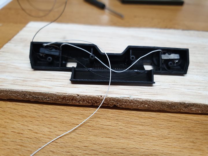
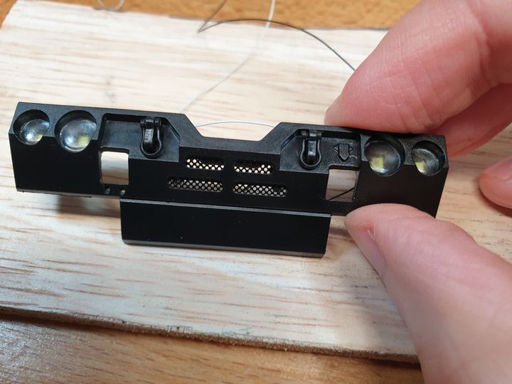
Anyways, getting the hang of it; the front bumper is done.
Did two more LEDs and assembled the back left bumper/light cluster too, but I don't have a photo of that yet. Back right has three LEDs, all on different circuits (indicator, rear/brake, and reverse).
Those of you smarter and/or more observant than me will have spotted that the new tip doesn't actually have the same fitting, so instead I gave the old one a good going with some tip cleaner and pressed on - it worked pretty well, and I've got the hang of soldering the teeny wires to the LEDs. Another four done, seventeen (I think) more to go. Annoyingly I just noticed that the LED breakout board is common +ve, not common -ve. If I'd spotted that sooner I could have been more cunning with the wiring, particularly the long back-to-front runs (the controller will sit in the cab at the front).
Anyways, getting the hang of it; the front bumper is done.
Did two more LEDs and assembled the back left bumper/light cluster too, but I don't have a photo of that yet. Back right has three LEDs, all on different circuits (indicator, rear/brake, and reverse).
Edited by Sporky on Sunday 10th November 16:13
I built the other back bumper. If you're doing this, put in a much longer link between the brake/back lights. Also wire the whole thing as common +VE, it'll be much easier. This is the rat's nest I ended up with, and every black - VE wire has to be paired with the right coloured +VE wire, so I put a tiny bit of sleeving over each pair. Still tricky. Also remember to test each LED as you do it, because getting them back out isn't easy.
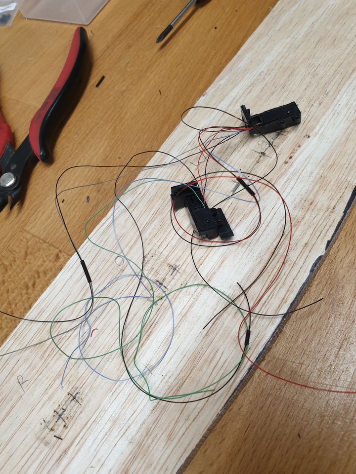
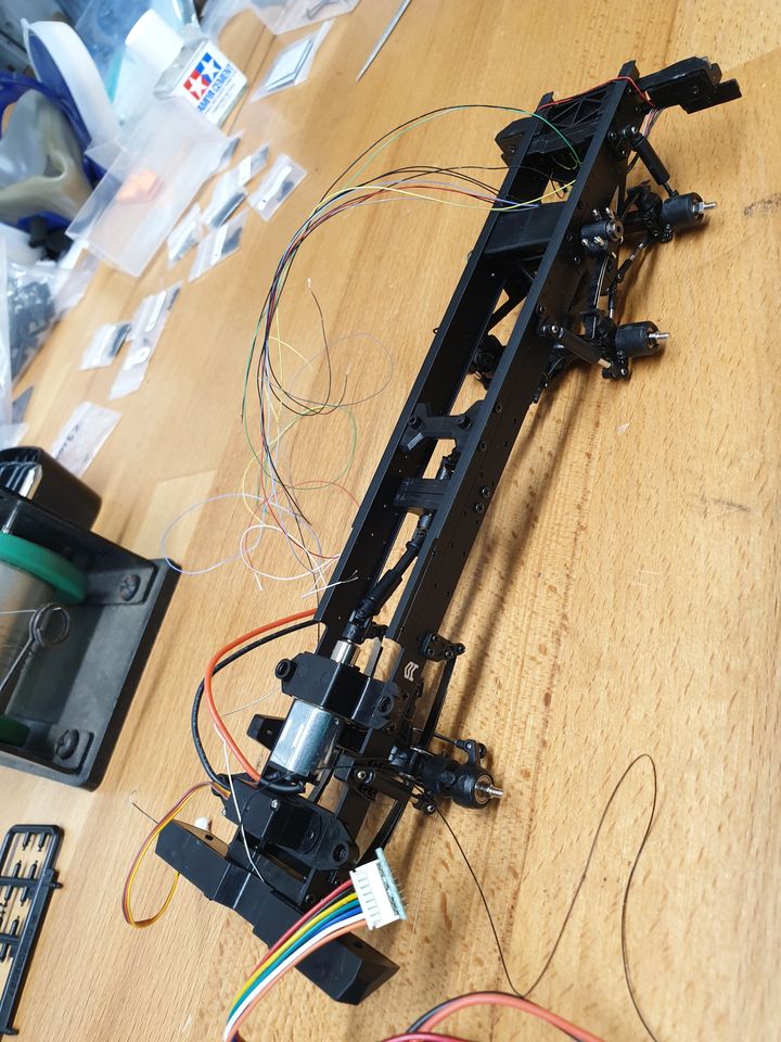
And if you thought that was bad, here's with the bumpers in place and the wires partly threaded through the chassis. I'll put all of these through some more tubing to keep them neat, and I've written down what each colour is for (most are obvious, but bLue is left indicator, gReen is right, grey is reverse).
Two of the bits of sleeving came off while doing this so I had to retest again, and you may be able to see where the brake light connector wires are stretched tight over the top of the chassis - not perfect, but it does all work.
New soldering iron bits finally arrived, though I've been doing fine with the old one since giving it a clean.
Yesterday was mostly putting together the "model" bits - exhaust stack, fuel tank, and so on. Photos later. That will continue today. I'm off work next week so should make a good bit of progress.
Yesterday was mostly putting together the "model" bits - exhaust stack, fuel tank, and so on. Photos later. That will continue today. I'm off work next week so should make a good bit of progress.
So first I made these out of bits.
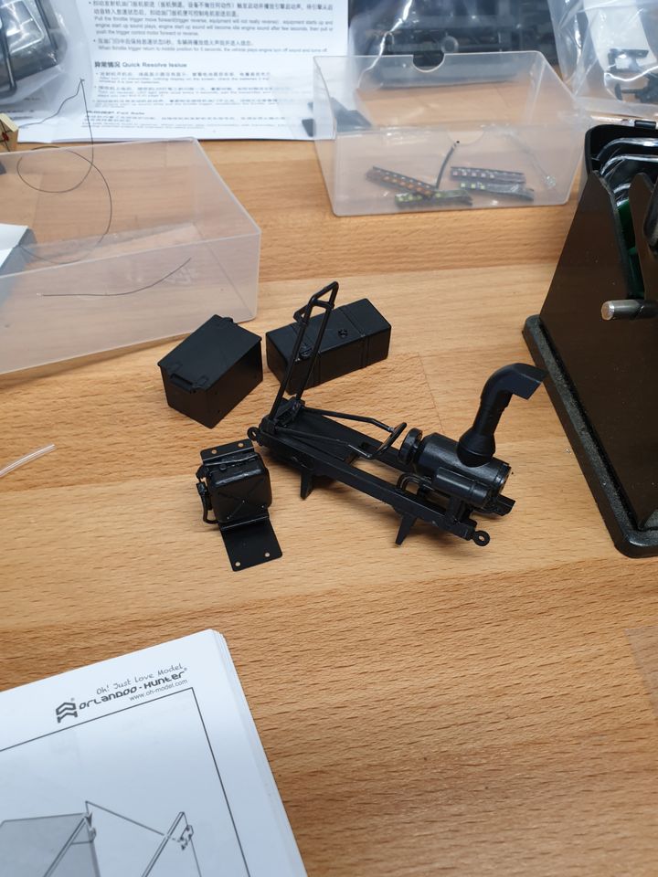
Then it occurred to me that I could make things neater and simpler by running all the wires through a bit of clear heat-shrink (which I have not shrunk). Also you can see where the winch is attached on the side. You can extend and retract it. Play value!

And then I attached the bits I'd made to the chassis:
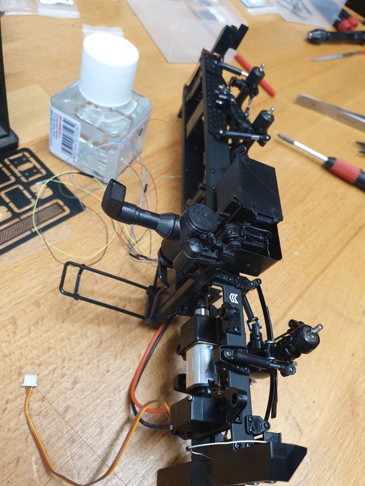
And a shot from the other end - this is about where I got to. Bodywork starts going on next, and I need to check all the LEDs again to make sure I re-paired the wires right.
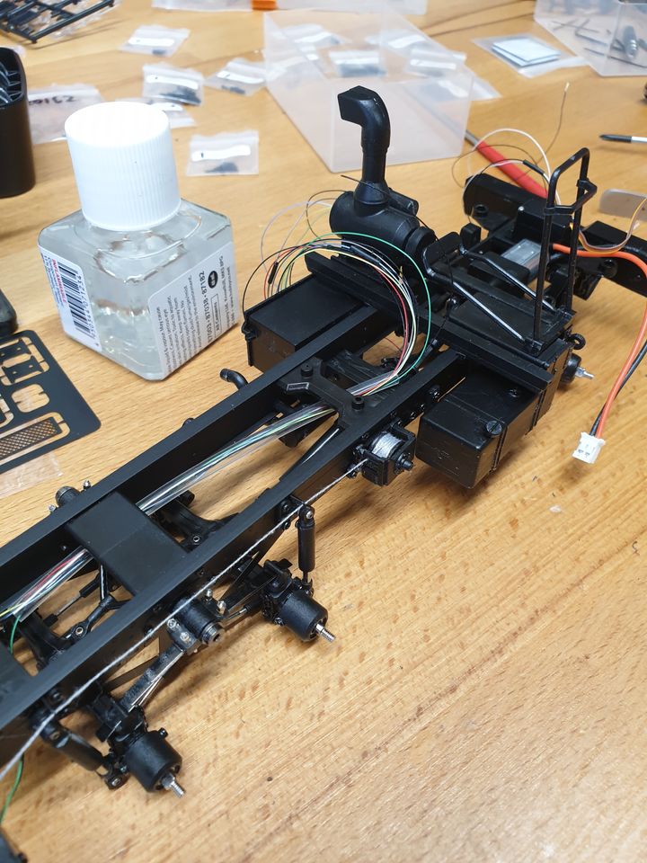
Then it occurred to me that I could make things neater and simpler by running all the wires through a bit of clear heat-shrink (which I have not shrunk). Also you can see where the winch is attached on the side. You can extend and retract it. Play value!
And then I attached the bits I'd made to the chassis:
And a shot from the other end - this is about where I got to. Bodywork starts going on next, and I need to check all the LEDs again to make sure I re-paired the wires right.
So. Turns out my suspicion that I'd knackered the wiring putting the back together was right. Fortunately there was enough left on each side to splice in an extra bit, and the kit comes with some tiny heatshrink so it's pretty much the perfect crime. I seem to have remembered how to solder.
It's a bit irksome that they've put no thought at all into how you're meant to route all the wires around, because this could easily have been avoided with better kit design.
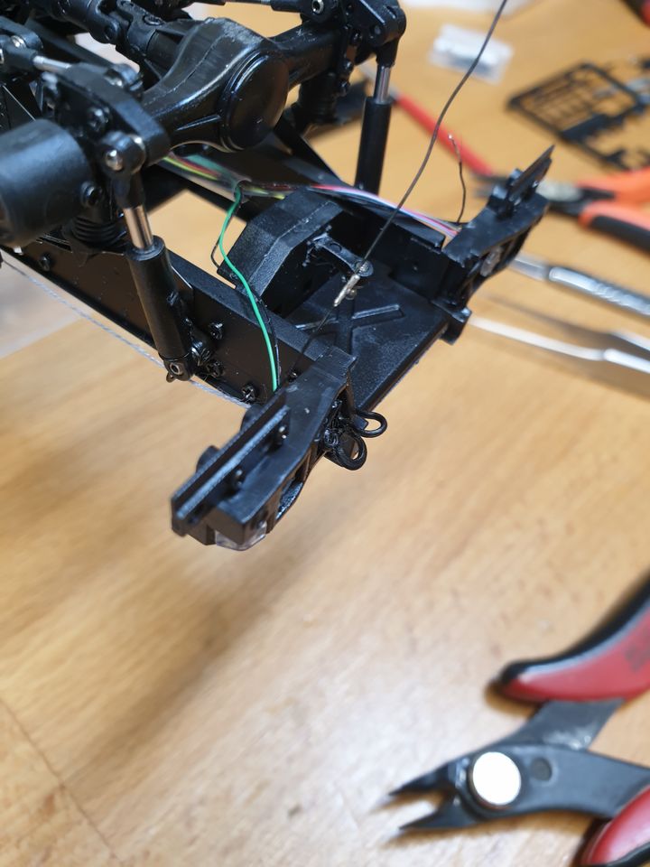
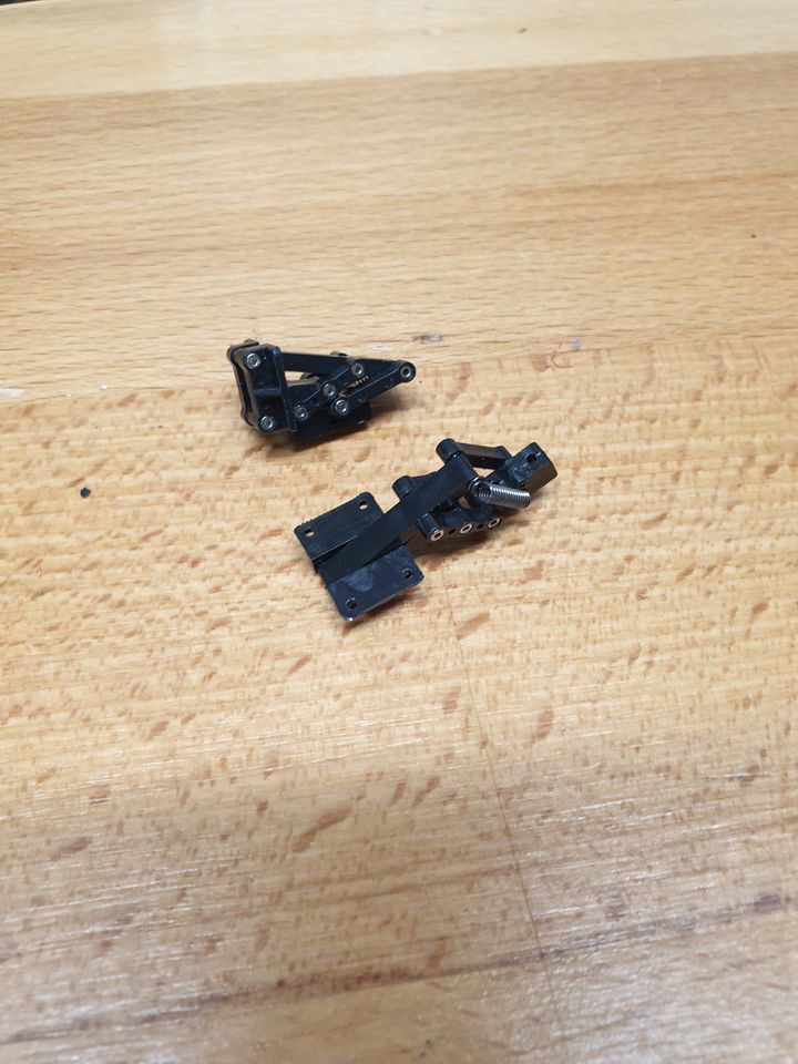
Next is assembling the hinges that attach the cab (so you can tilt it to get at the electronics stuff). Lots and lots of bits, and another load of machine-screw threaded fixings going into ABS, so I redrilled the holes at 1mm and then used the fixings in a pin vice (which I now very puffy heart love) to tap threads in.
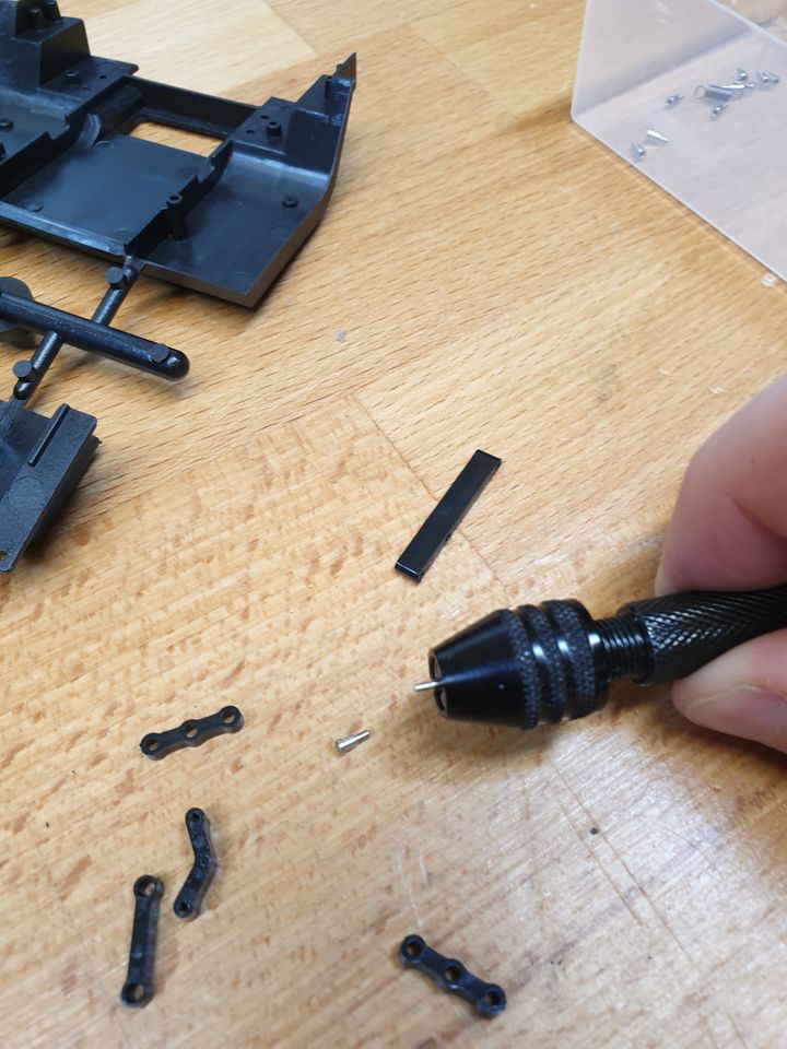
And assembled, one open, one closed.
Not shown is the flatbed which I've (I think) now glued together. I made the mistake of painting the bits on the sprue thinking it'd be easier, but the glue just lifts the paint so it all needs respraying. This bit nearly resulted in swearing.
Finally for today I started assembling the cab base, but there's a bit where you have to assemble four tiny bits of laser-cut metal together and I stopped just as I was reaching for a hammer to smash it all up after they popped back apart for the nth time. They're the little steps to get up into the cab, and as I don't intend to shrink myself to minifig size I may just pretend they don't exist. Needlessly fiddly, even in the context of the model as a whole.
On the bright side, only eight more pages.
It's a bit irksome that they've put no thought at all into how you're meant to route all the wires around, because this could easily have been avoided with better kit design.
Next is assembling the hinges that attach the cab (so you can tilt it to get at the electronics stuff). Lots and lots of bits, and another load of machine-screw threaded fixings going into ABS, so I redrilled the holes at 1mm and then used the fixings in a pin vice (which I now very puffy heart love) to tap threads in.
And assembled, one open, one closed.
Not shown is the flatbed which I've (I think) now glued together. I made the mistake of painting the bits on the sprue thinking it'd be easier, but the glue just lifts the paint so it all needs respraying. This bit nearly resulted in swearing.
Finally for today I started assembling the cab base, but there's a bit where you have to assemble four tiny bits of laser-cut metal together and I stopped just as I was reaching for a hammer to smash it all up after they popped back apart for the nth time. They're the little steps to get up into the cab, and as I don't intend to shrink myself to minifig size I may just pretend they don't exist. Needlessly fiddly, even in the context of the model as a whole.
On the bright side, only eight more pages.
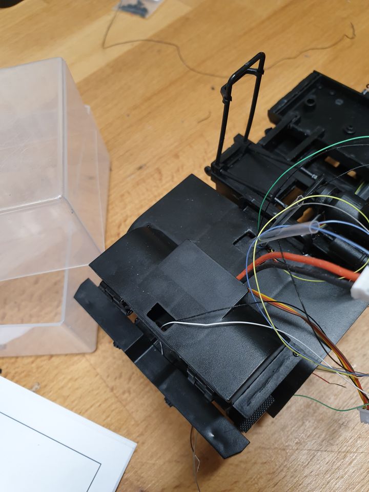
Little steps assembled, bed resprayed, hole cut in cab base to get the wires through (OH didn't think about how to get the wires around the model at all as far as I can tell). Five more LEDs wired (but not enough yellow wire for them, so they're linked with white which will upset me until I can't see it), four left to go.
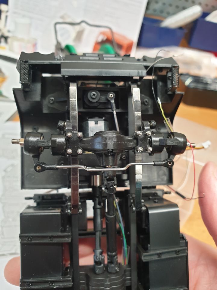
I got the controller and servo and motor wired up. The wheels wouldn't turn at all at first - I think the transfer case was a bit tight - but now spin. But not all in the same direction - I managed to build both back axles the wrong way around. One fixed, one to go.
I got the controller and servo and motor wired up. The wheels wouldn't turn at all at first - I think the transfer case was a bit tight - but now spin. But not all in the same direction - I managed to build both back axles the wrong way around. One fixed, one to go.
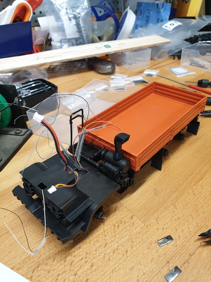
Bed is repainted and mounted, and only fell apart three times because the sides didn't come out of the mould straight.
Got the light covers and grille on the cab. None of the holes for the light covers had been formed properly, and one I cut too big. Similarly the holes for the mirrors are too small.
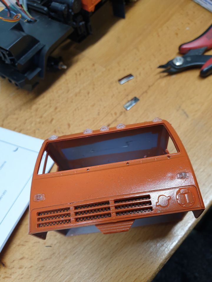
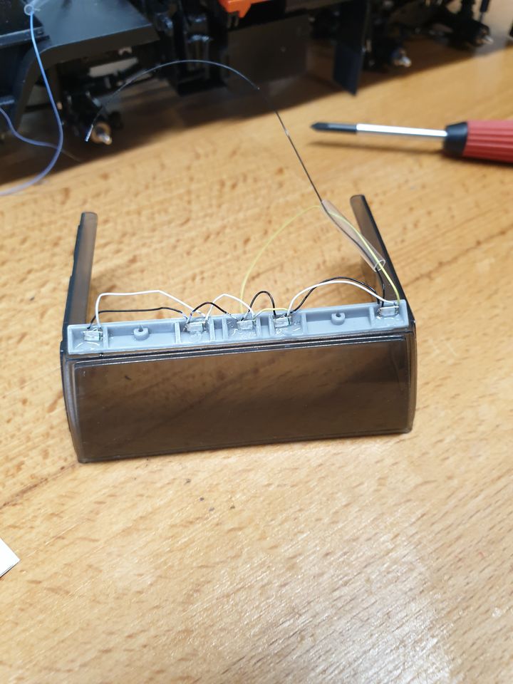
The LEDs for the top bit are supposed to just perch on top of the windscreen, but there's no way they'd stay there while you try to wrestle the windscreen into the cab, so I superglued them in. Obviously there's no channel for the wires from the lights, and unless you file little grooves for them they foul against the inside of the cab.
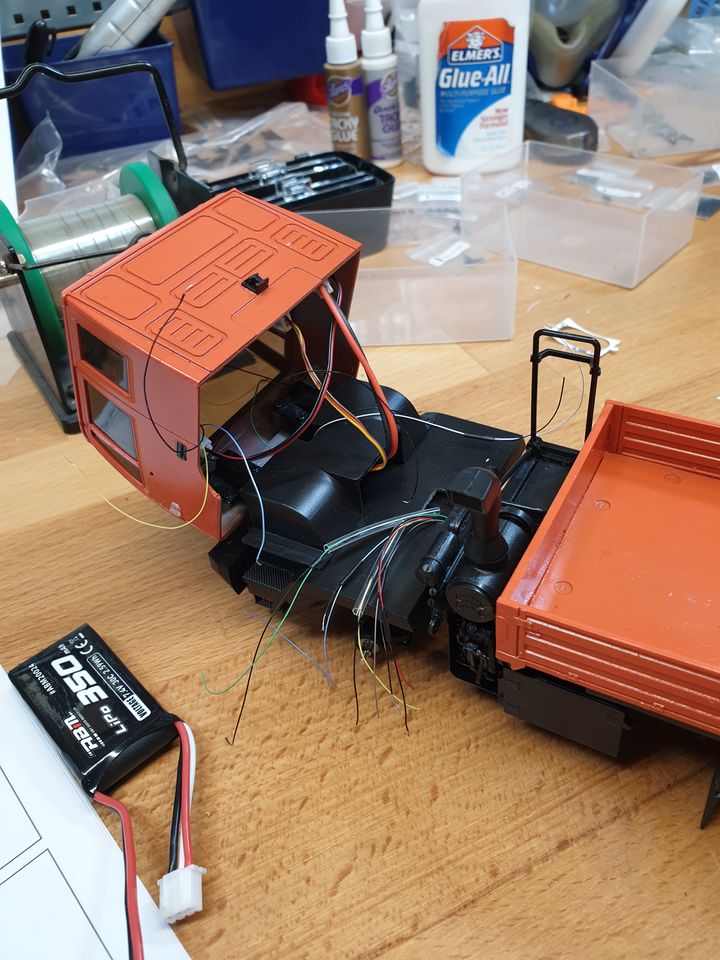
The cab indicators go in little carriers which again have no holes for the wires so are an absolute pig to fit. I didn't take photos of them because they had angered me considerably by this stage. I glued them, left them overnight, and then screwed them in. Next the cab gets mounted to its hinges on little screws - unsurprisingly this is rather awkward as it doesn't tip up enough to get a screwdriver in at all straight.
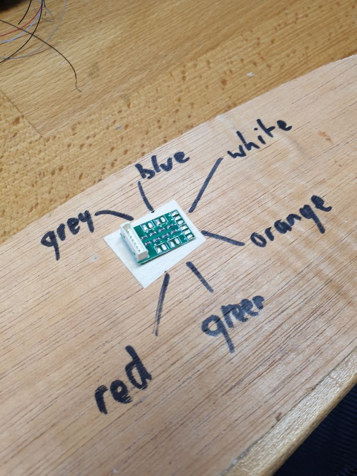
Now time to wire the LEDs to the light breakout board. First I tinned all the pads, and wrote a little key of what goes where:
Next I stuck the board to a little bit of scrap wood using golf grip tape to get it in the right place, and started soldering.
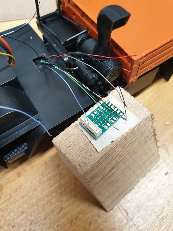
And then a smaller bit of wood to do the indicators on the other side.
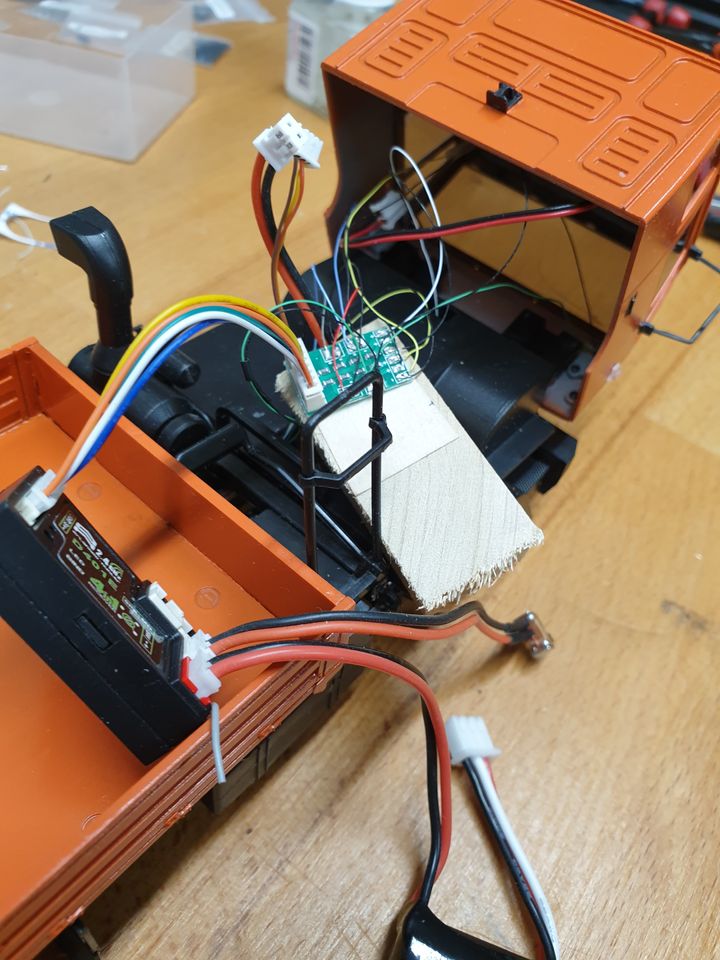
All tested and - quite the surprise - working. I've since stuck the receiver, light board, and speaker to the cab base with more golf grip tape. On the downside I knocked both mirrors off, and one of the horrible little steps. I can't see how I can get the latter back on without taking a lot of things apart, so let's assume it's right hand drive and the passenger can just jump in.
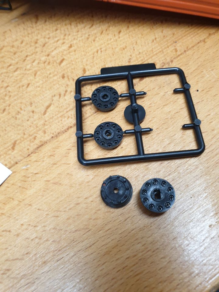
No photos of this bit but I then put 60 little screws into 6 wheel carriers - bizarrely the holes were exactly the right size for the screws to bite into. However, normality was resumed when it turned out the holes on the back are too small for the axles to fit. Each will have to be carefully enlarged with needle files and a scalpel. Really unimpressed with the quality of the moulding and design of this kit.
Got the light covers and grille on the cab. None of the holes for the light covers had been formed properly, and one I cut too big. Similarly the holes for the mirrors are too small.
The LEDs for the top bit are supposed to just perch on top of the windscreen, but there's no way they'd stay there while you try to wrestle the windscreen into the cab, so I superglued them in. Obviously there's no channel for the wires from the lights, and unless you file little grooves for them they foul against the inside of the cab.
The cab indicators go in little carriers which again have no holes for the wires so are an absolute pig to fit. I didn't take photos of them because they had angered me considerably by this stage. I glued them, left them overnight, and then screwed them in. Next the cab gets mounted to its hinges on little screws - unsurprisingly this is rather awkward as it doesn't tip up enough to get a screwdriver in at all straight.
Now time to wire the LEDs to the light breakout board. First I tinned all the pads, and wrote a little key of what goes where:
Next I stuck the board to a little bit of scrap wood using golf grip tape to get it in the right place, and started soldering.
And then a smaller bit of wood to do the indicators on the other side.
All tested and - quite the surprise - working. I've since stuck the receiver, light board, and speaker to the cab base with more golf grip tape. On the downside I knocked both mirrors off, and one of the horrible little steps. I can't see how I can get the latter back on without taking a lot of things apart, so let's assume it's right hand drive and the passenger can just jump in.
No photos of this bit but I then put 60 little screws into 6 wheel carriers - bizarrely the holes were exactly the right size for the screws to bite into. However, normality was resumed when it turned out the holes on the back are too small for the axles to fit. Each will have to be carefully enlarged with needle files and a scalpel. Really unimpressed with the quality of the moulding and design of this kit.
Did it - I butchered them with a scalpel. Compare with the spares on the sprue for how much material needs to be removed to get them to fit.
Then just 60 tiny nuts to get the wheels fixed in place, and it's done (bar putting the wing mirrors on again). Didn't run very happily to begin with but I loosened the screws on the transfer box a little and it opened up and trundles around nicely. I've managed to break the wire to the cab-top lights but I'm not that fussed about them - I'll likely redo it at some point, but for now I'm just relieved to be finished.
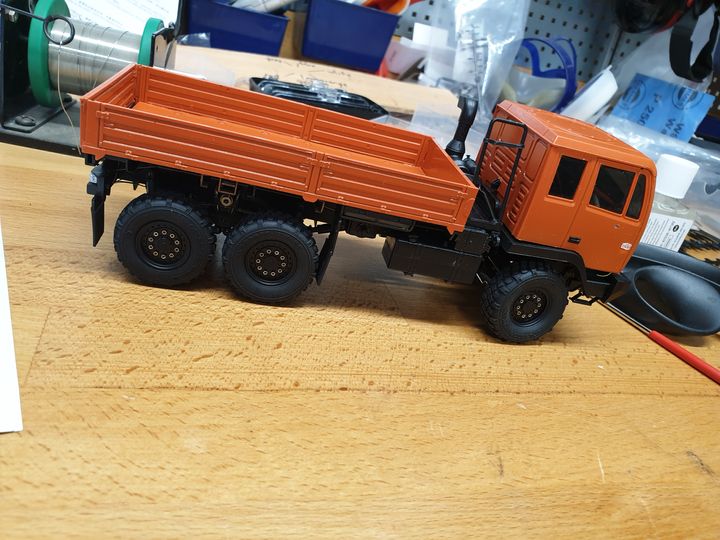
Then just 60 tiny nuts to get the wheels fixed in place, and it's done (bar putting the wing mirrors on again). Didn't run very happily to begin with but I loosened the screws on the transfer box a little and it opened up and trundles around nicely. I've managed to break the wire to the cab-top lights but I'm not that fussed about them - I'll likely redo it at some point, but for now I'm just relieved to be finished.
Gassing Station | Scale Models | Top of Page | What's New | My Stuff


