Caterham Superlight - Custom Tamiya 1/12
Discussion
After finally waving goodbye to my 2xR500 models that I have been carrying around the world for 17 years, I'm on to my next Caterham model - also 'ordered' back in 2002. I have very patient friends! But I'm on a role now, so hopefully this one should only be about 9 years....
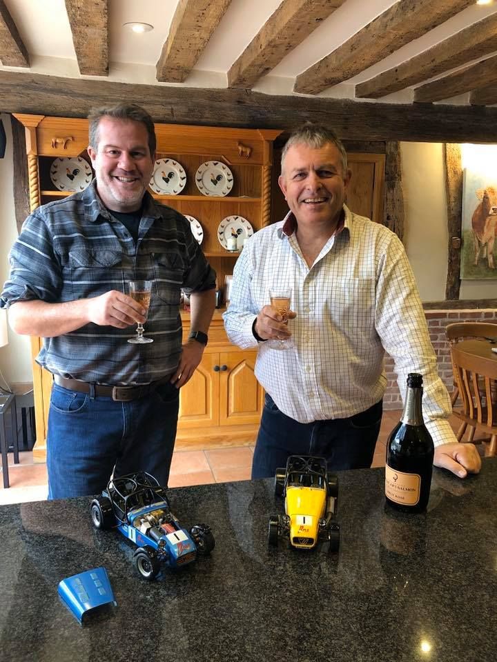
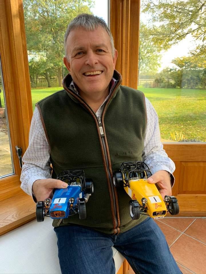
This will be a model of a K-series Superlight - so no cage or decals (thanks god) but the same level of detail - in fact probably more after 17 years 'experience'...
Here are a few shots of the 'real' car:
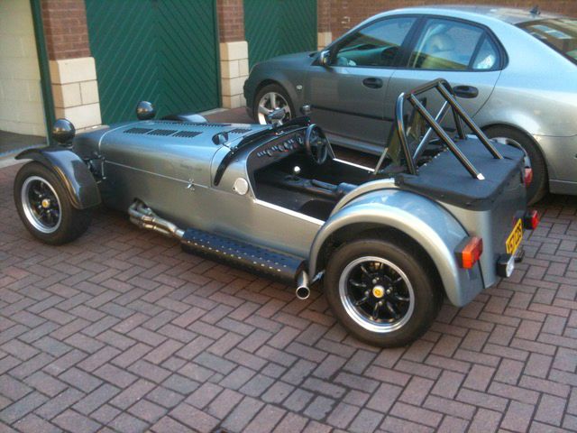
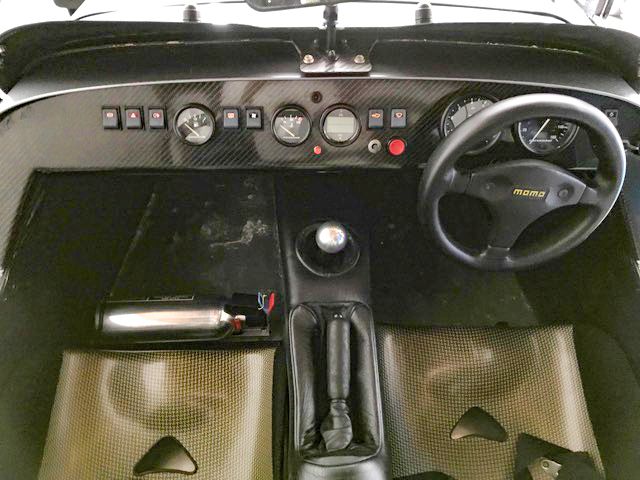
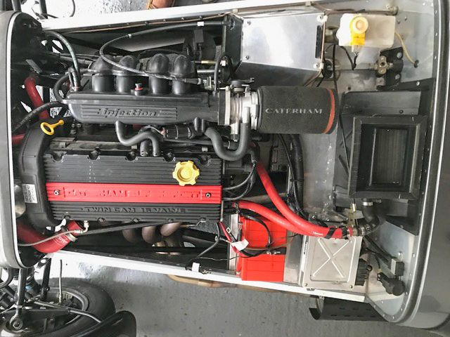
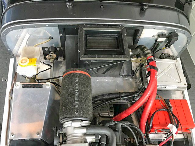
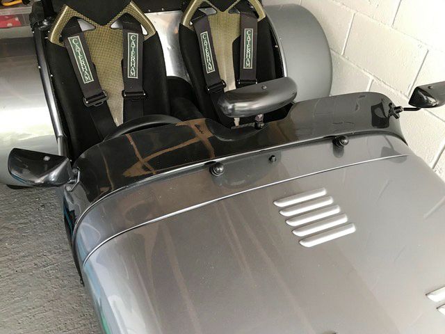
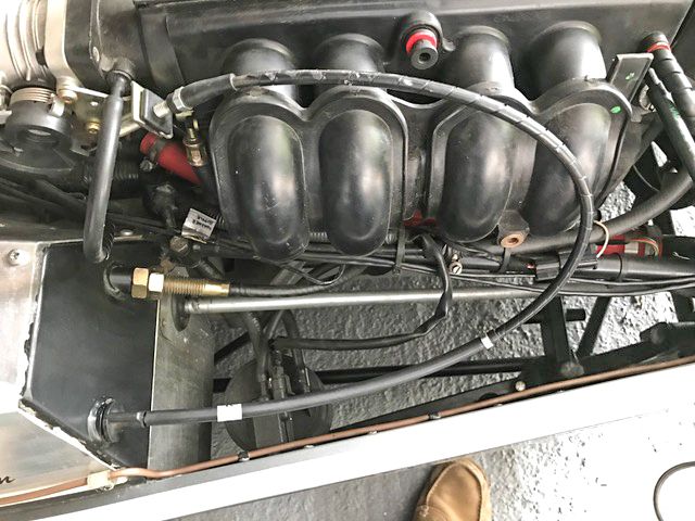
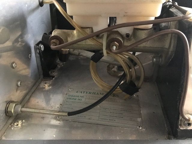
But in this model I have already made extensive use of my new 3D printer. I have pushed myself with Solidworks, and drawn up the k-series engine entirely - every part drawn up and printed. Have also made a start on ancillaries like ECU etc.
This first load of pictures will be a big dump, as I started a month ago but did not do the sensible thing and start the build diary as I went - so this is the catch up...
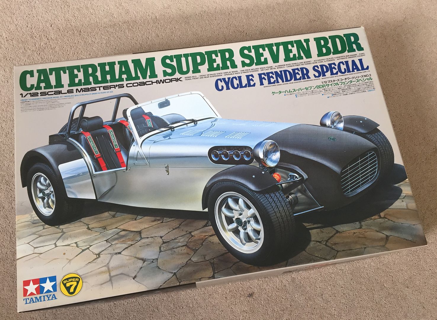
This version of the kit is getting harder to find - it has not been re-issued by Tamiya. I got this one in 2002!
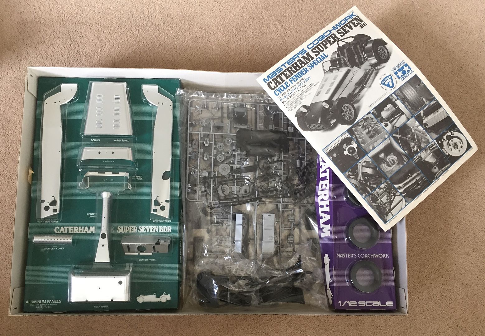
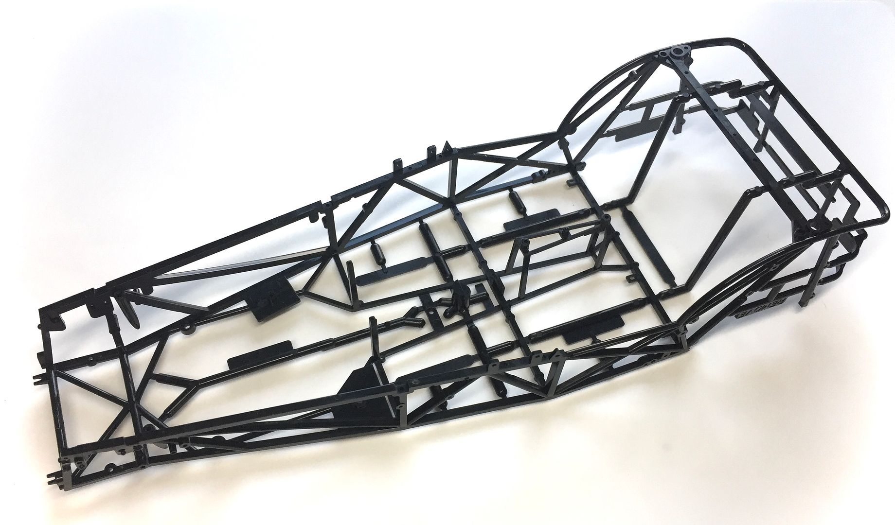
I actually end up using less and less of these kits with these builds - but nothing replicates the chassis or ali bodywork, which is superb.
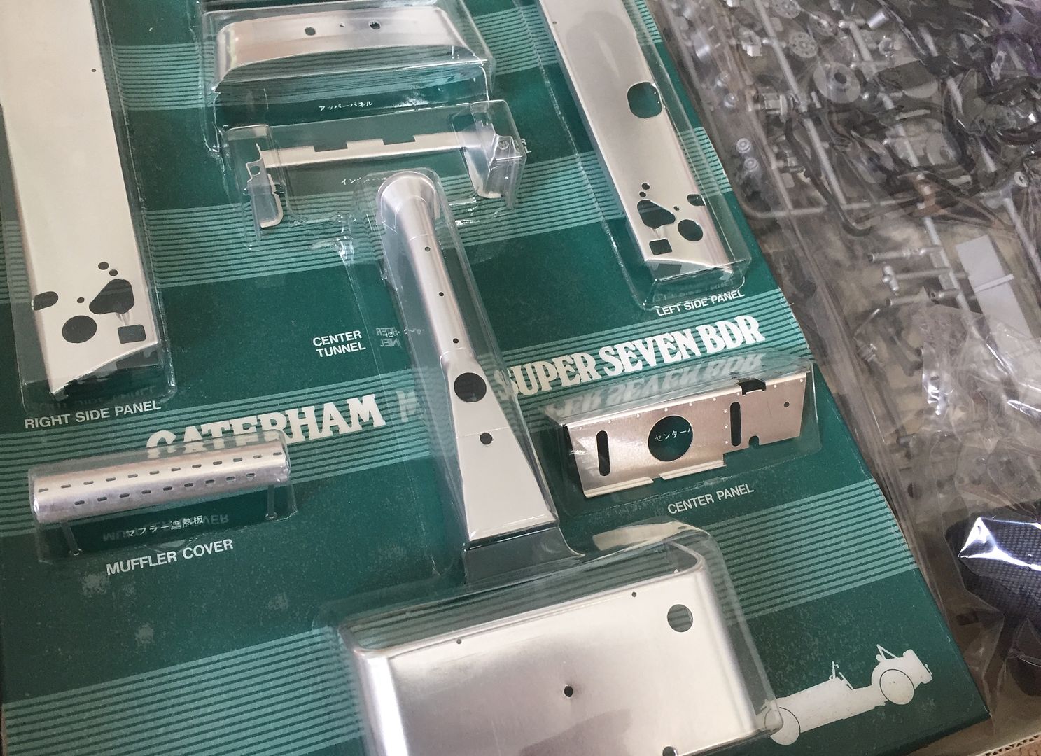
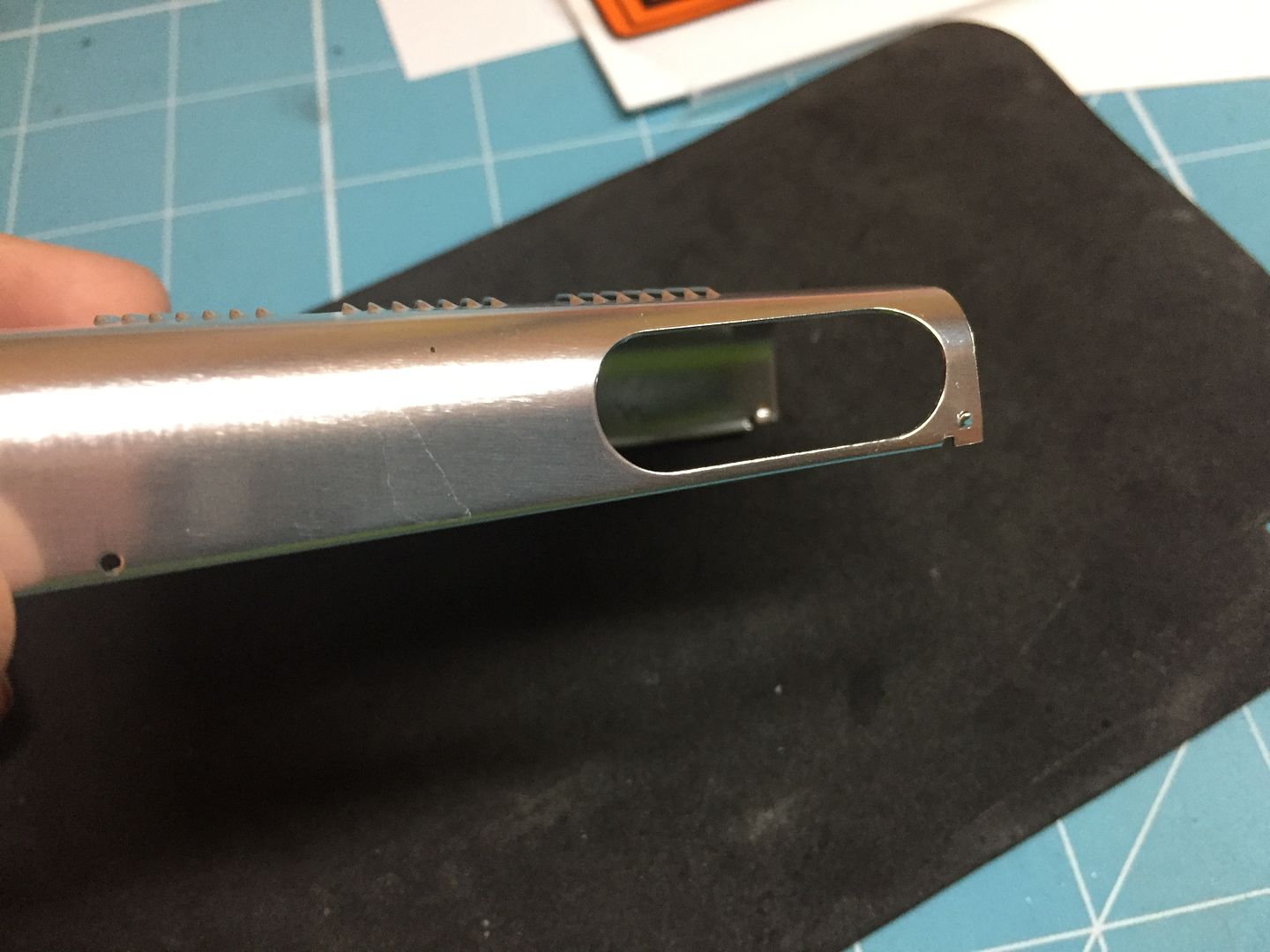
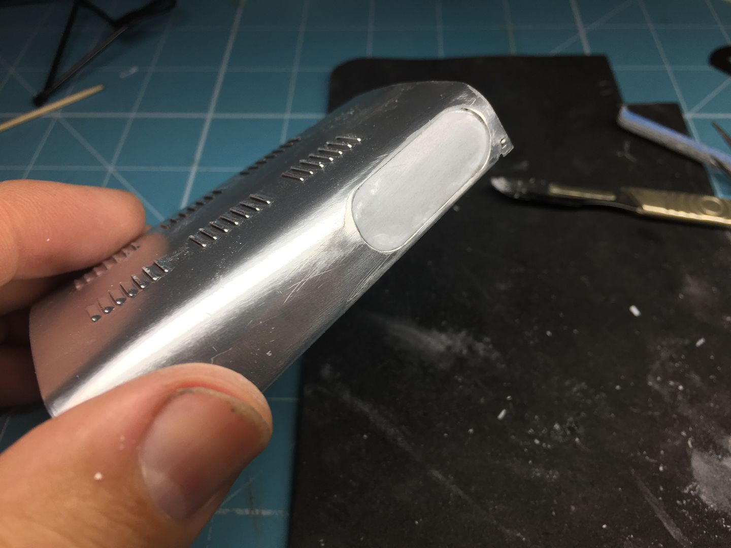
Because the engine is different from the BDR in the kit, I have to block off the hole in the bonnet that is for the old-style carbs. Also have to fill the spare wheel carrier bolt hole on this particular car.
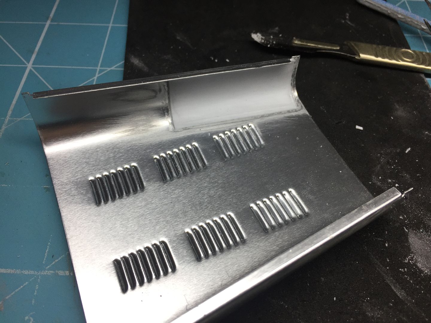
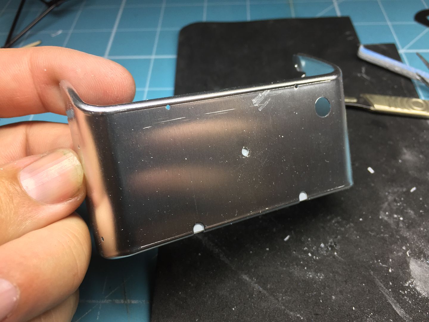
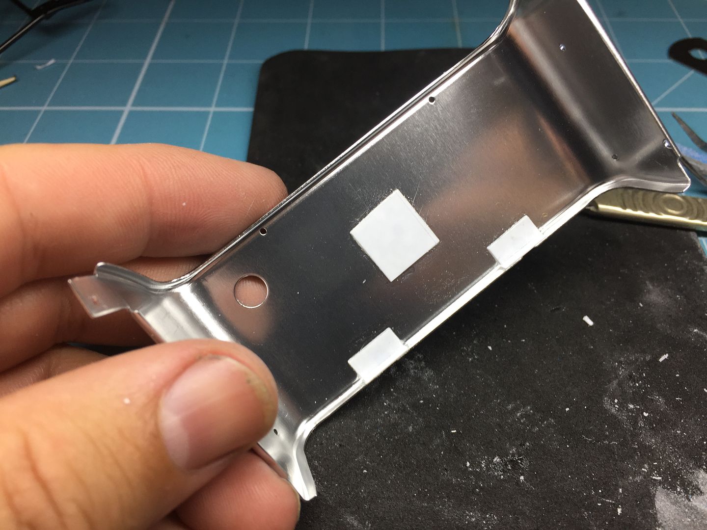
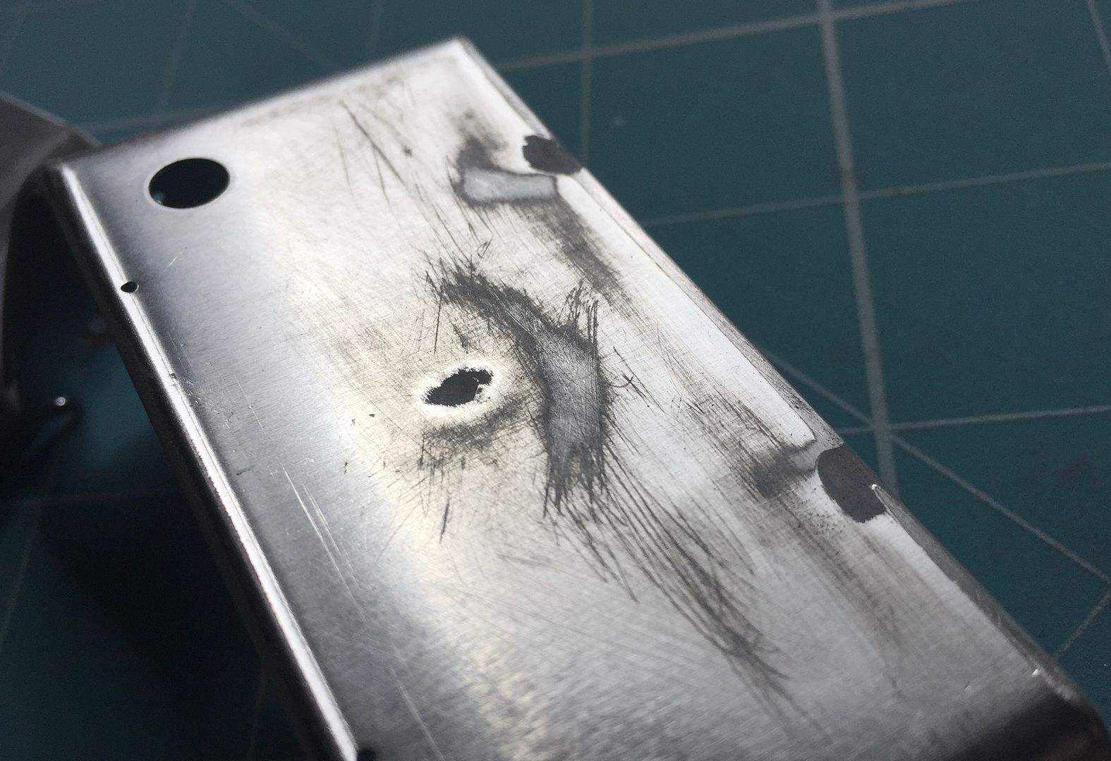
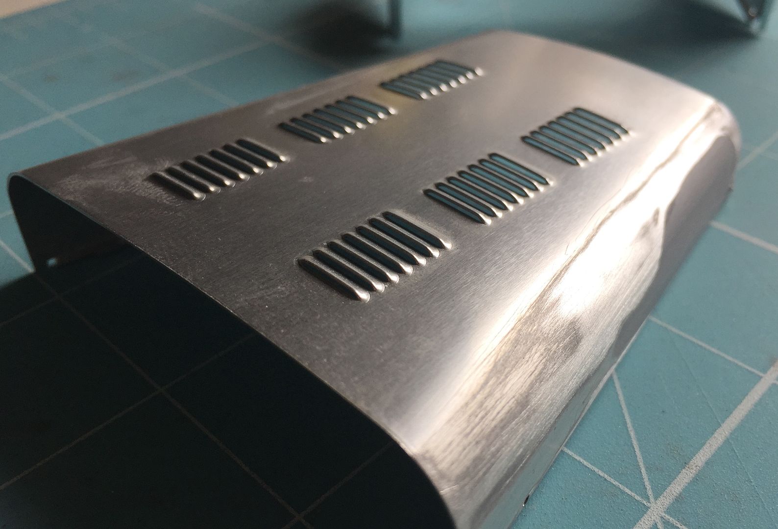
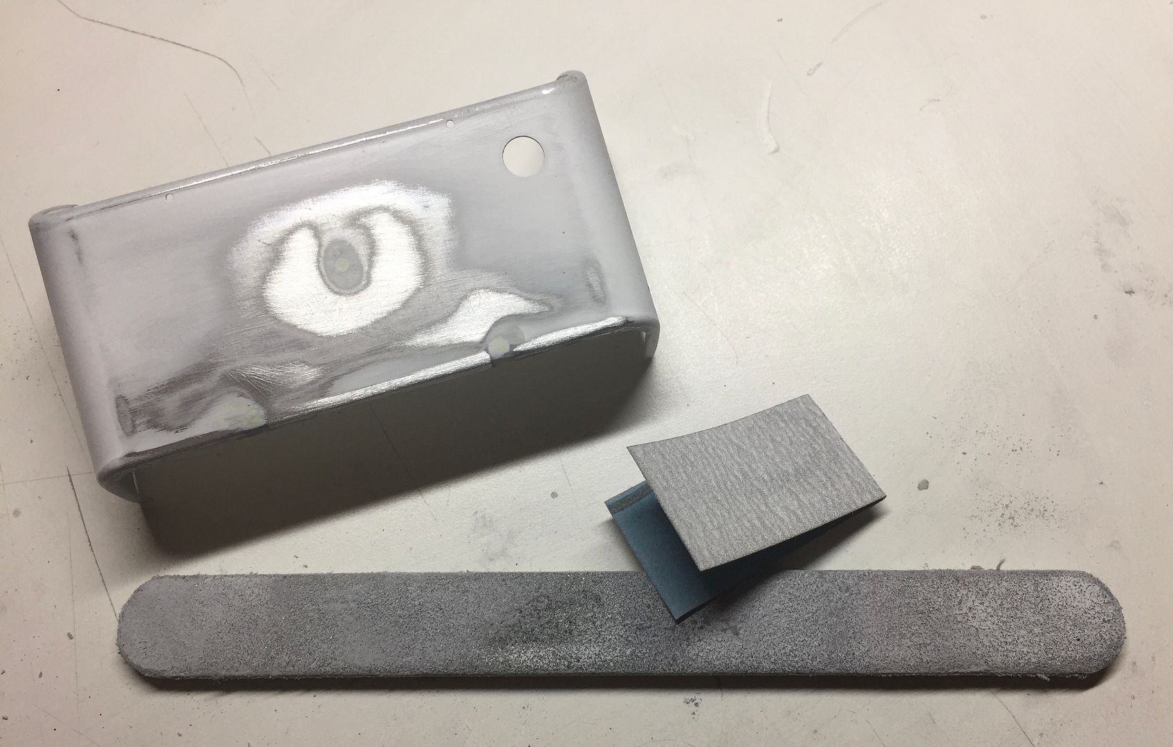
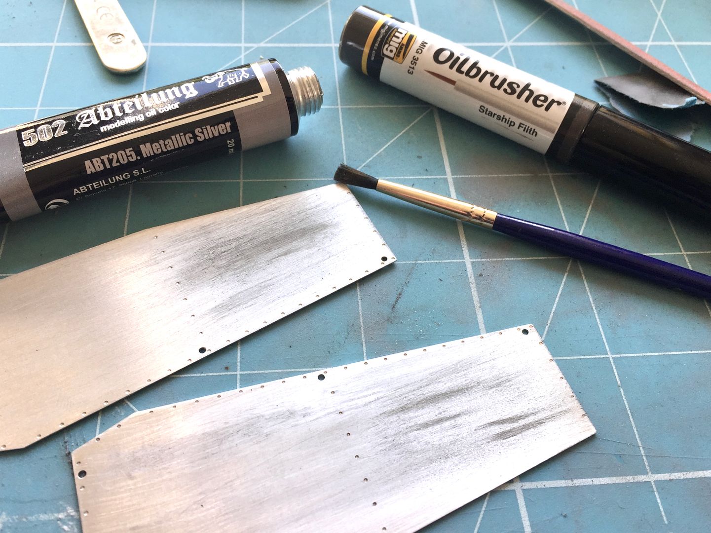
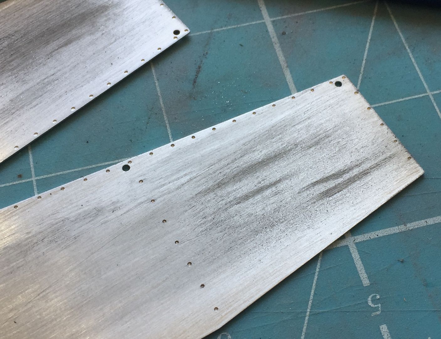
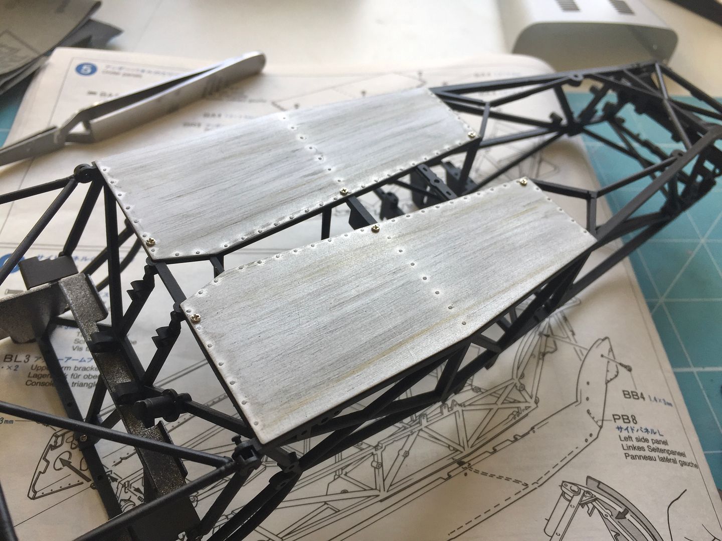
I fitted the interior/floor ali panels - I'm not 'weathering' the car as such, but added some wear and tear to reduce the shiny ali look.
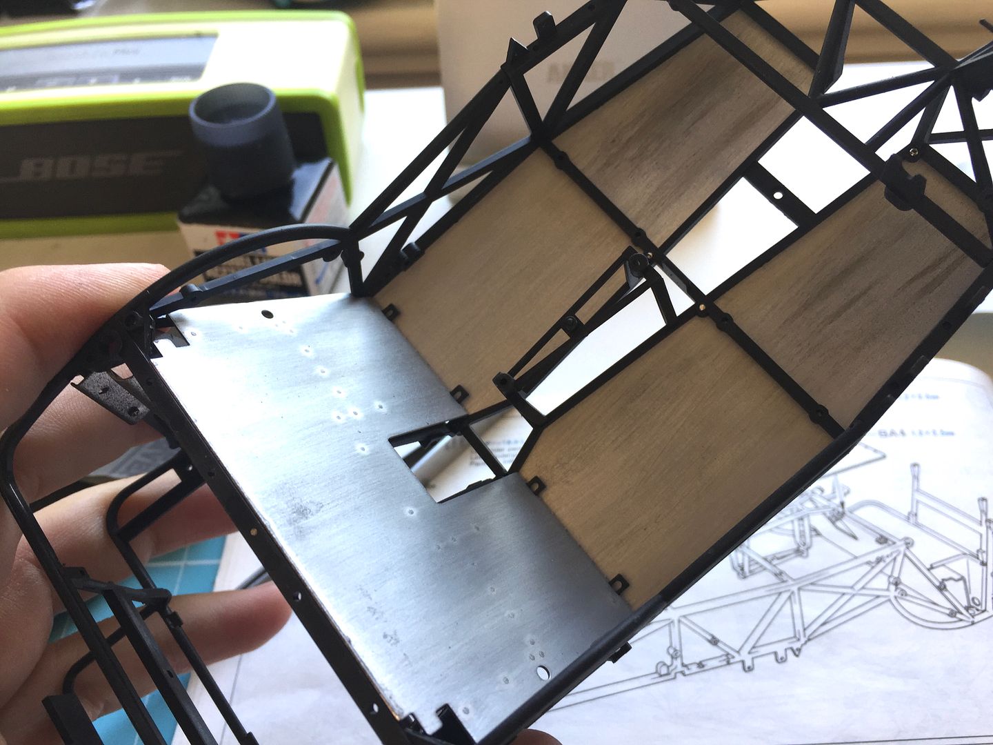
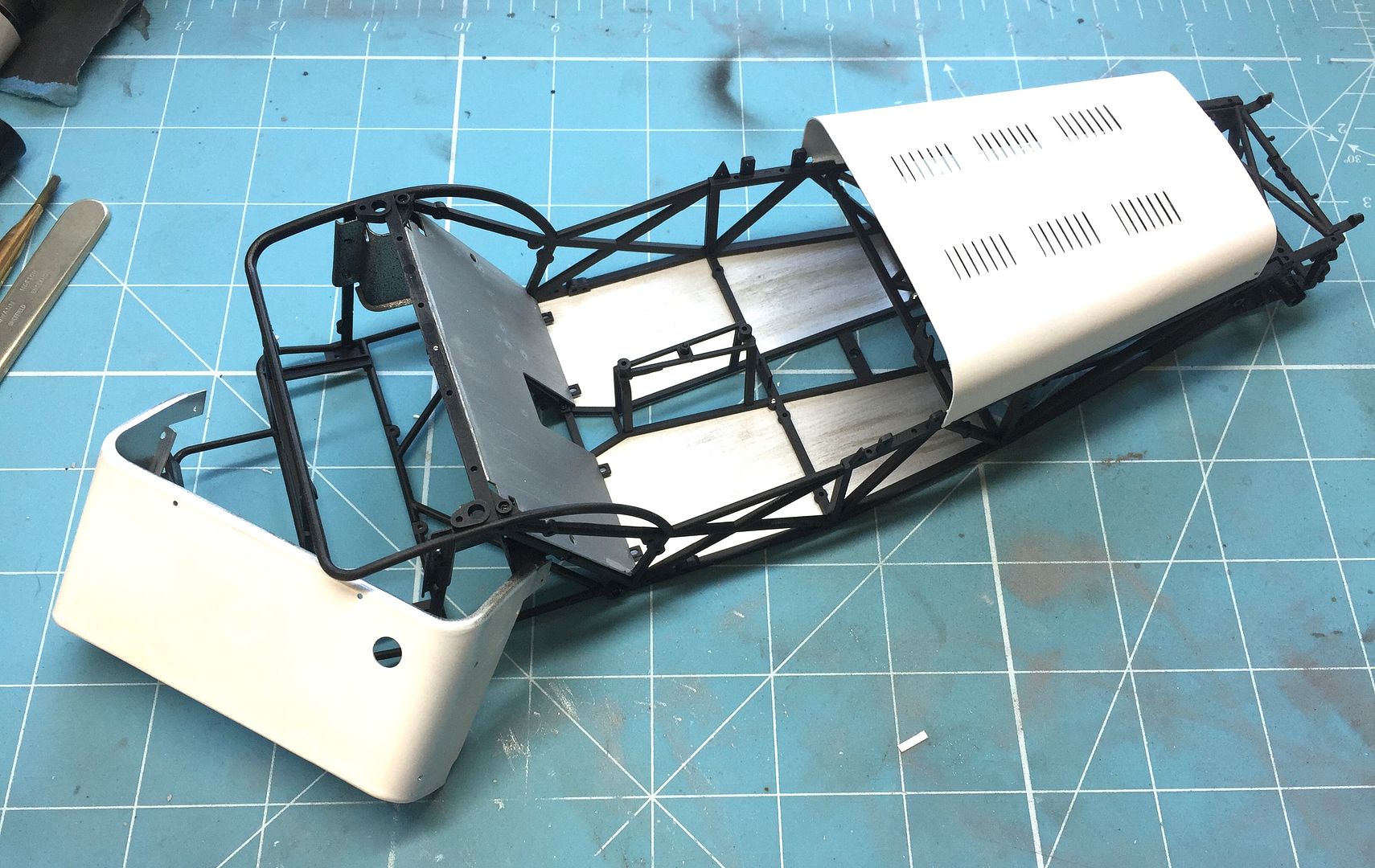
The Tamiya kit comes with an old style heater (about 3 models back I think!) and this model has a newer version - I had to make a new bulkhead surface to cover the larger holes on the kit version.
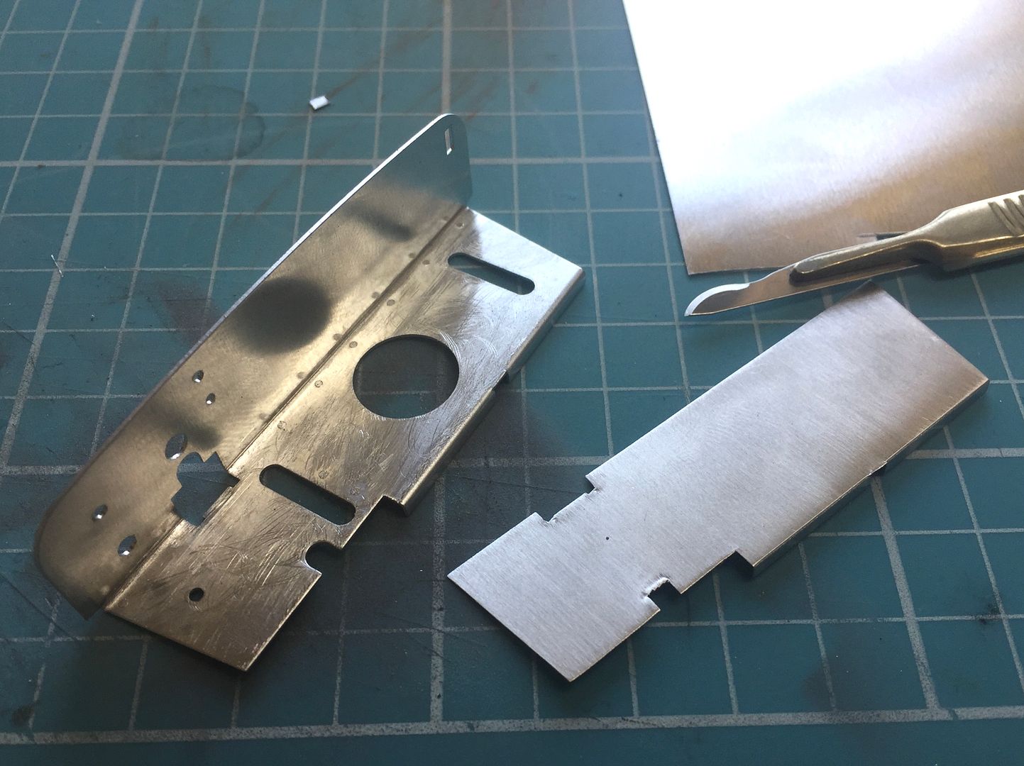
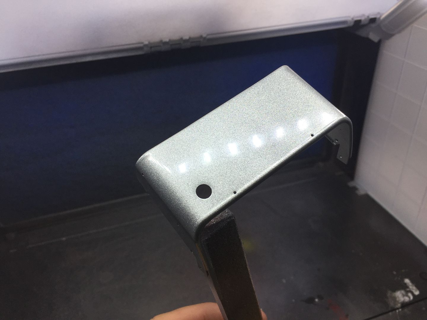
I had started the engine at this point, but once the owner sent me his touch-up paint pot, I primed and sprayed the other aluminium panels, rear wings and nose. The paint is a Ferrari metallic grey, so also needed a clear coat.
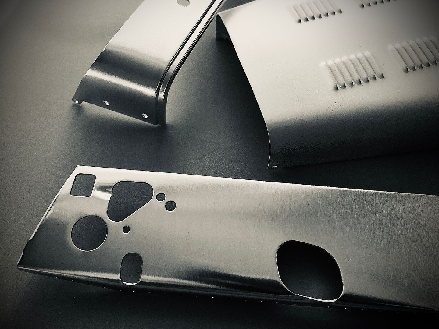
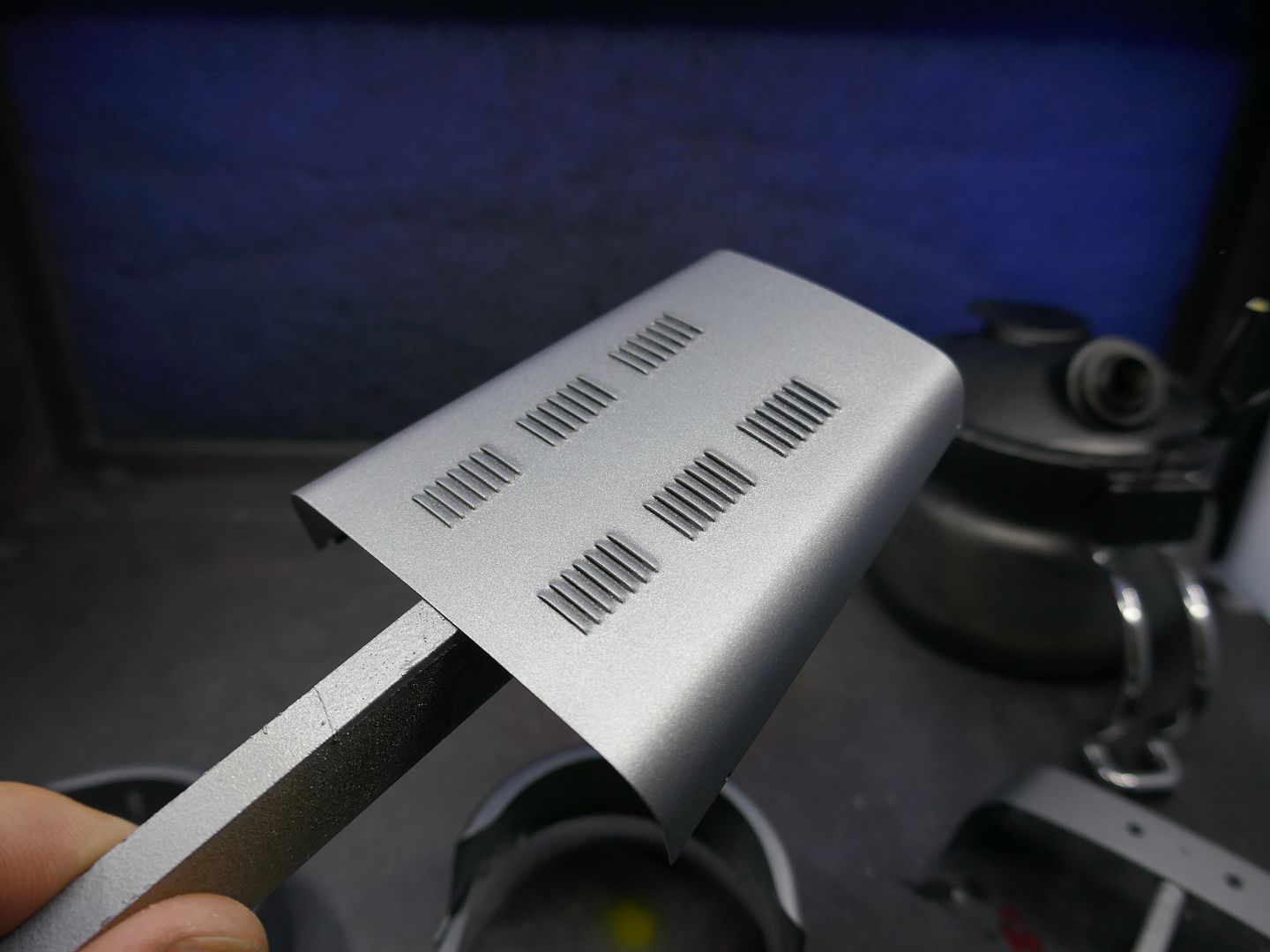
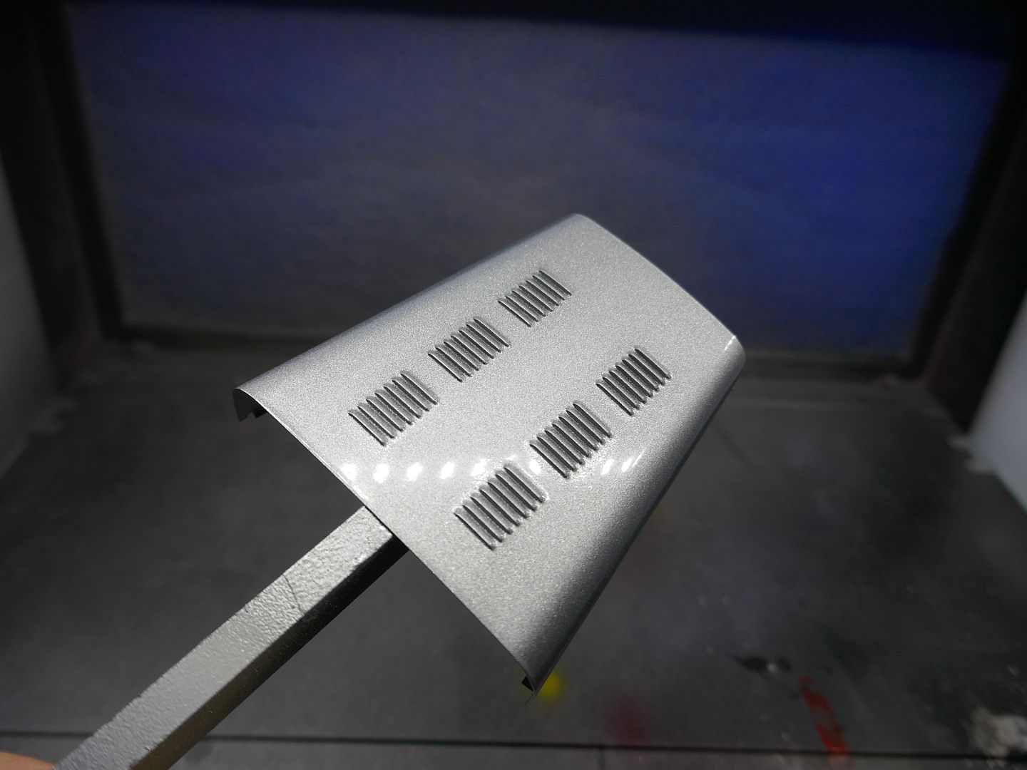
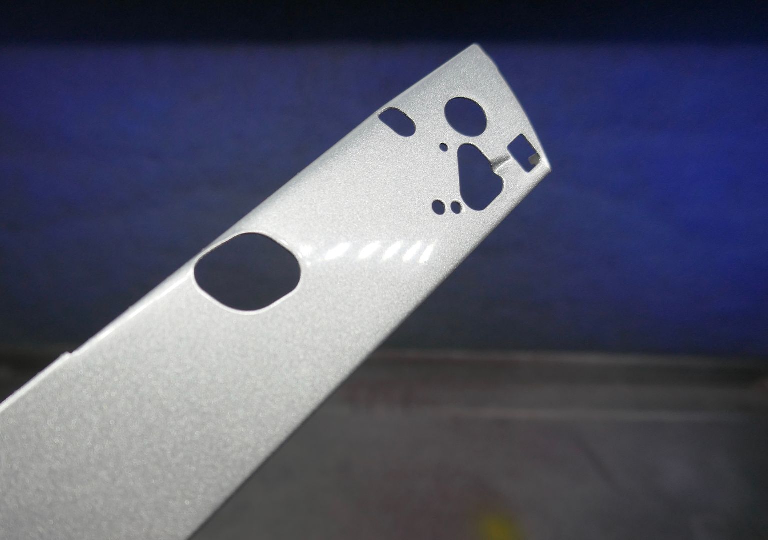
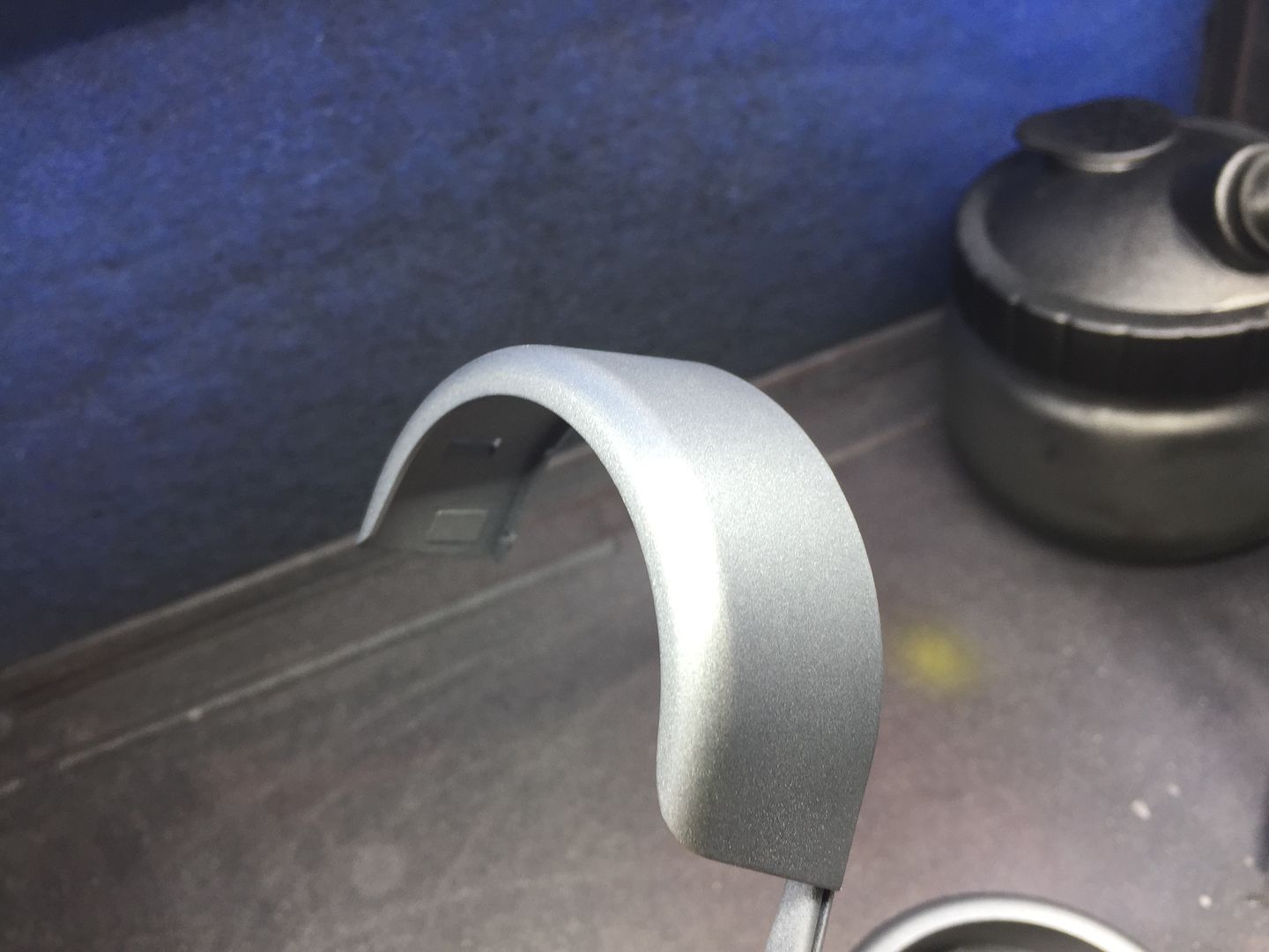
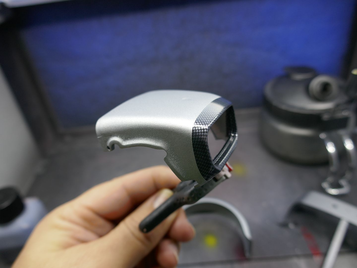
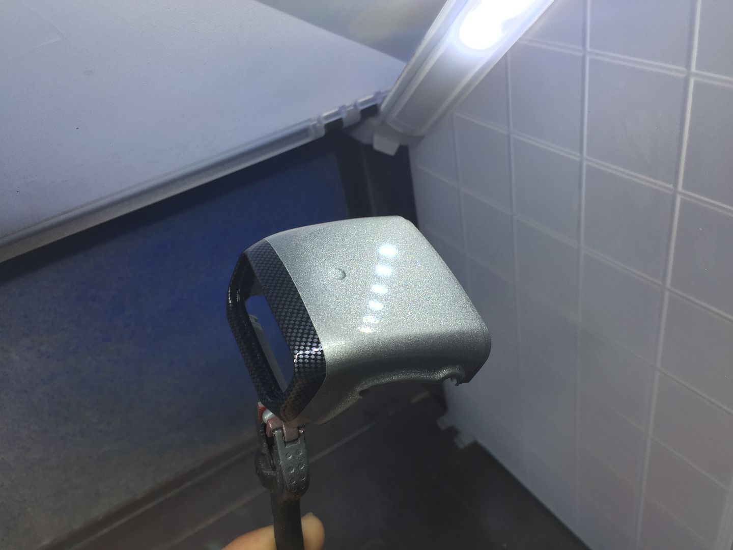
On this kit, the wings and nose are 'carbon fibre' and these parts come with a 'carbon effect' pattern. It is a little crude, but I am going to keep it for the nose strip and the front wings - I shall 'dull it down' a bit with some Tamiya Smoke paint.


This will be a model of a K-series Superlight - so no cage or decals (thanks god) but the same level of detail - in fact probably more after 17 years 'experience'...
Here are a few shots of the 'real' car:


But in this model I have already made extensive use of my new 3D printer. I have pushed myself with Solidworks, and drawn up the k-series engine entirely - every part drawn up and printed. Have also made a start on ancillaries like ECU etc.
This first load of pictures will be a big dump, as I started a month ago but did not do the sensible thing and start the build diary as I went - so this is the catch up...

This version of the kit is getting harder to find - it has not been re-issued by Tamiya. I got this one in 2002!

I actually end up using less and less of these kits with these builds - but nothing replicates the chassis or ali bodywork, which is superb.


Because the engine is different from the BDR in the kit, I have to block off the hole in the bonnet that is for the old-style carbs. Also have to fill the spare wheel carrier bolt hole on this particular car.


I fitted the interior/floor ali panels - I'm not 'weathering' the car as such, but added some wear and tear to reduce the shiny ali look.


The Tamiya kit comes with an old style heater (about 3 models back I think!) and this model has a newer version - I had to make a new bulkhead surface to cover the larger holes on the kit version.

I had started the engine at this point, but once the owner sent me his touch-up paint pot, I primed and sprayed the other aluminium panels, rear wings and nose. The paint is a Ferrari metallic grey, so also needed a clear coat.


On this kit, the wings and nose are 'carbon fibre' and these parts come with a 'carbon effect' pattern. It is a little crude, but I am going to keep it for the nose strip and the front wings - I shall 'dull it down' a bit with some Tamiya Smoke paint.

Edited by caterhamnut on Monday 28th October 21:41
Edited by caterhamnut on Monday 28th October 21:54
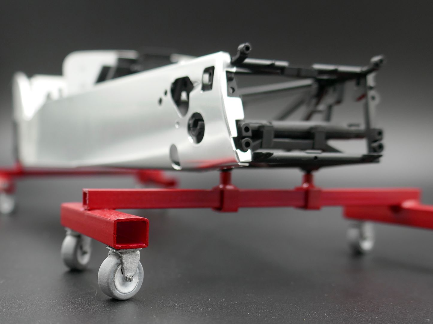
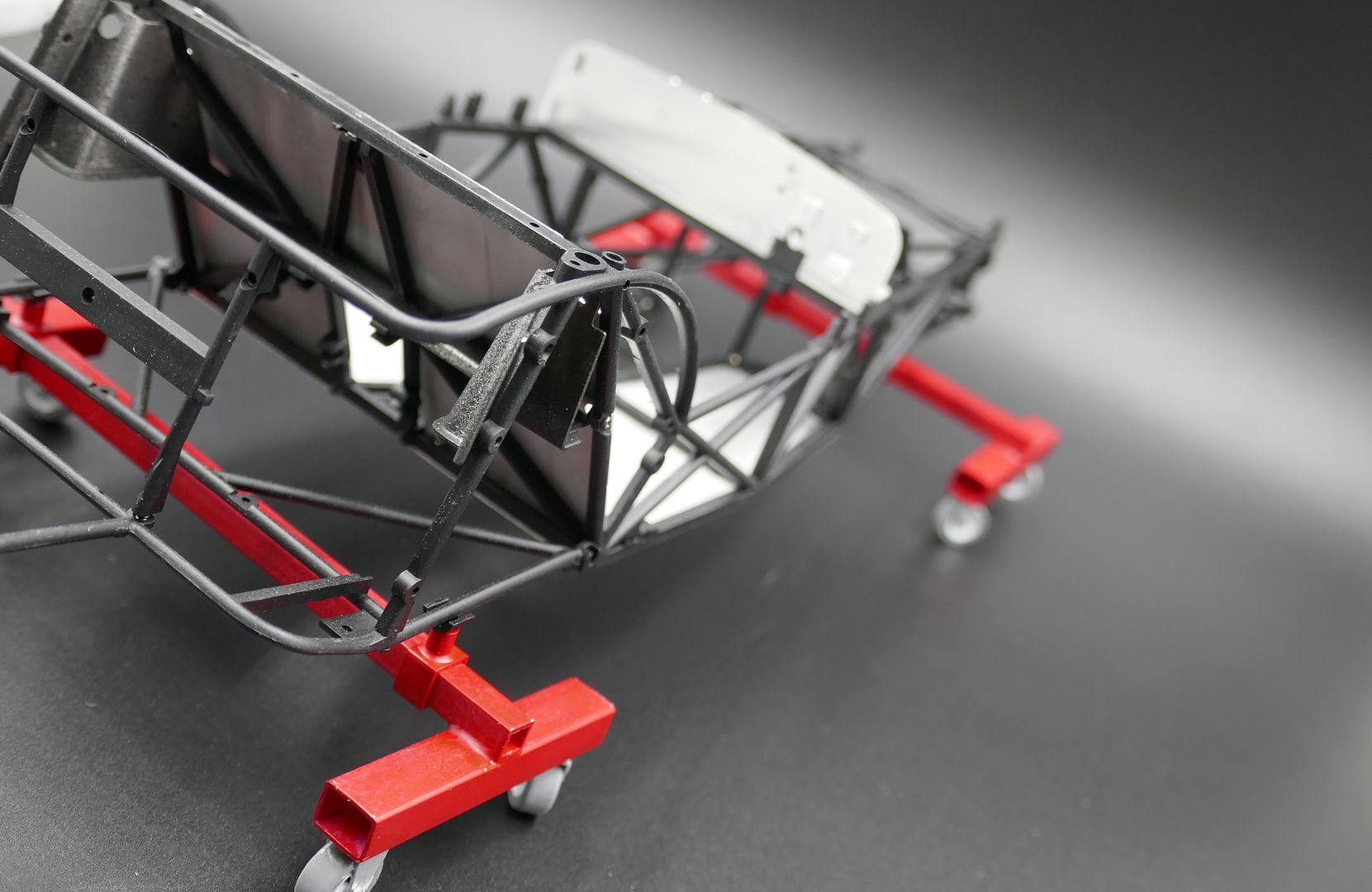
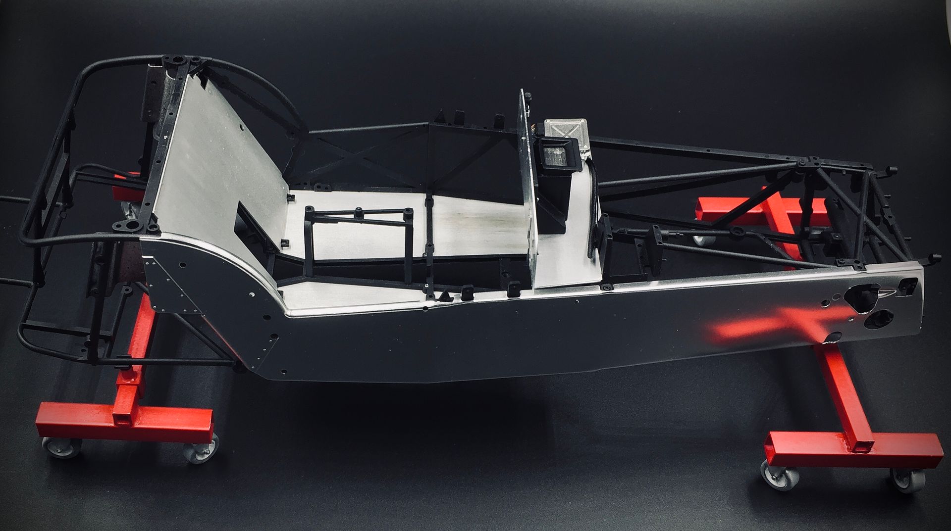
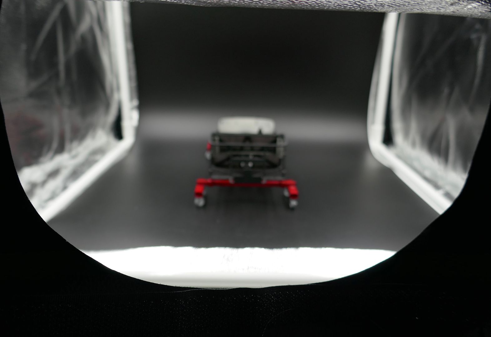
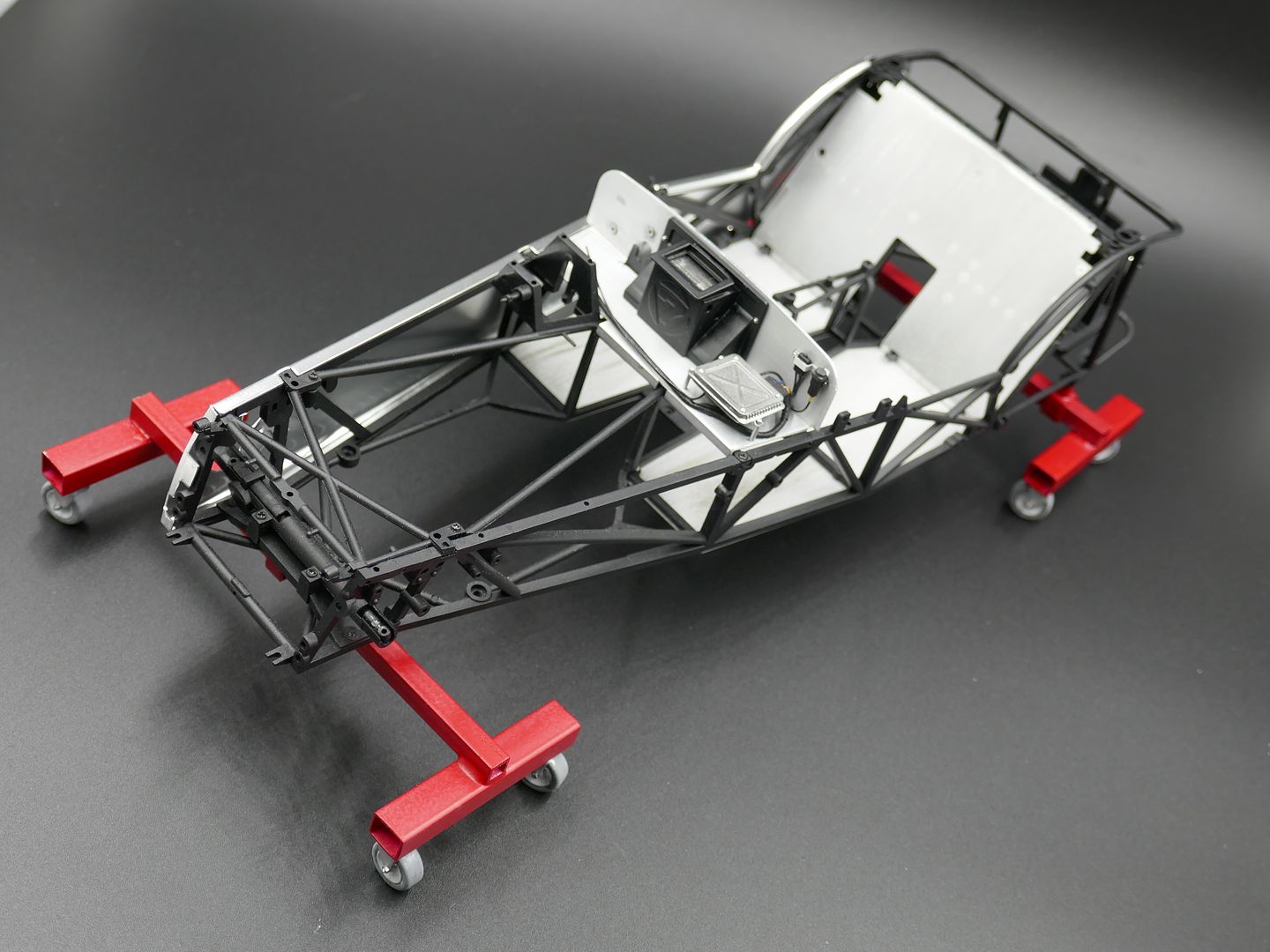
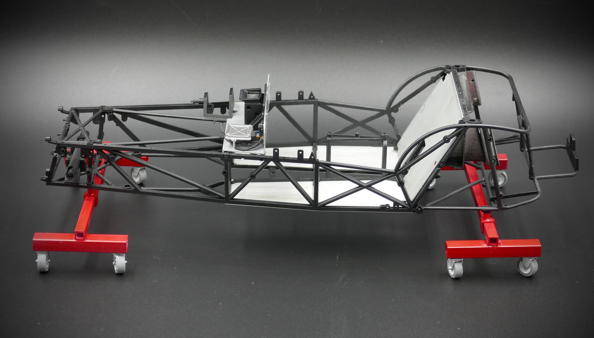
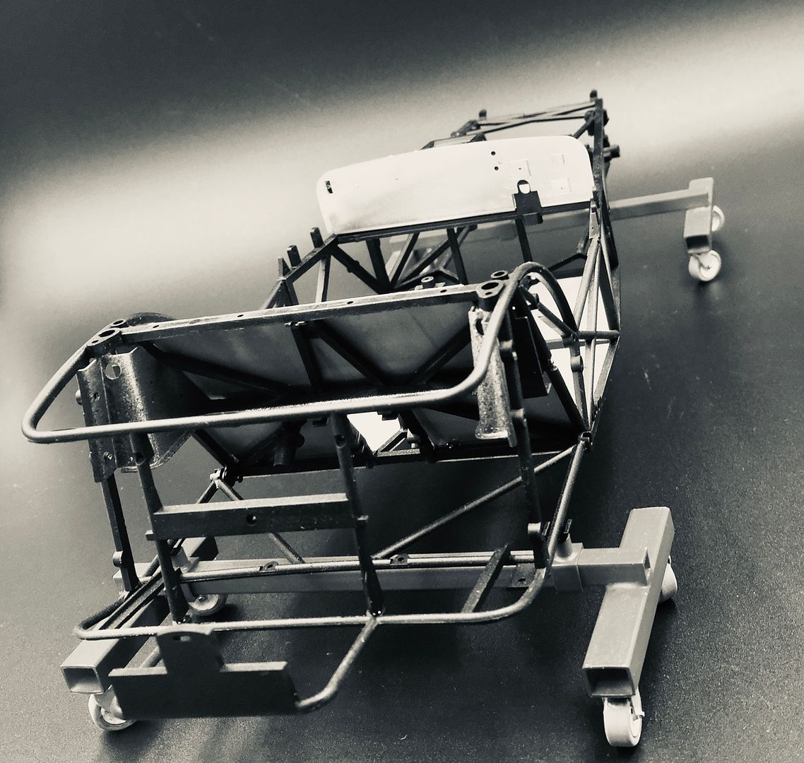
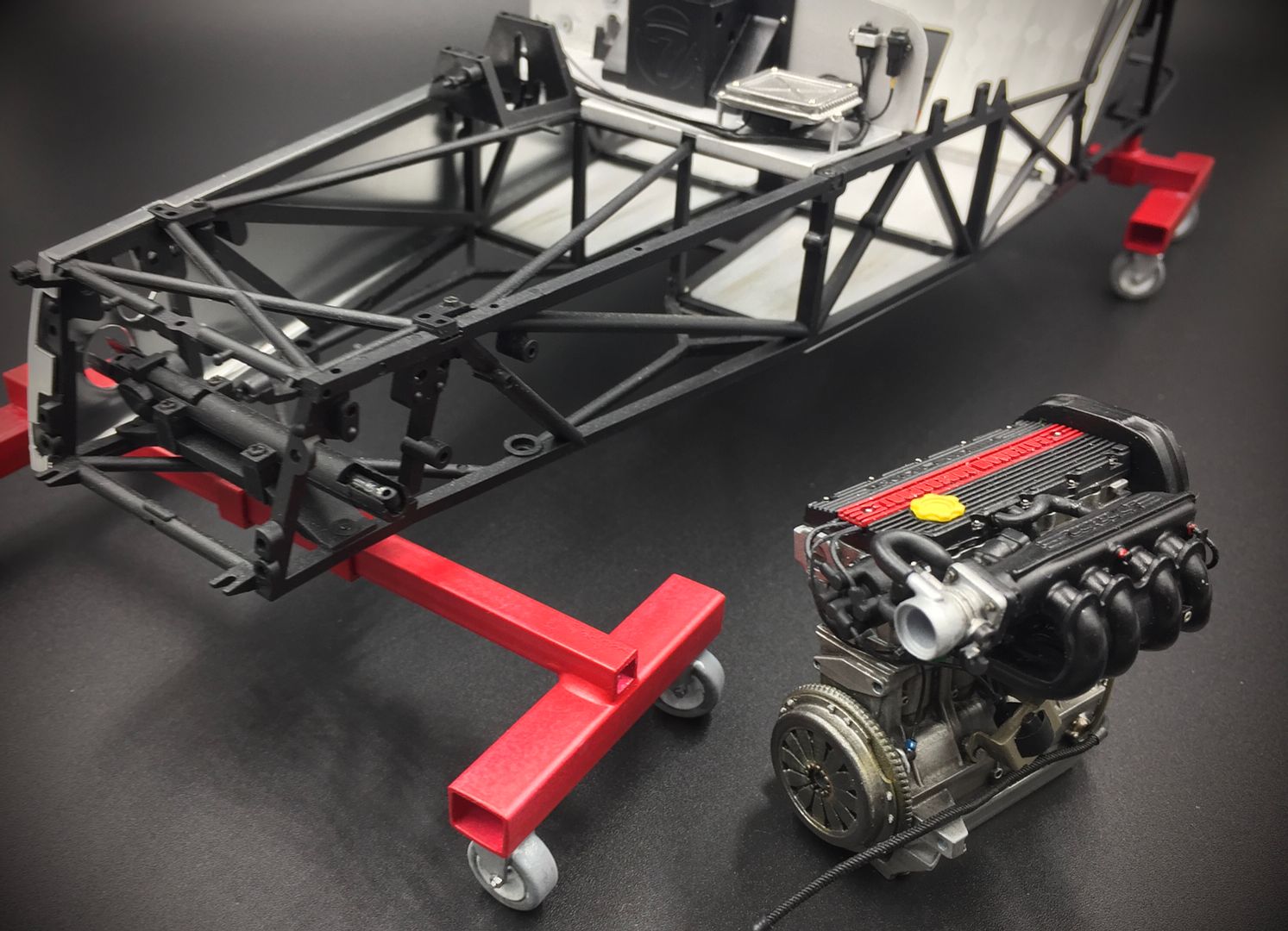
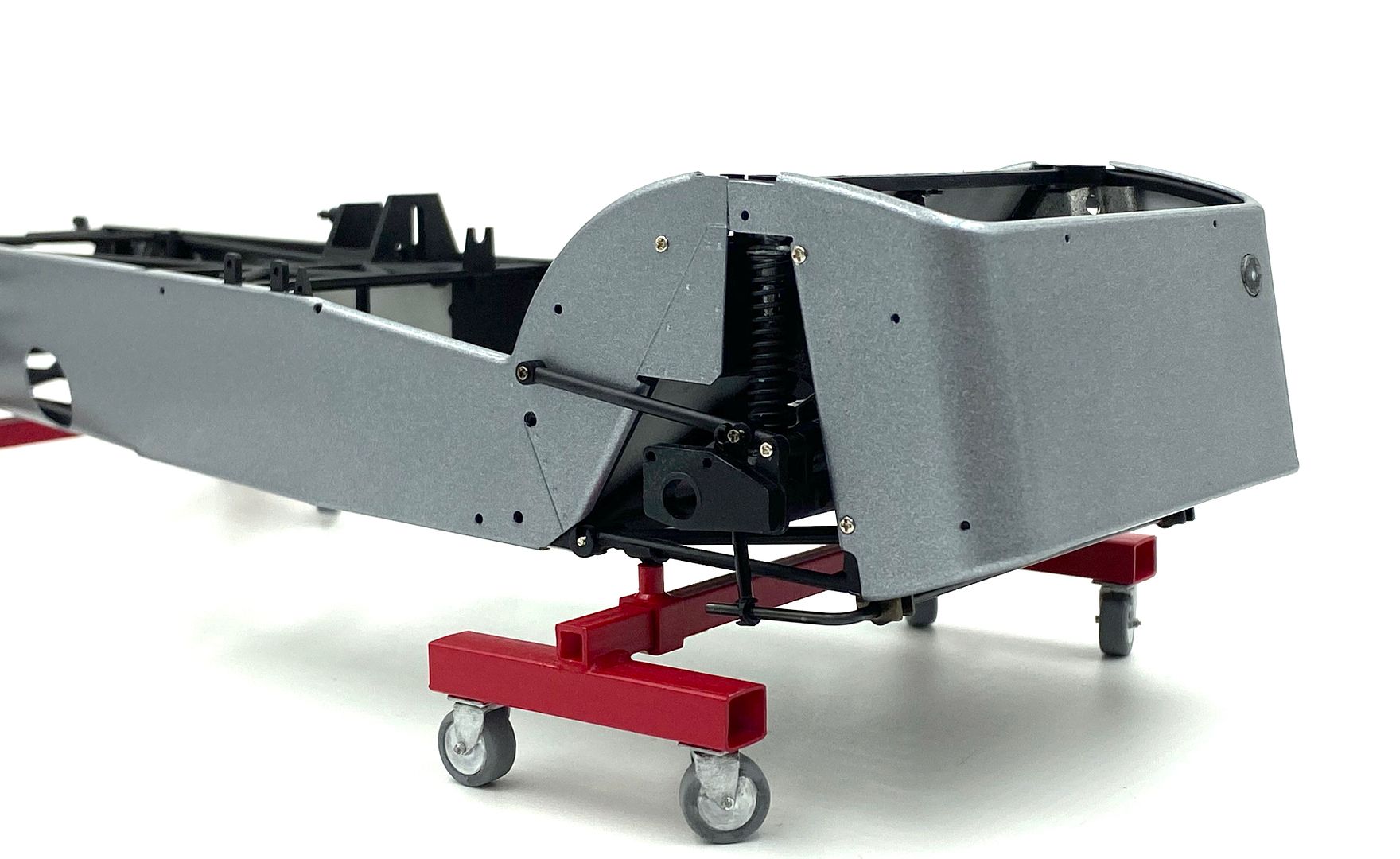
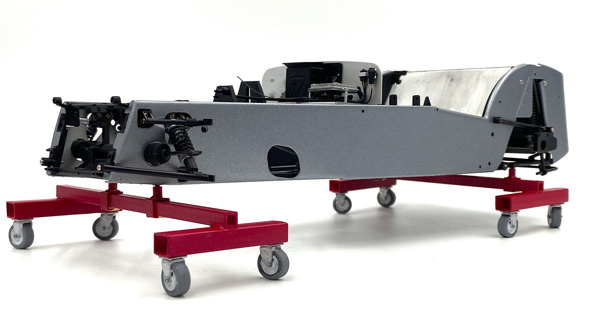
At this point I decided to copy many people who make little pieces of workshop to compliment their photos - and made some chassis trolleys based on the ones we used for our real chassis!
Simple plastic tube and I drew up and 3D printed some castors.
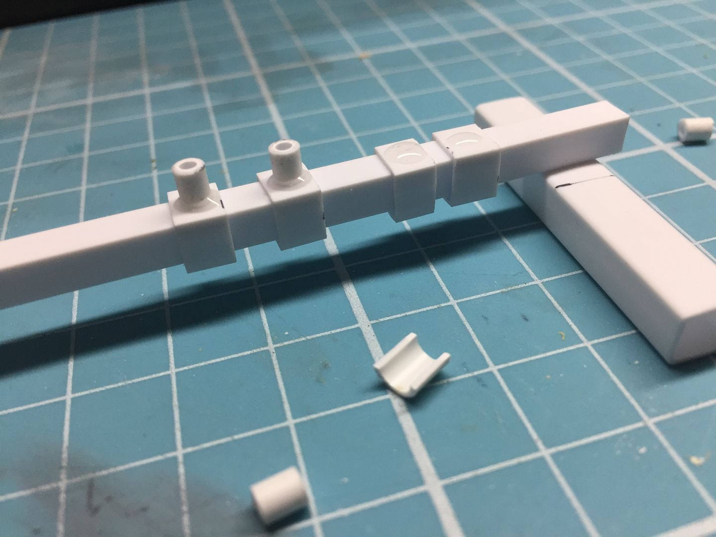
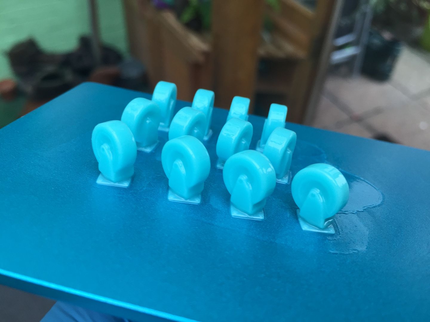
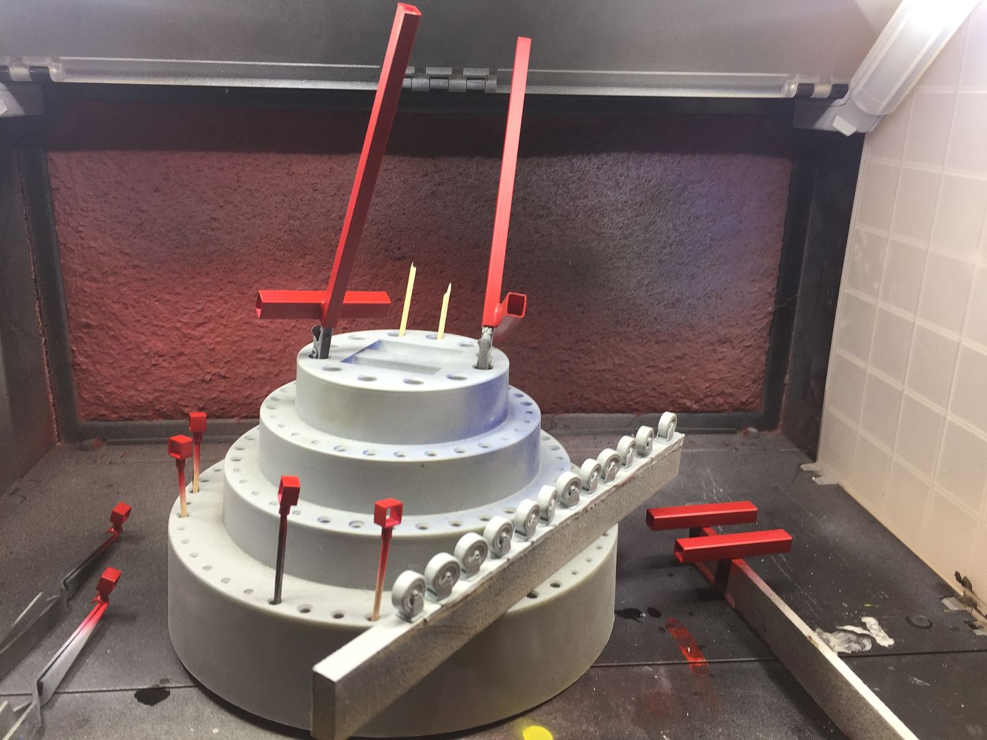
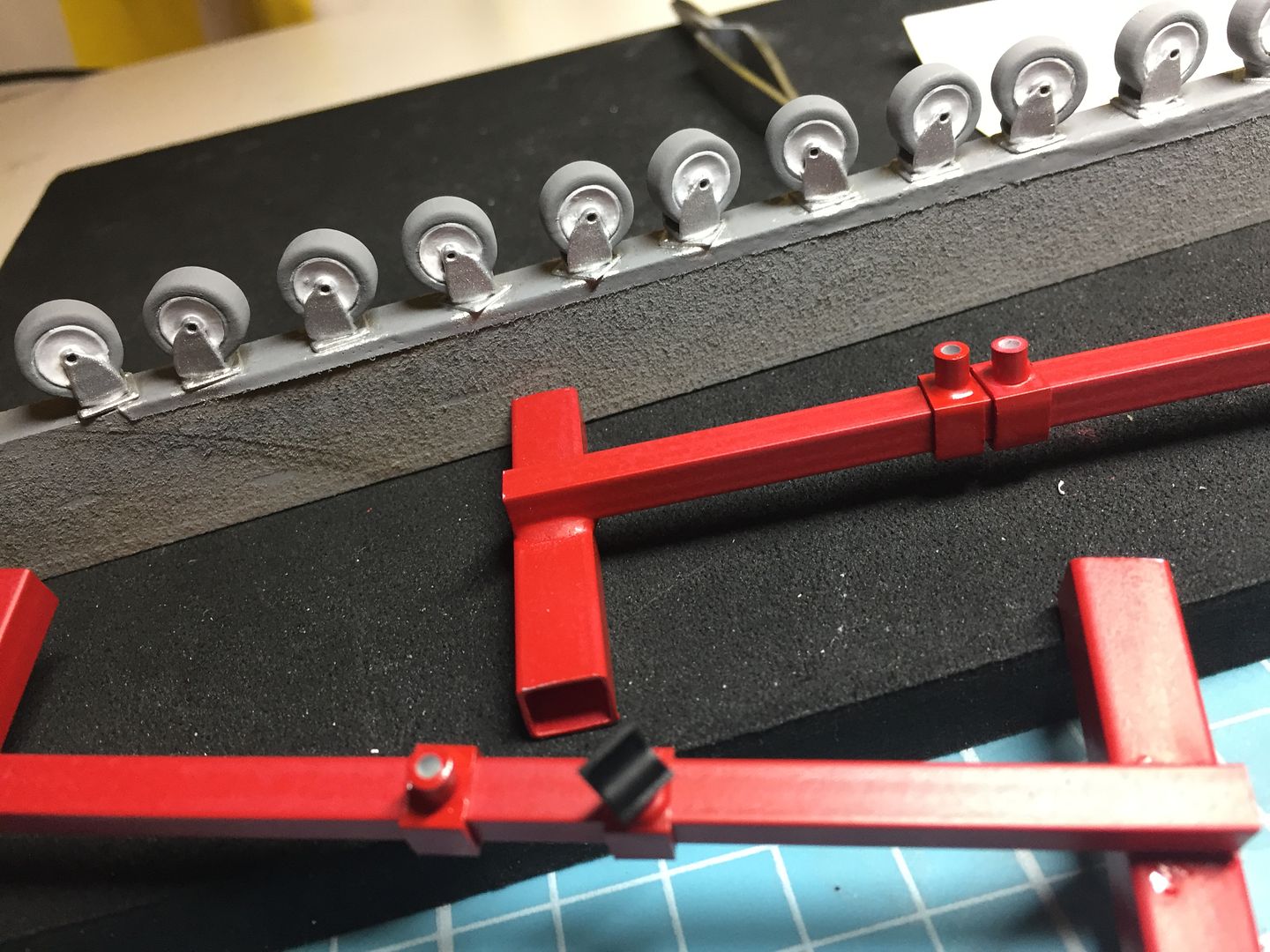
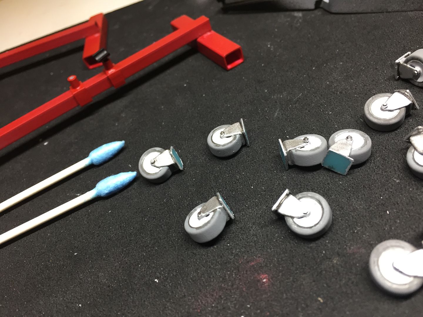
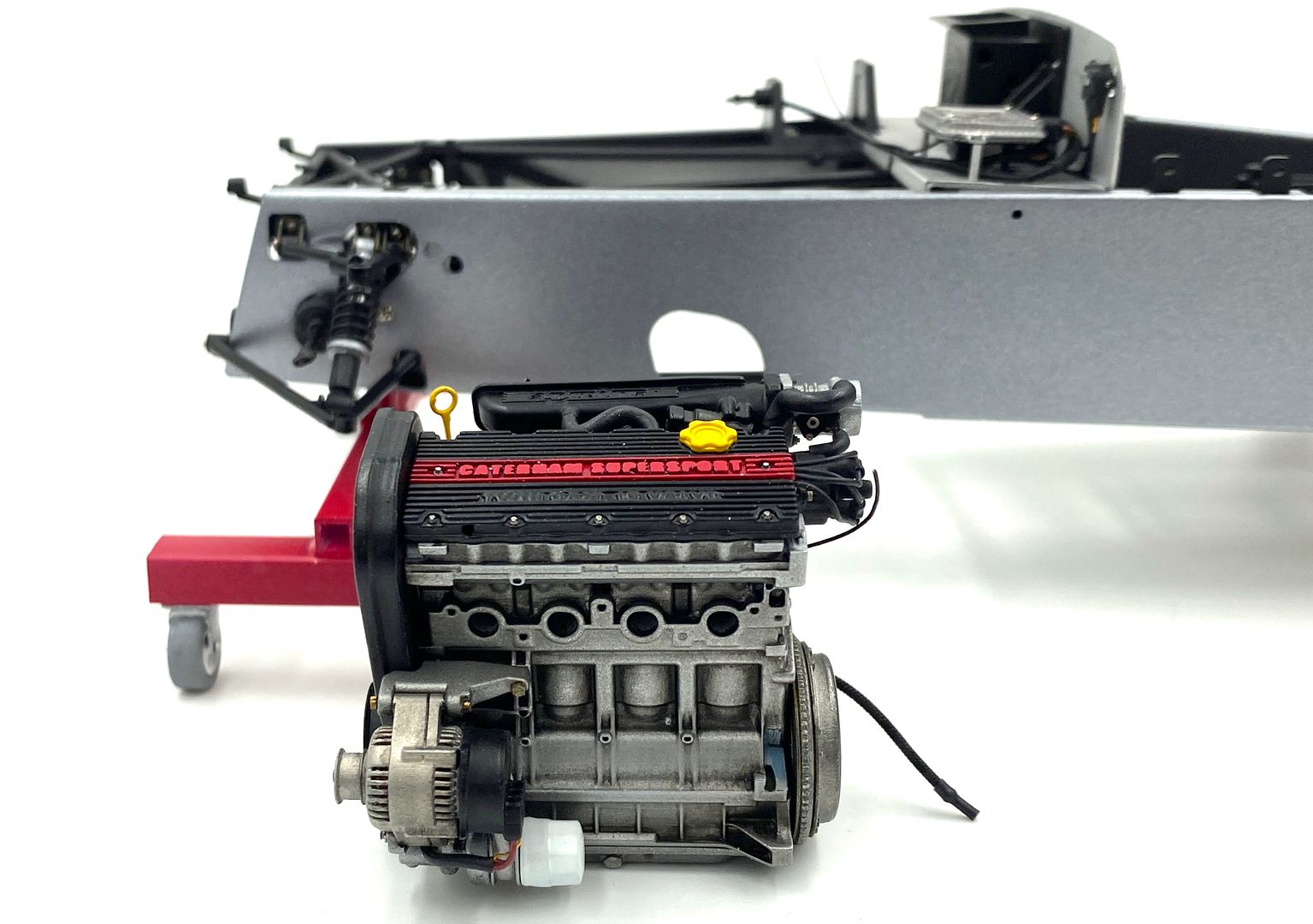
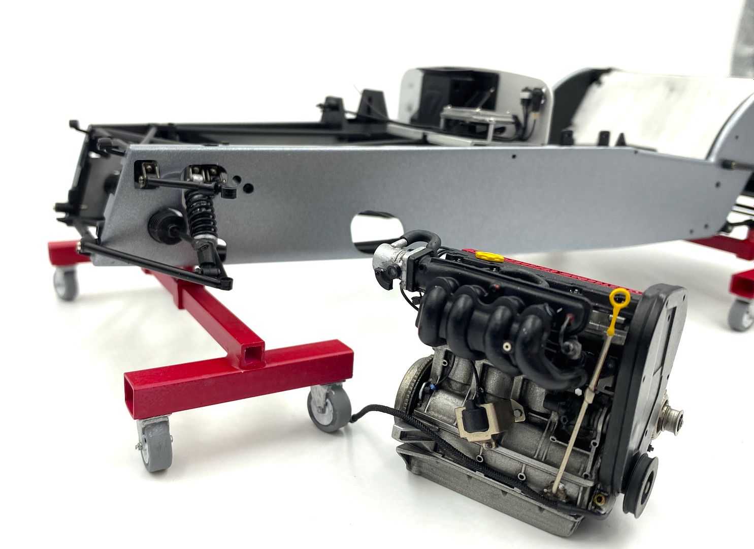
Result! Engine crane and support next...
...more of that later.
Simple plastic tube and I drew up and 3D printed some castors.


Result! Engine crane and support next...


...more of that later.
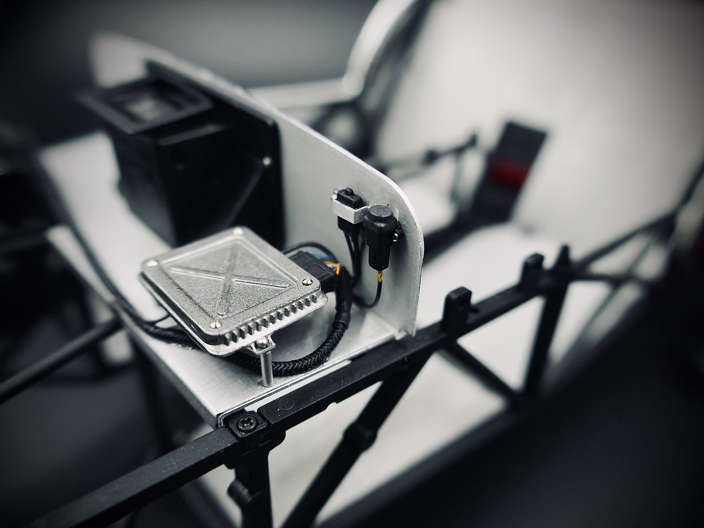
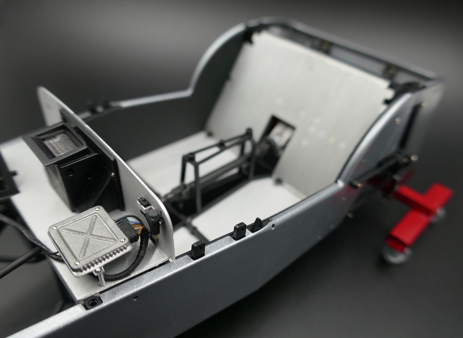
As on previous models, the detail in the engine bay is a highlight of these models - I made a start on the ECU/battery area.
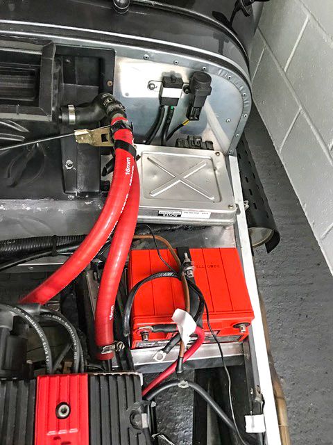
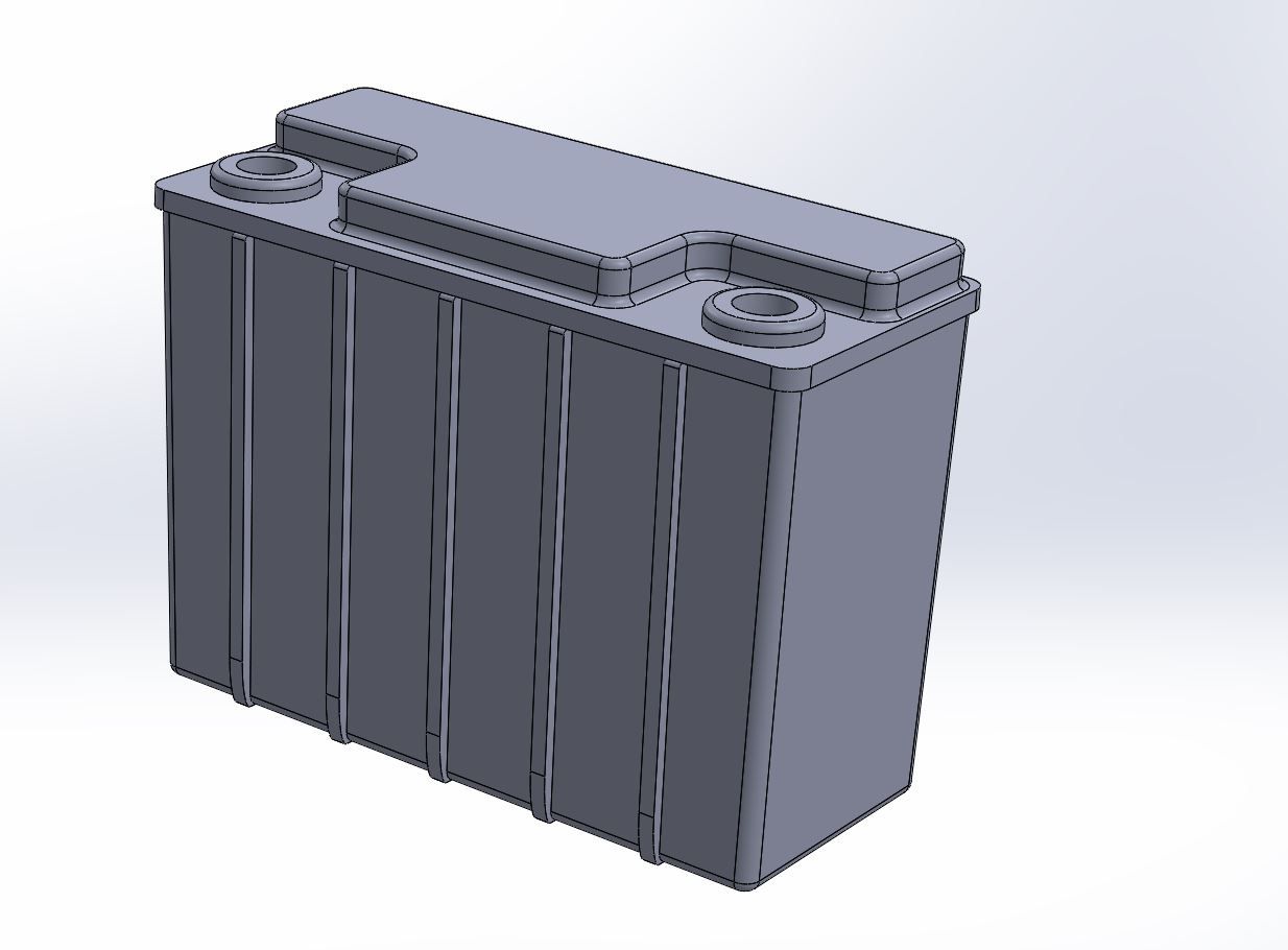
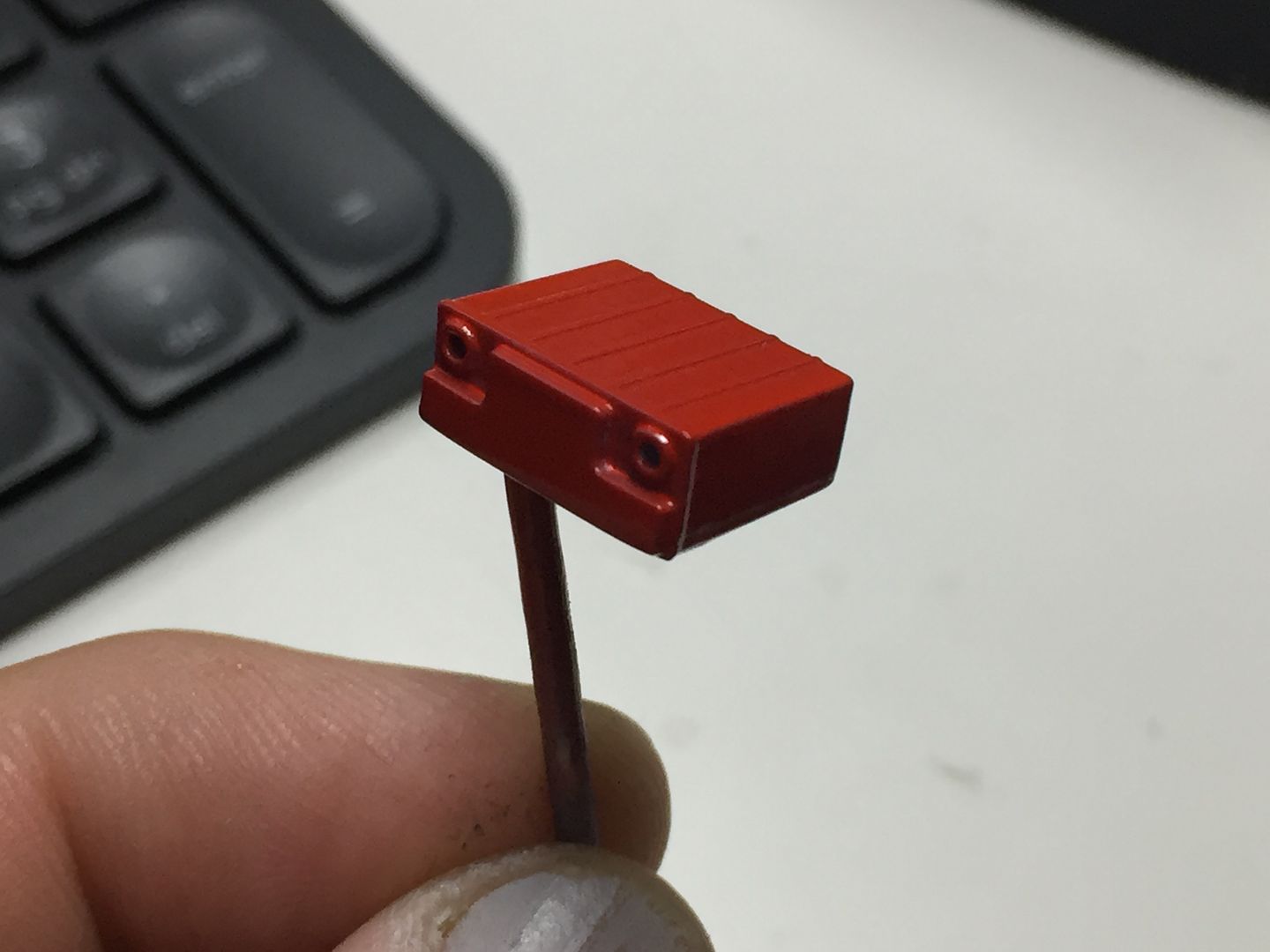
Richards car has a newer heater than the kit, so I referred to photos and drew it up in Solidworks, before printing it off...
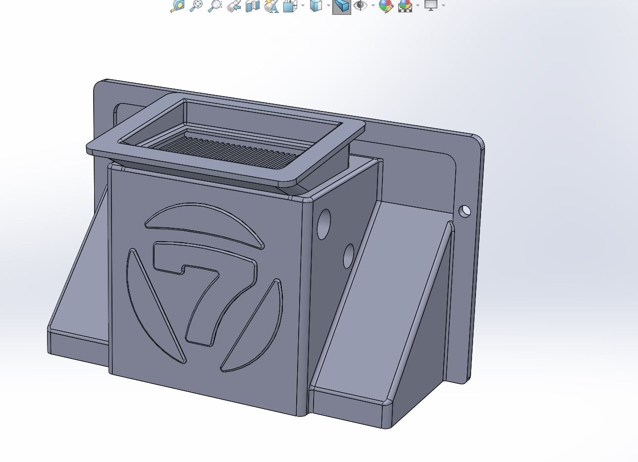
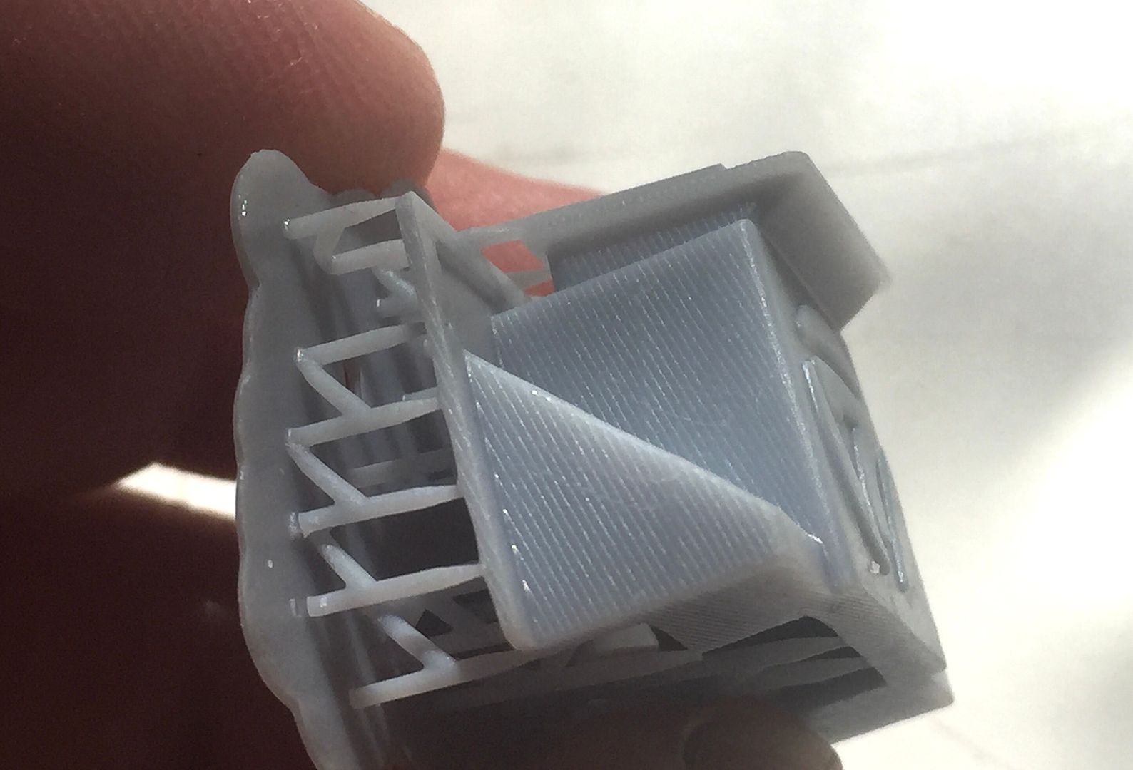
....I'll plumb that in later.
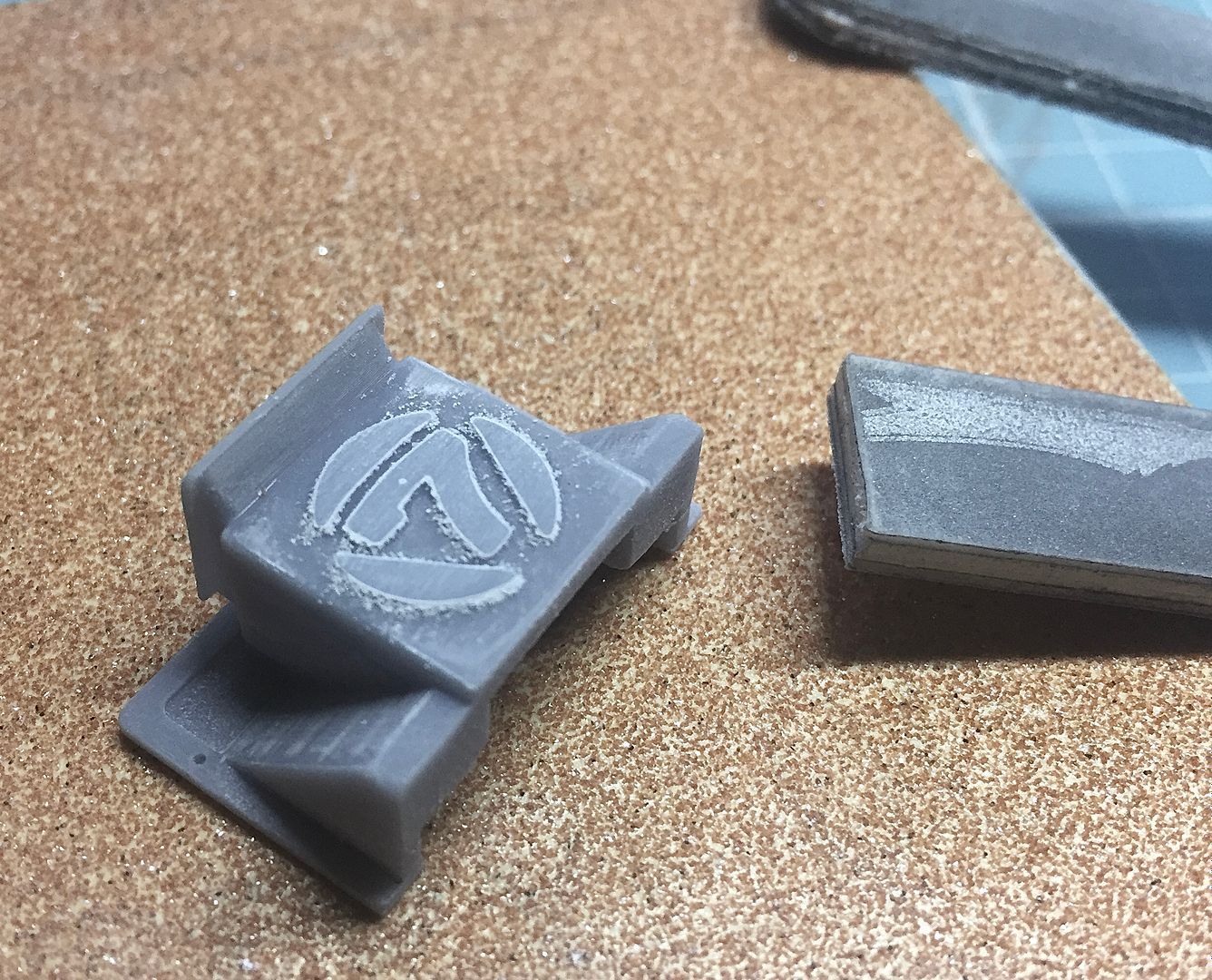
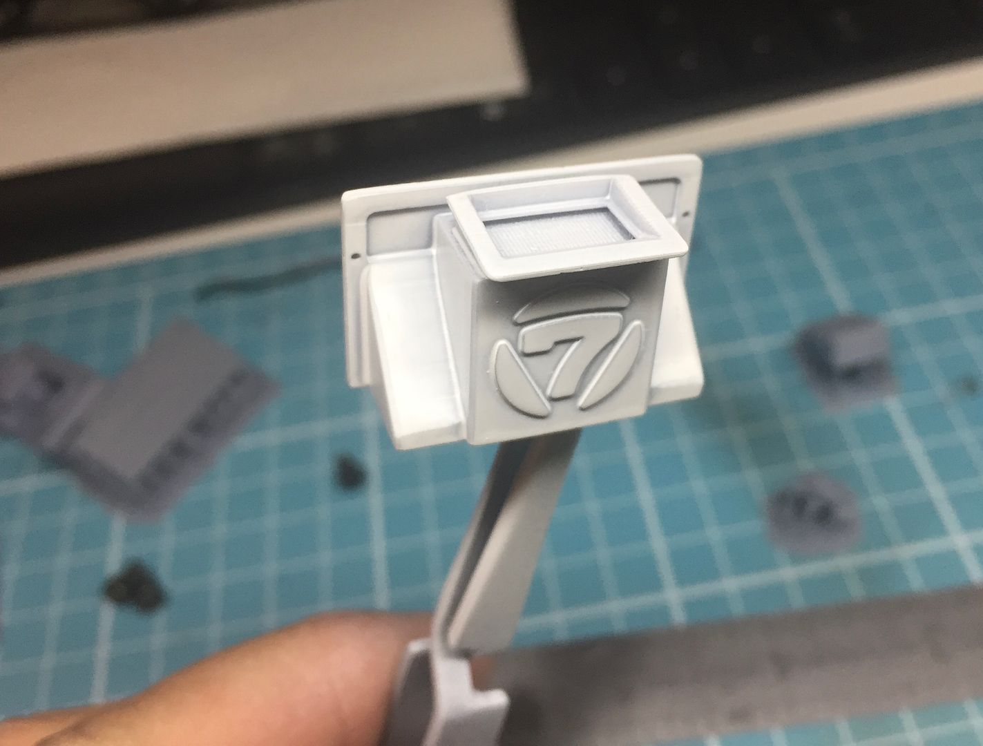
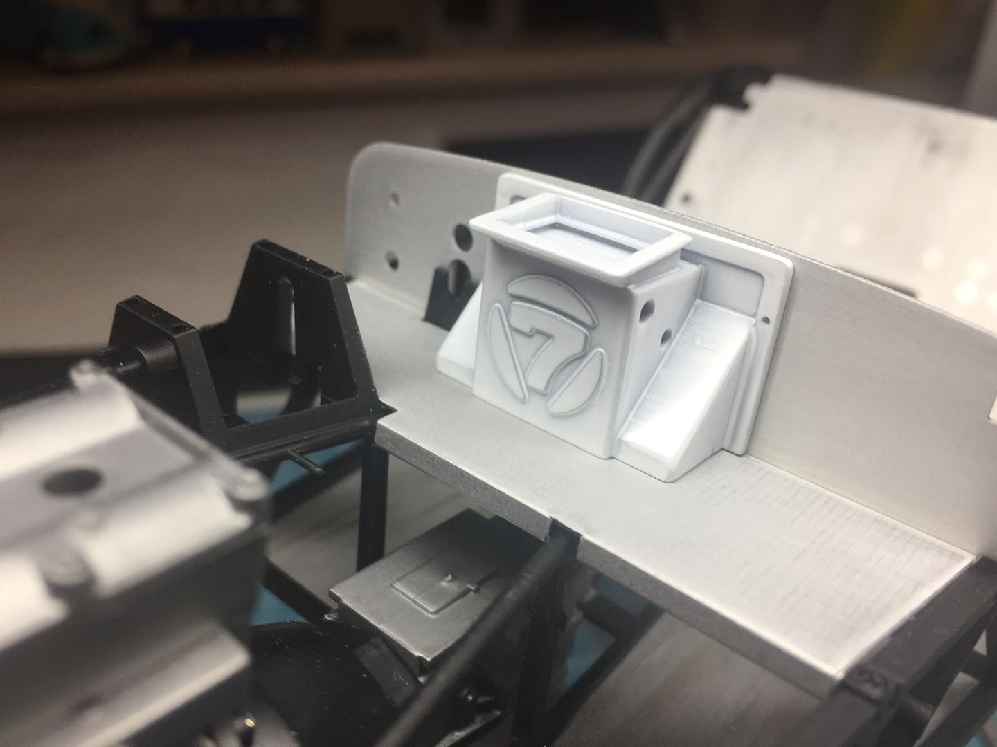
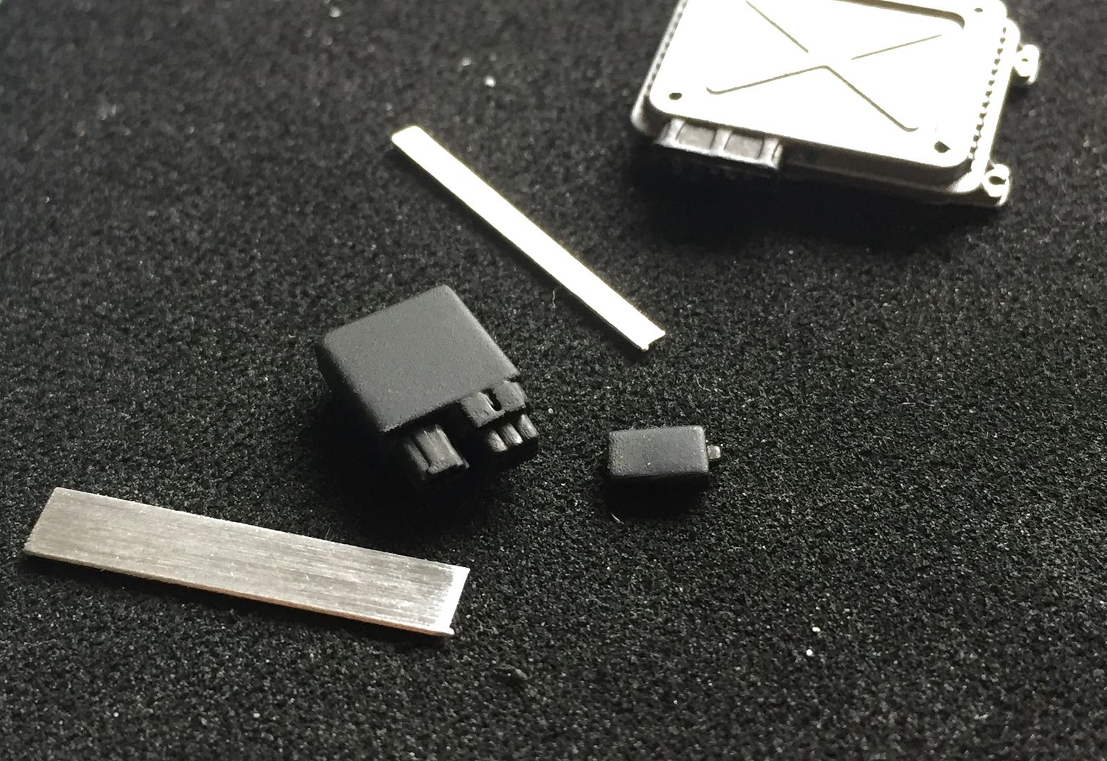
Next, the ECU and associated electrical relay boxes etc - again, drawn up in CAD and printed...
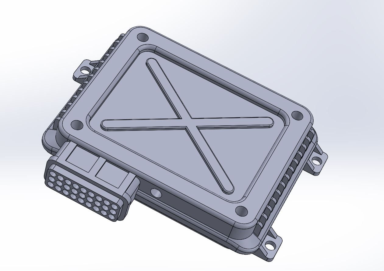
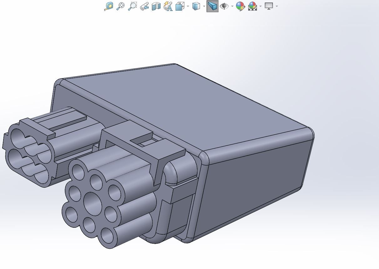
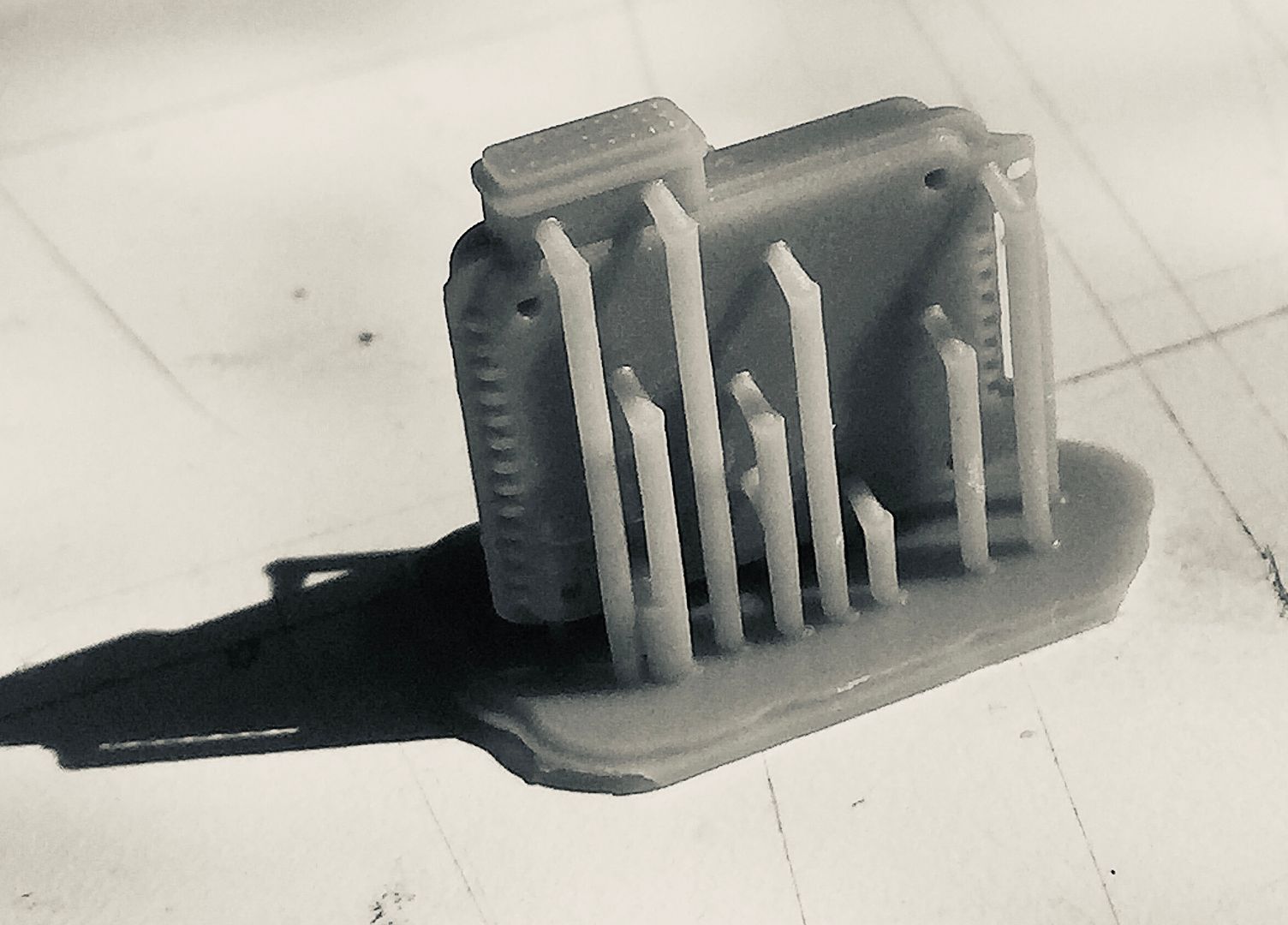
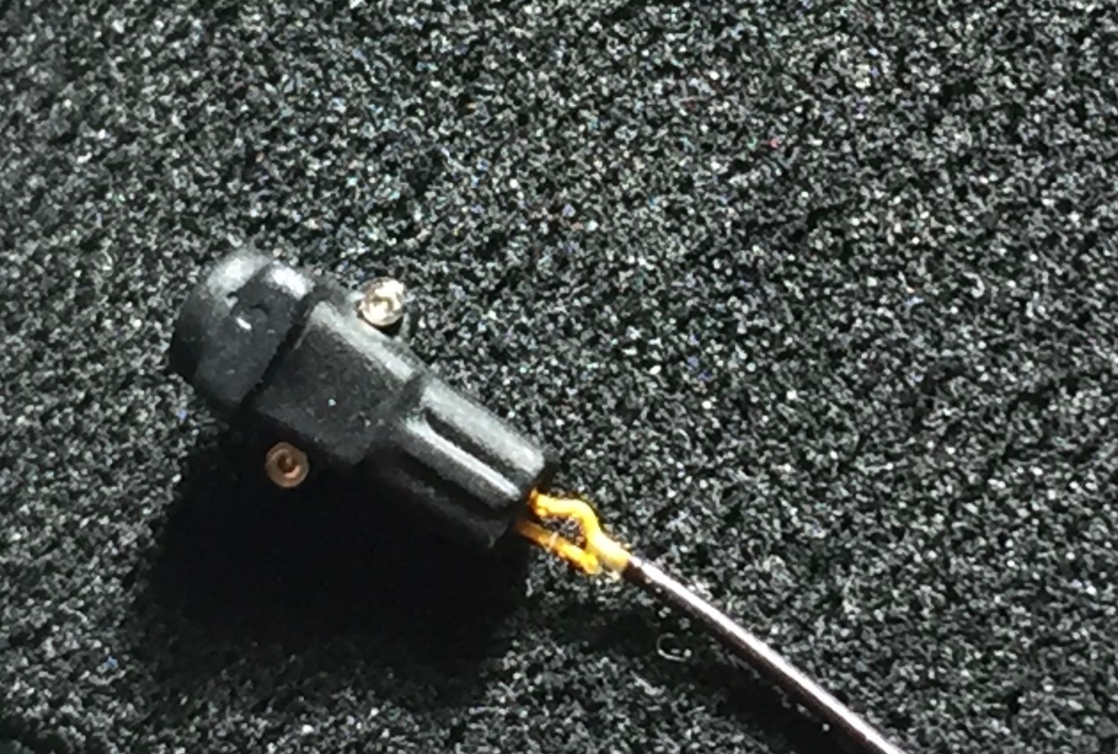
I tweaked the plugs to give me holes, as I intended to 'wire' the boxes for ultimate detail!
Once printed I drilled out the holes slightly to help my assembly - you can see 2 broken off drill bits in this photo!!
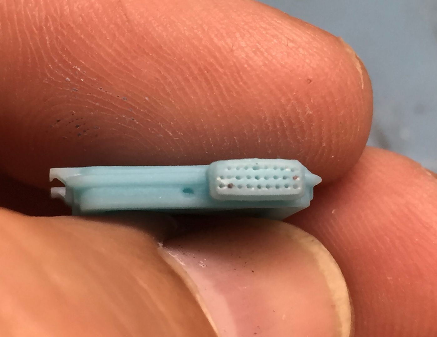
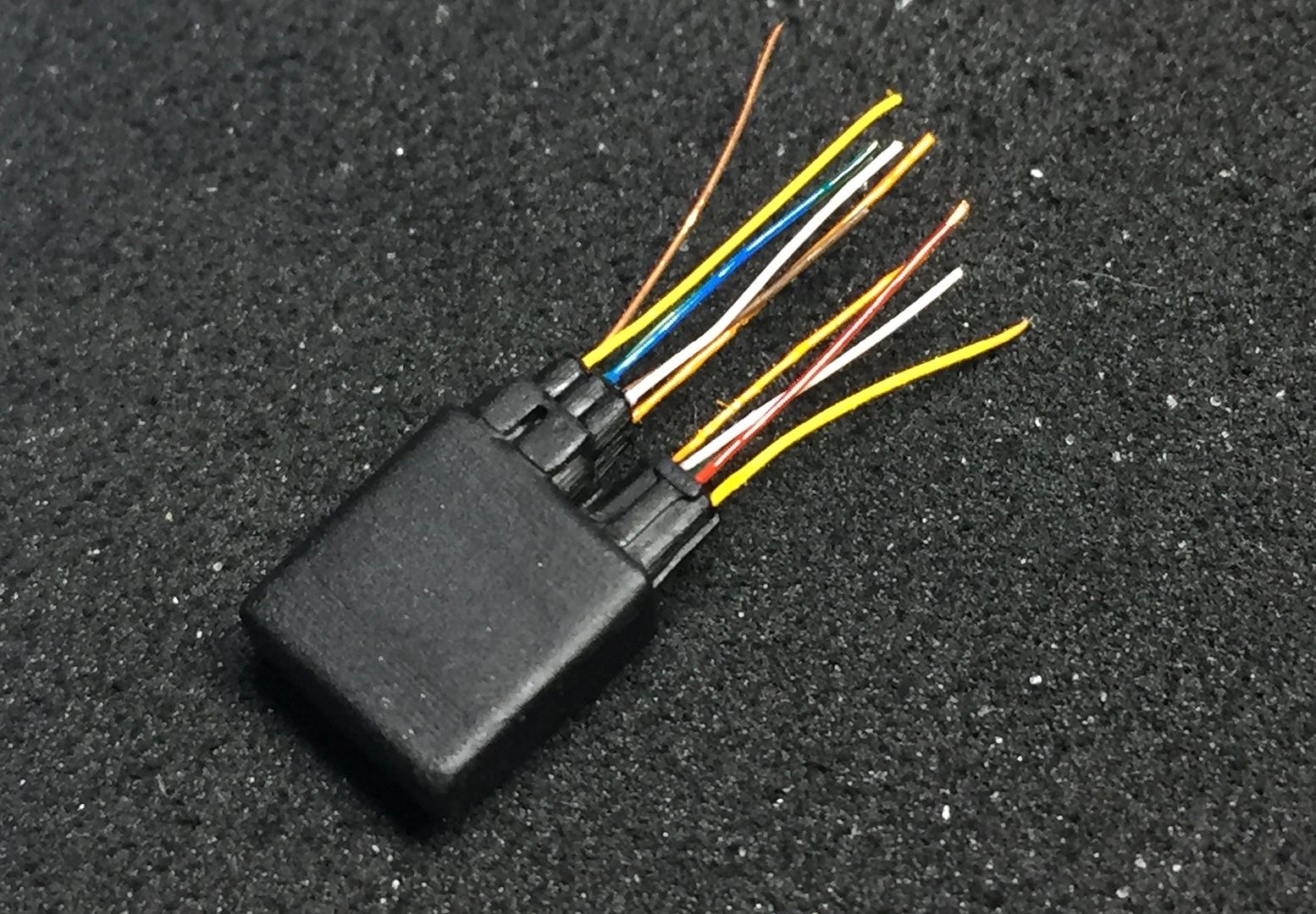
I took an electrical wire apart to get some really thin copper wire, and then painted this in lots of primary colours, so I could add the wiring...
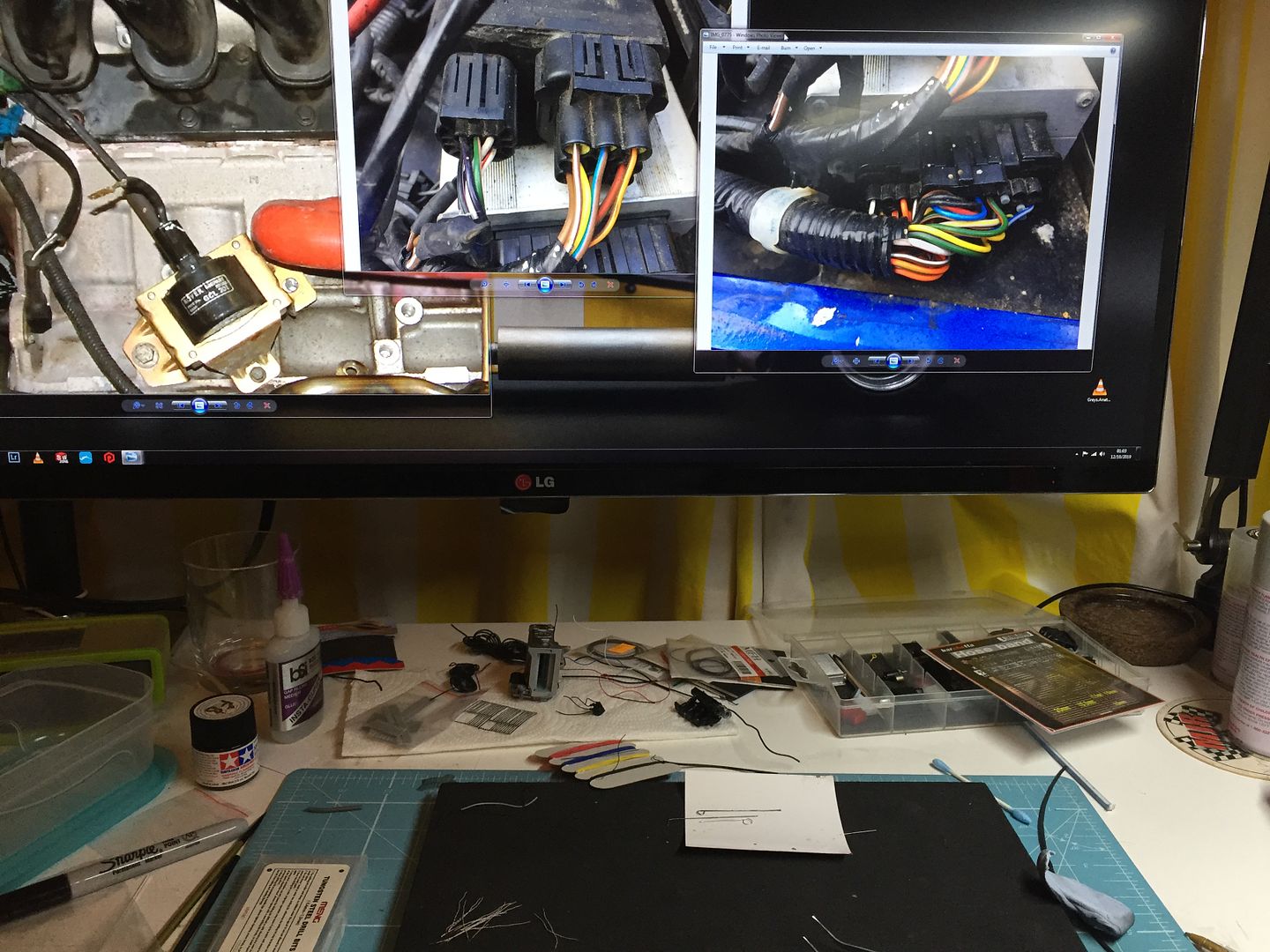
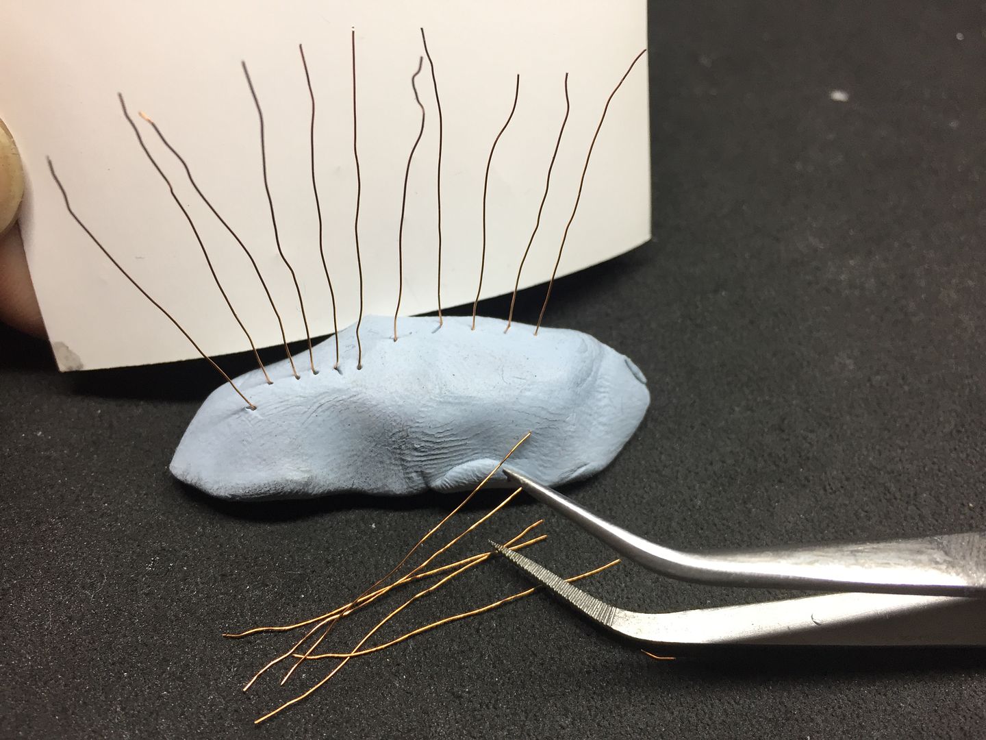
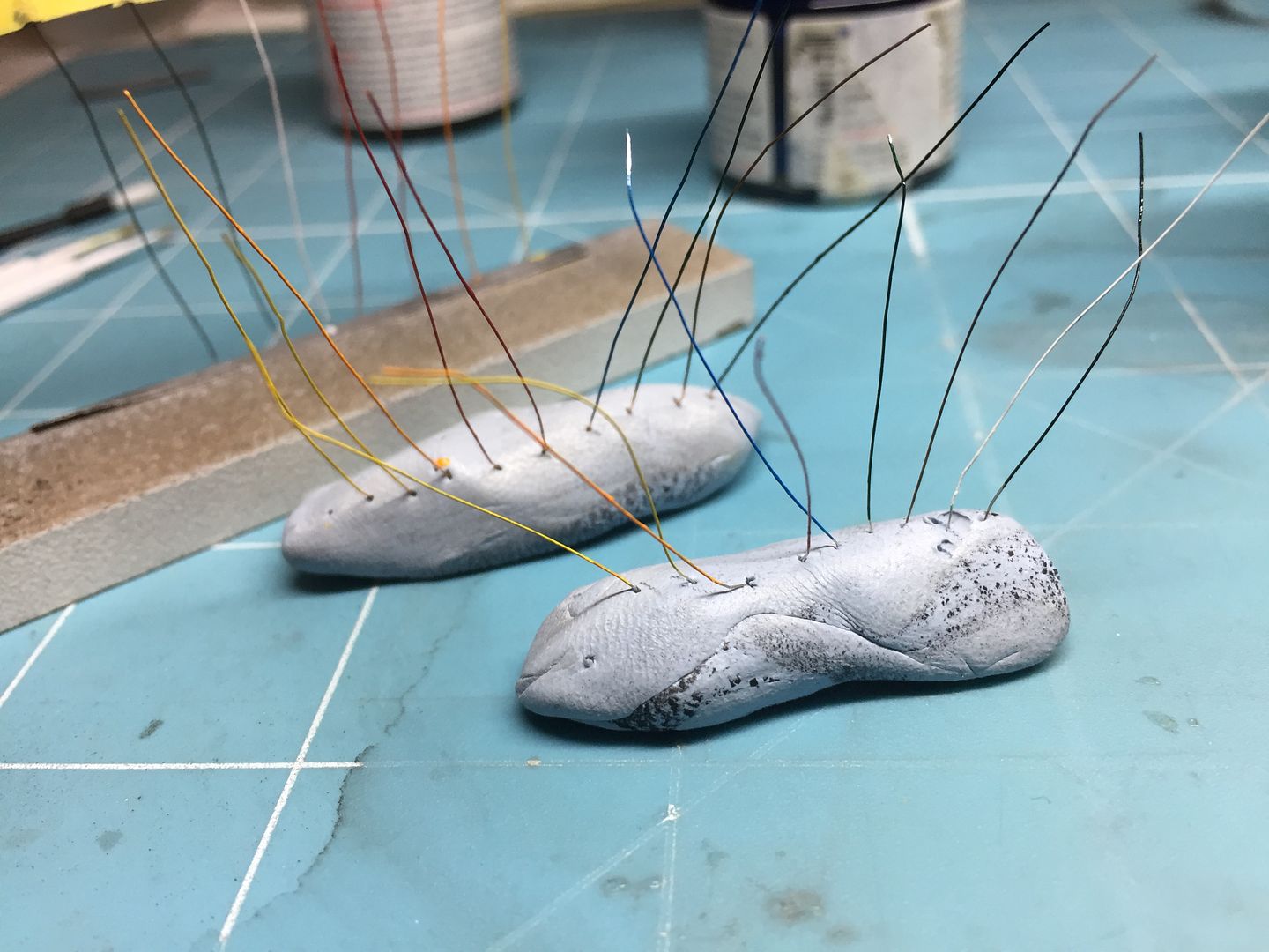
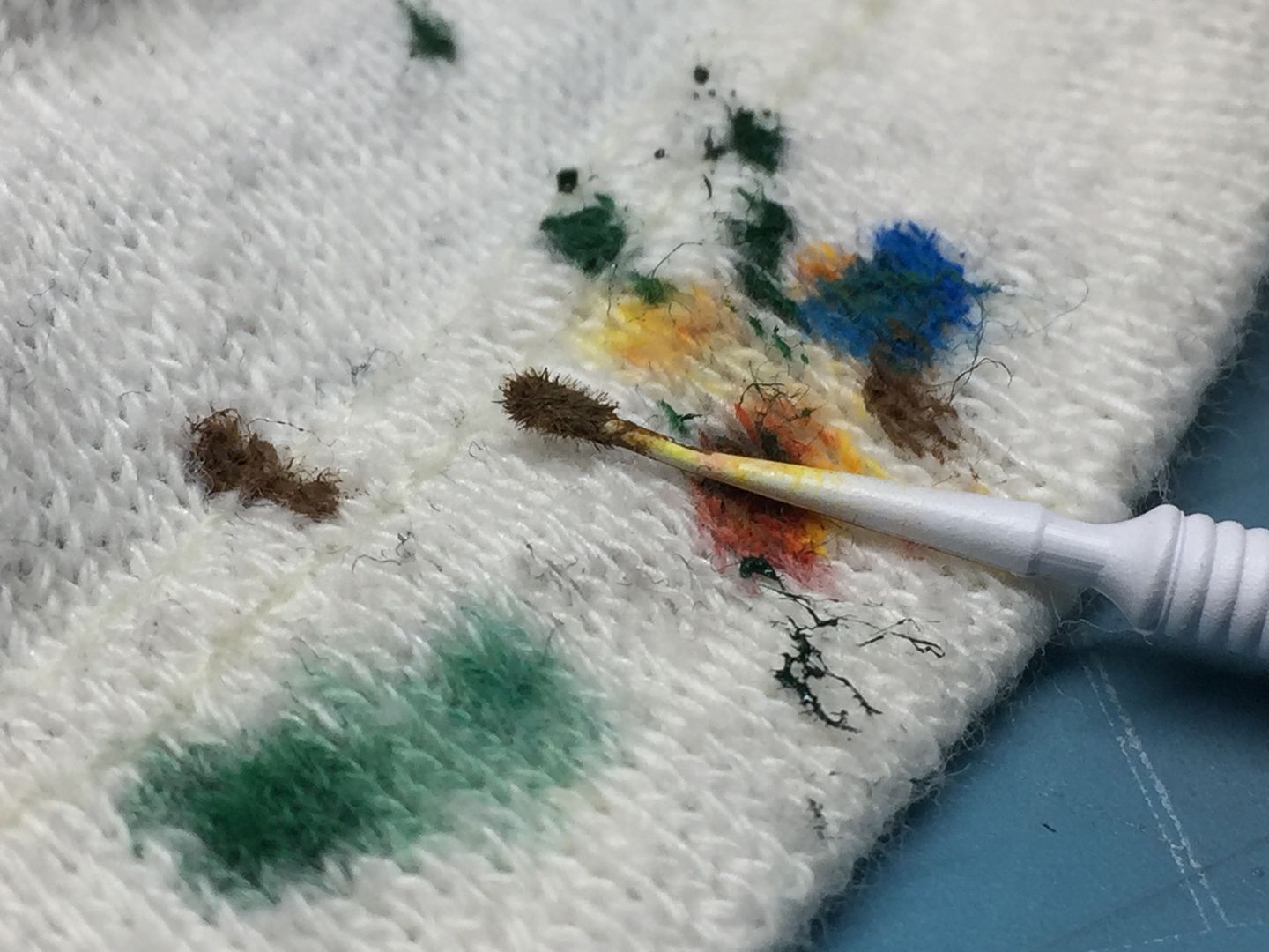
This was fiddly - but worth it for the result, IMO!
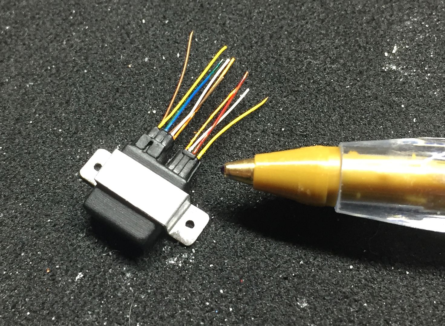
I then took the thinnest heat shrink tube I could find and stuffed the wire into it, before shrinking the tube VERY carefully, and bending the whole lot to suit...
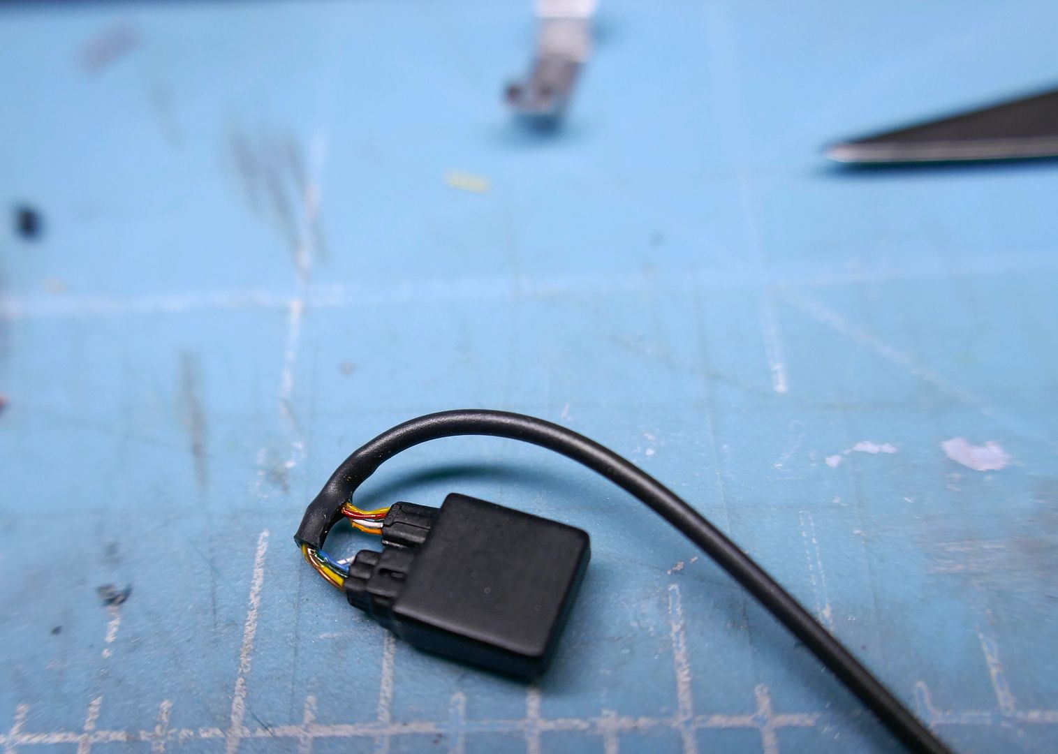
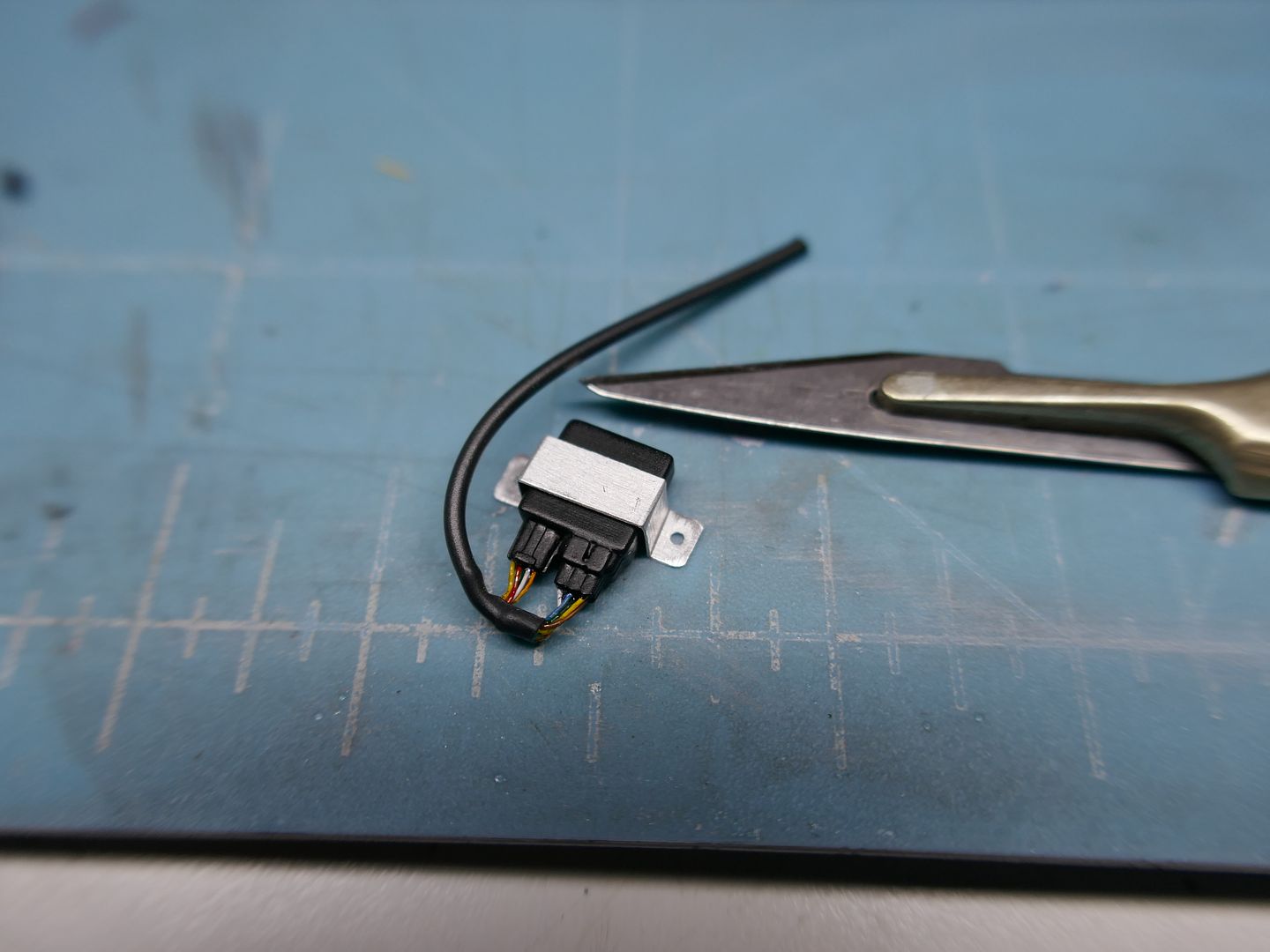
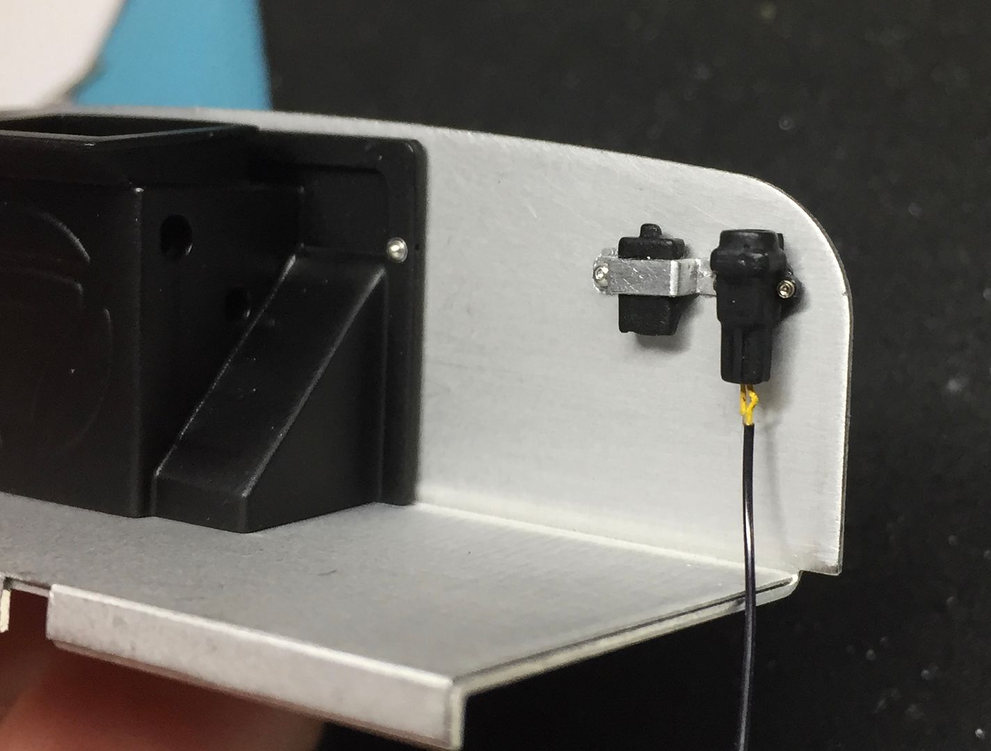
...and the ECU box (now painted) - a LOT of wires!
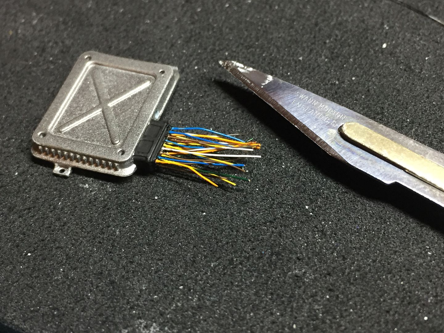
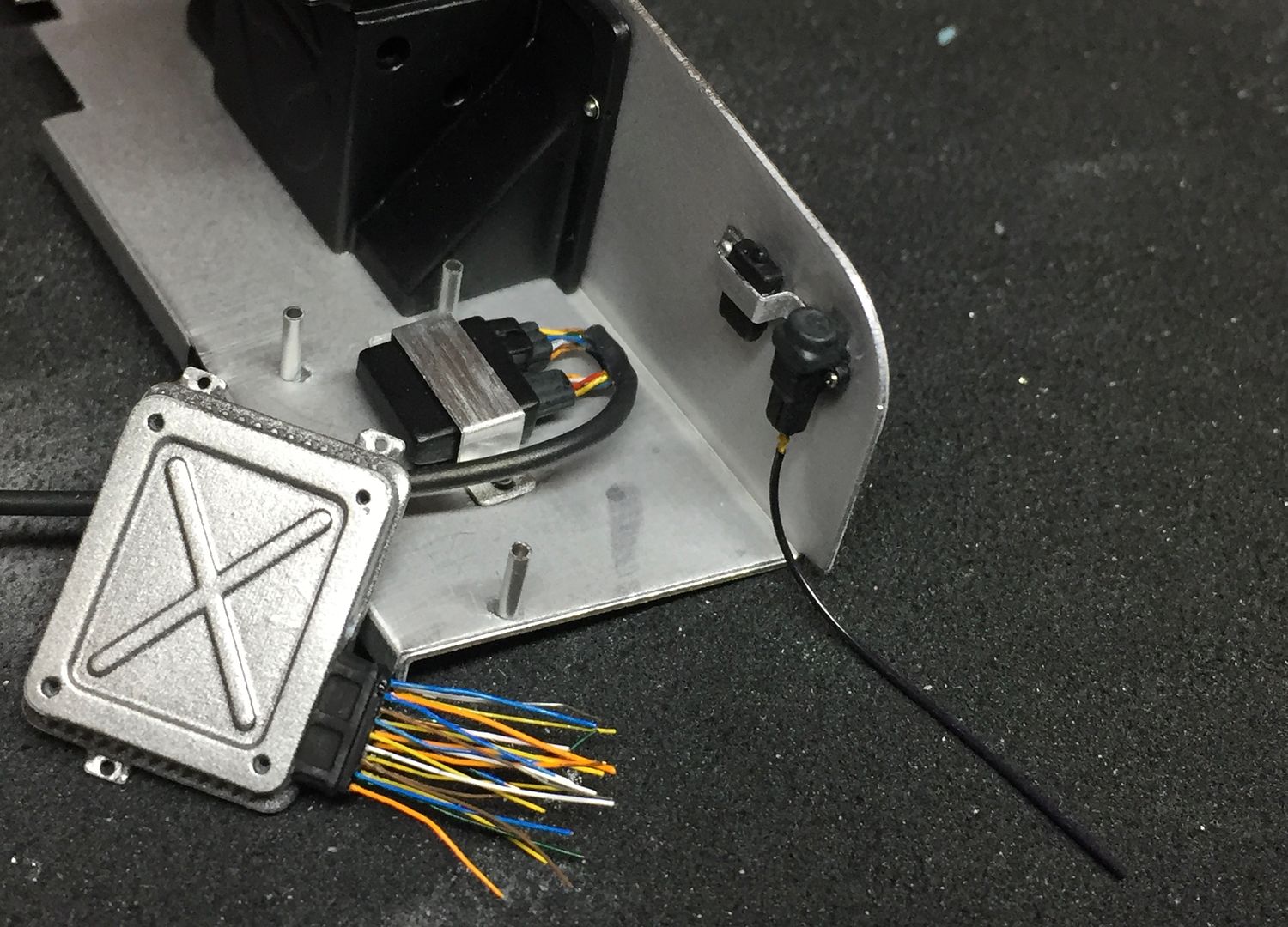
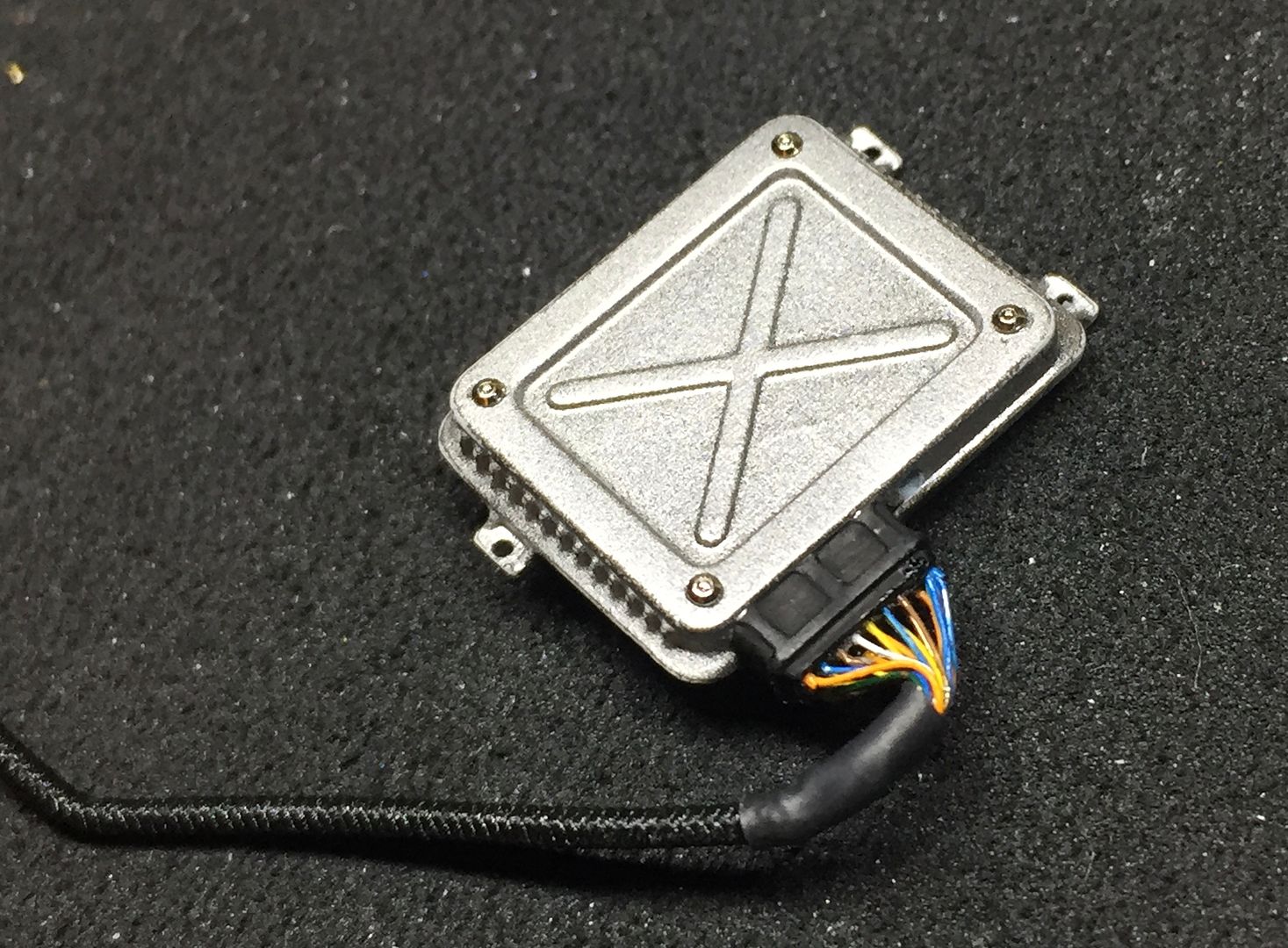
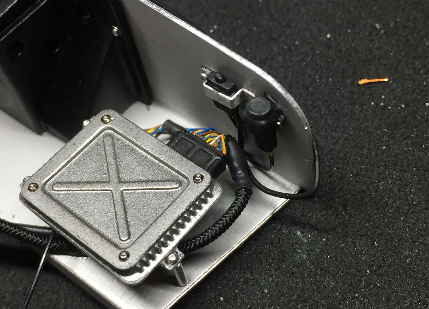
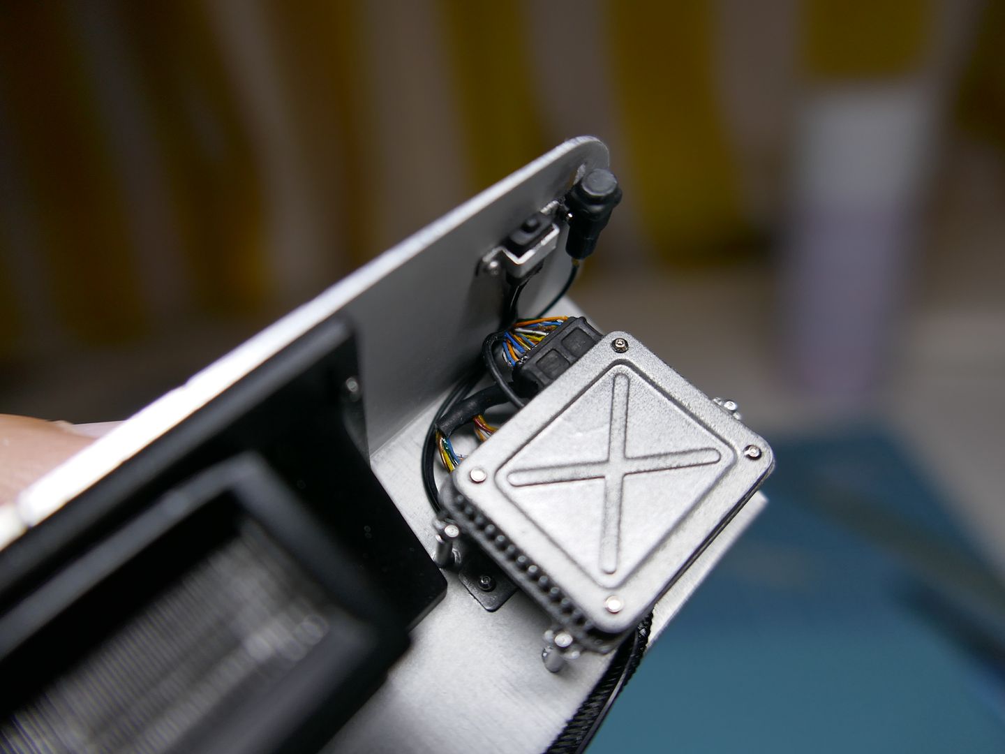
...small piece of heat shrink, and a piece of elastic thread to look like the wiring loom. Used some ali tube for the ecu supports.


Richards car has a newer heater than the kit, so I referred to photos and drew it up in Solidworks, before printing it off...


....I'll plumb that in later.
Next, the ECU and associated electrical relay boxes etc - again, drawn up in CAD and printed...


I tweaked the plugs to give me holes, as I intended to 'wire' the boxes for ultimate detail!
Once printed I drilled out the holes slightly to help my assembly - you can see 2 broken off drill bits in this photo!!

I took an electrical wire apart to get some really thin copper wire, and then painted this in lots of primary colours, so I could add the wiring...


This was fiddly - but worth it for the result, IMO!


I then took the thinnest heat shrink tube I could find and stuffed the wire into it, before shrinking the tube VERY carefully, and bending the whole lot to suit...


...and the ECU box (now painted) - a LOT of wires!


...small piece of heat shrink, and a piece of elastic thread to look like the wiring loom. Used some ali tube for the ecu supports.


Engine - so this is the big part!
Having scratch built the 2 engines on the R500's out of wood, plastic etc, machined slots in the cam cover etc etc, I wanted to 3D print these. But that meant drawing a k-series up in CAD. I'm self-teaching, so it was a bit daunting - but once you know where the buttons are, an engien block is not actually so complicated...
I took measurements from many photos I have of our engine over the years, and measured the engine outside in the car - which due to access is actually pretty difficult - I could measure the cam cover easily, but that was about it - but long story short, I was able to scale the photos once I had a base measurement. Once I had pretty much finished with the CAD and engine build, I had access to a real engine that was not in the car, and measuring this I found I had been pretty damn close.
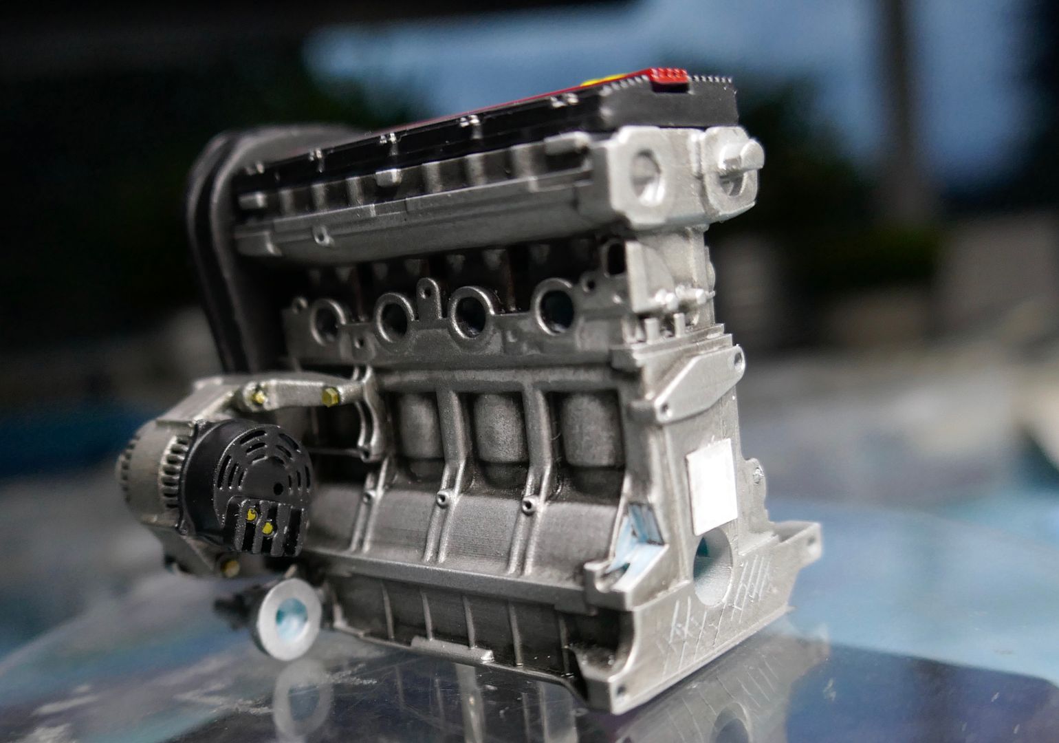
I drew the engine 1:1 (I can scale when I print) and I have split it into the actual parts - so the block consists of 5-6 'layers' (although I printed the middle bits in one lump) I found out that the easiest way to model and build the engine is to do it exactly the same as the real one - so the alternator is attached with a bracket in the same way as 1:1, coil is bolted on the same way, throttle uses 4 bolts etc etc.
I had a few parts lying around - like the sump - which I was able to measure properly and then scale others from that.
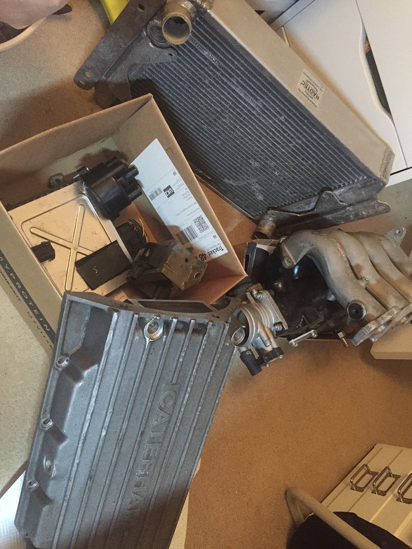
Richards car has the plastic Rover air intake, which was going to be a challenge to draw for me in CAD.


I started roughing out the overall shape - main measurements were the height of each layer in the block. Once I got those correct, I added most of the detail in by eye.
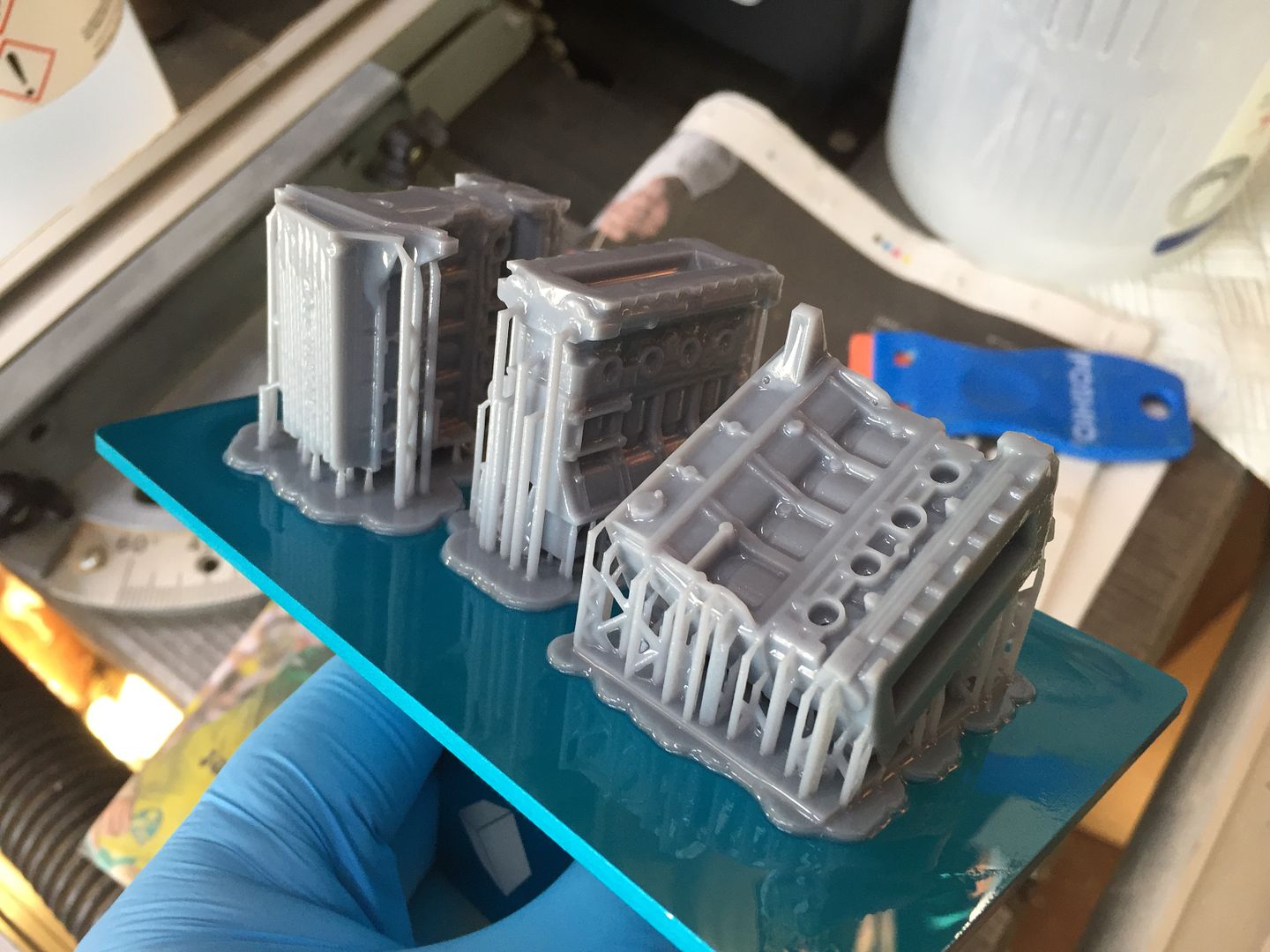
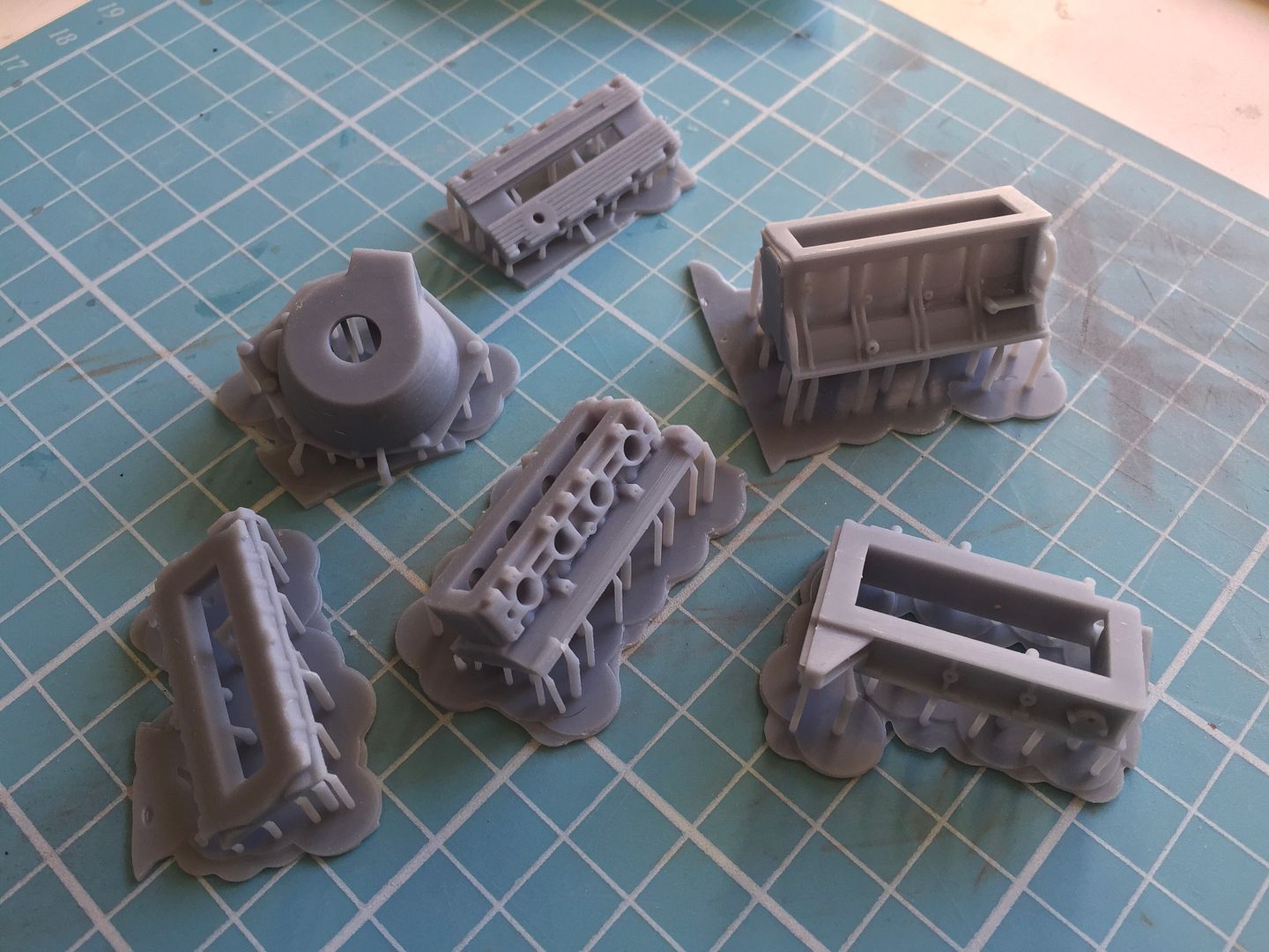
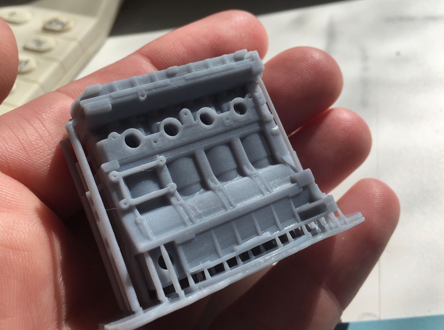
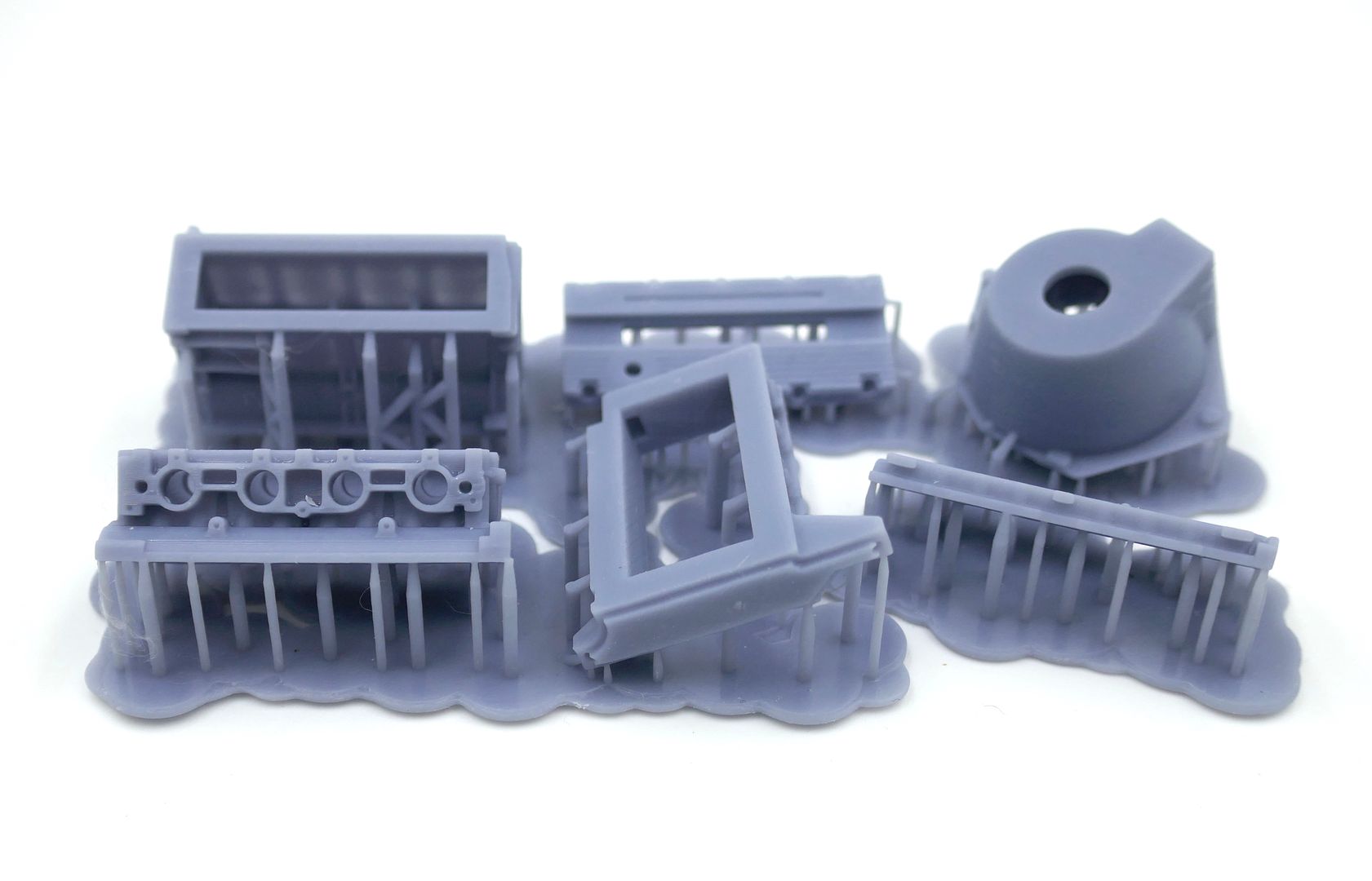
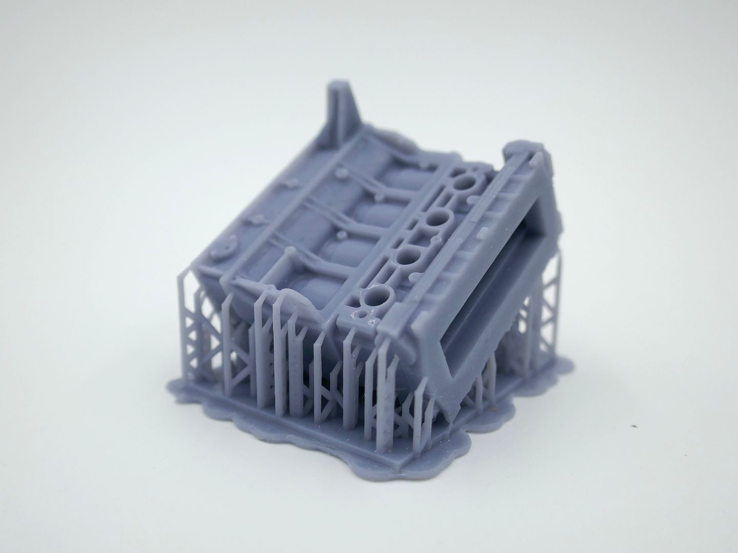
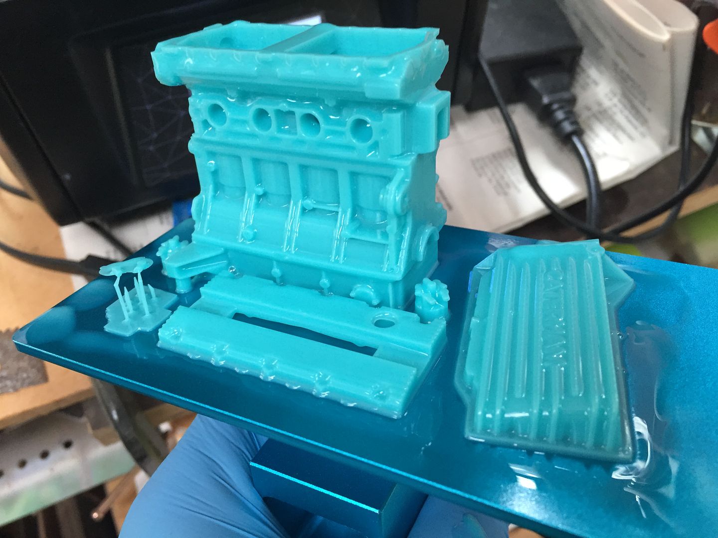
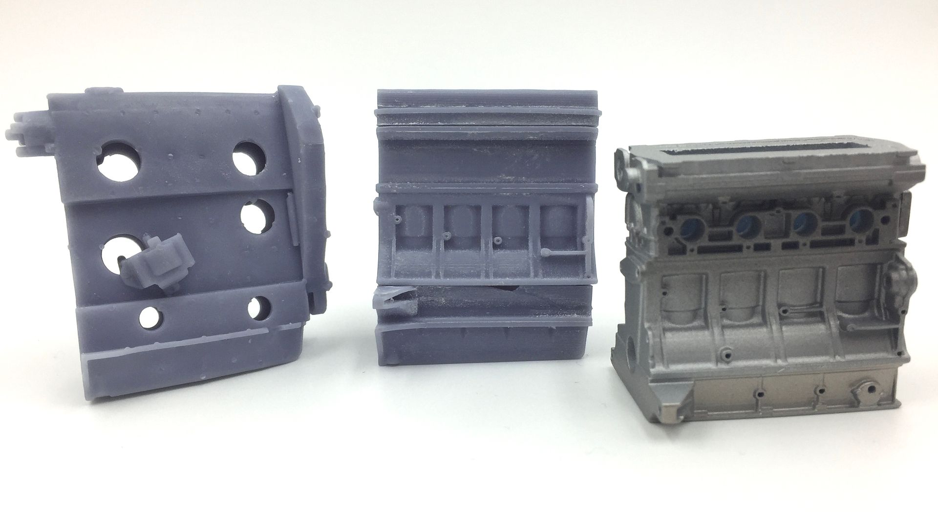
I printed a VERY rough block to see if the size/scale was going to work, then a slightly more refined version at different stages. I'm learning about the 3D printing as well, and you learn to design the parts to make the printing process - particularly the orientation on the build plate - easier. The large holes are for the resin to drain - I hollowed out the 'real' one later.
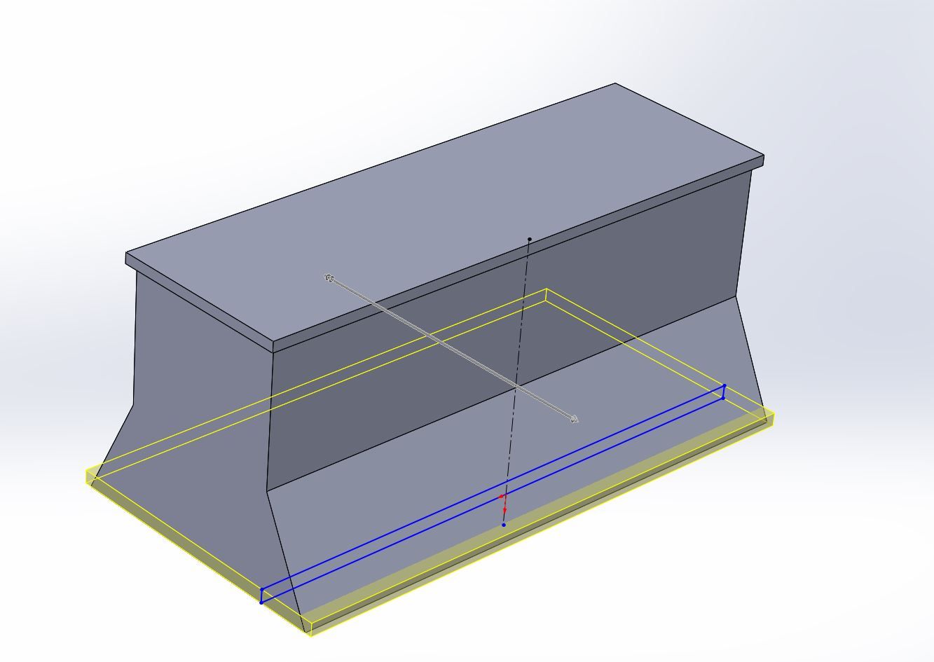
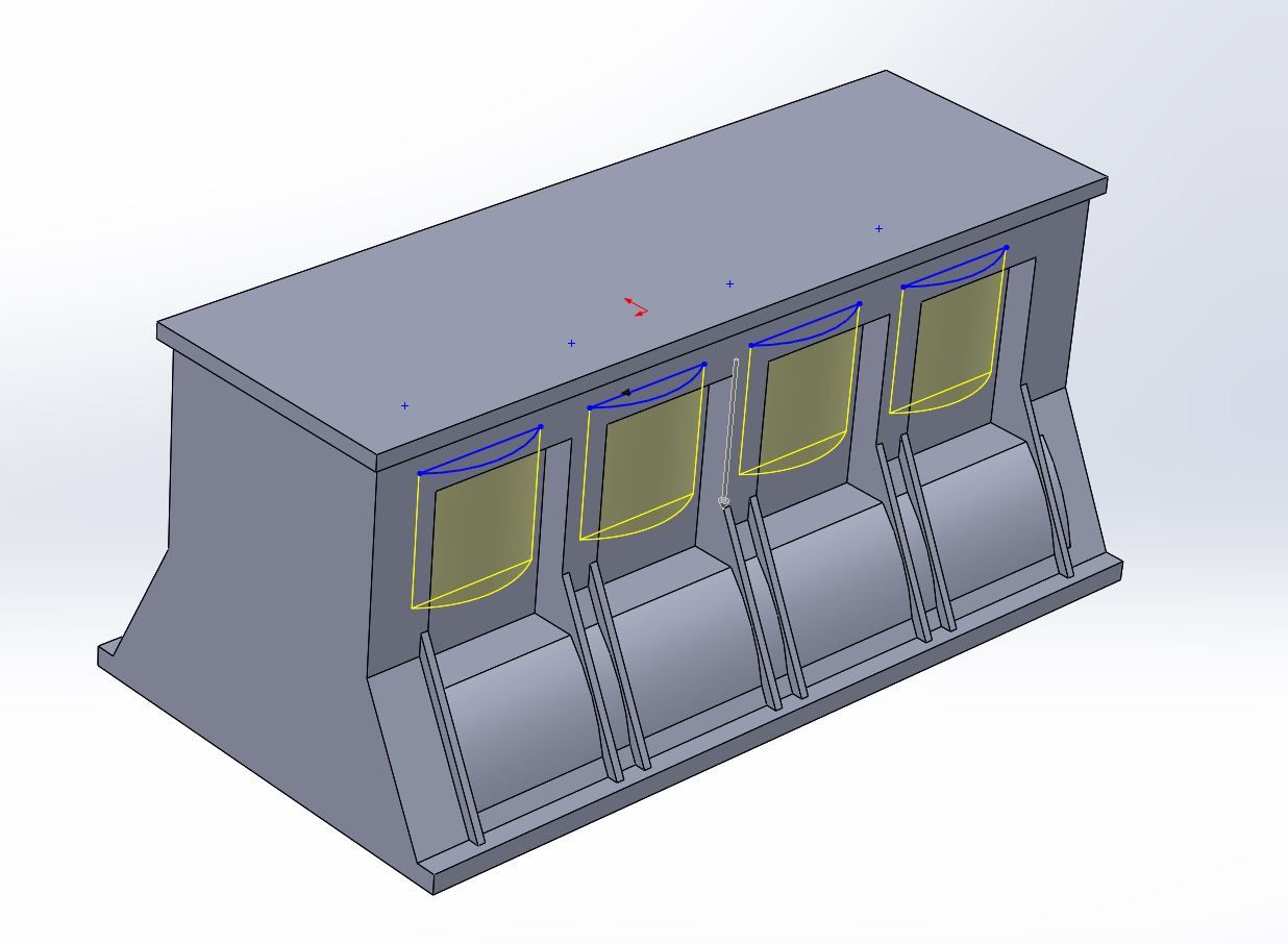
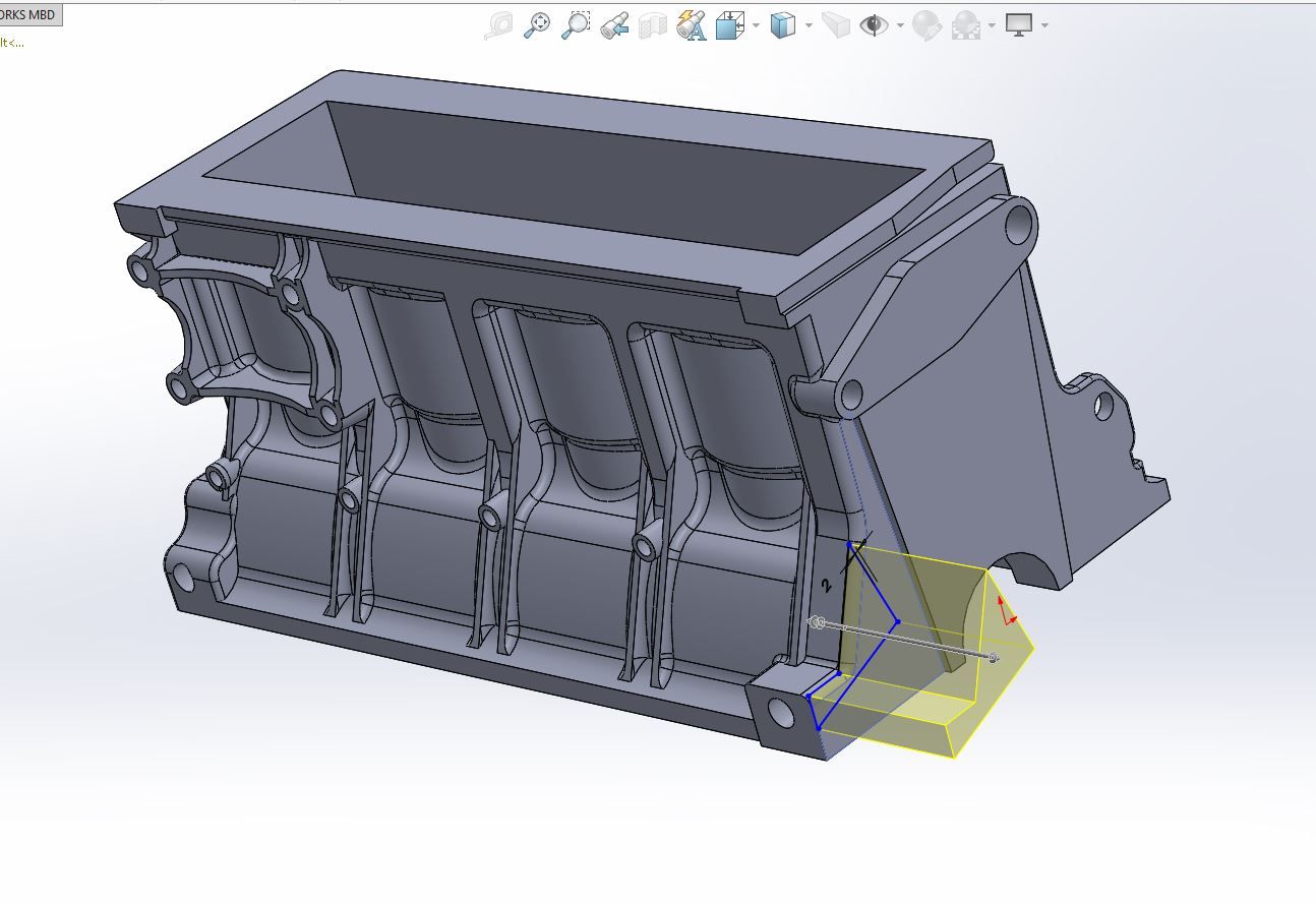
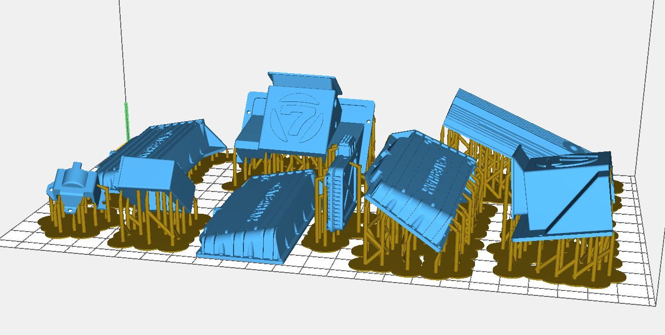
example of the 3d printer plate layout/slicing - where you add supports etc - I'm learning!
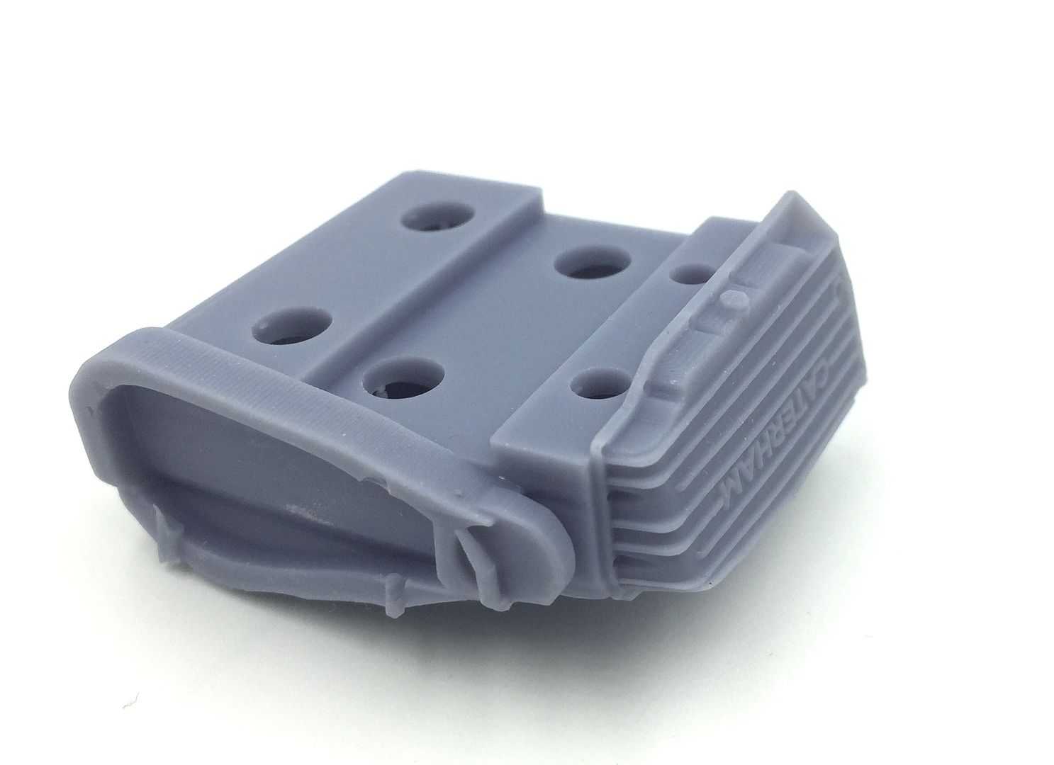
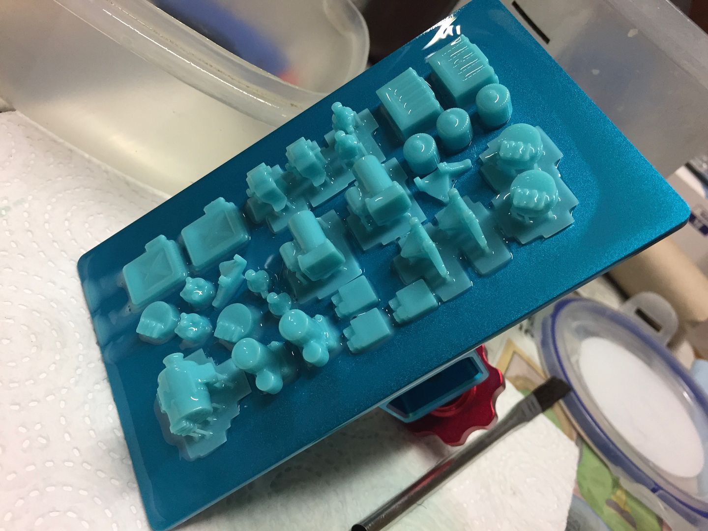
Some examples of parts being printed - there were lots of versions, so these photos cover about a months work from now on!
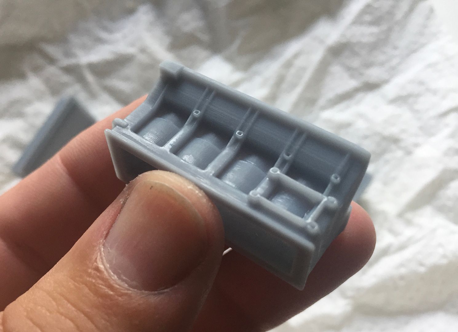
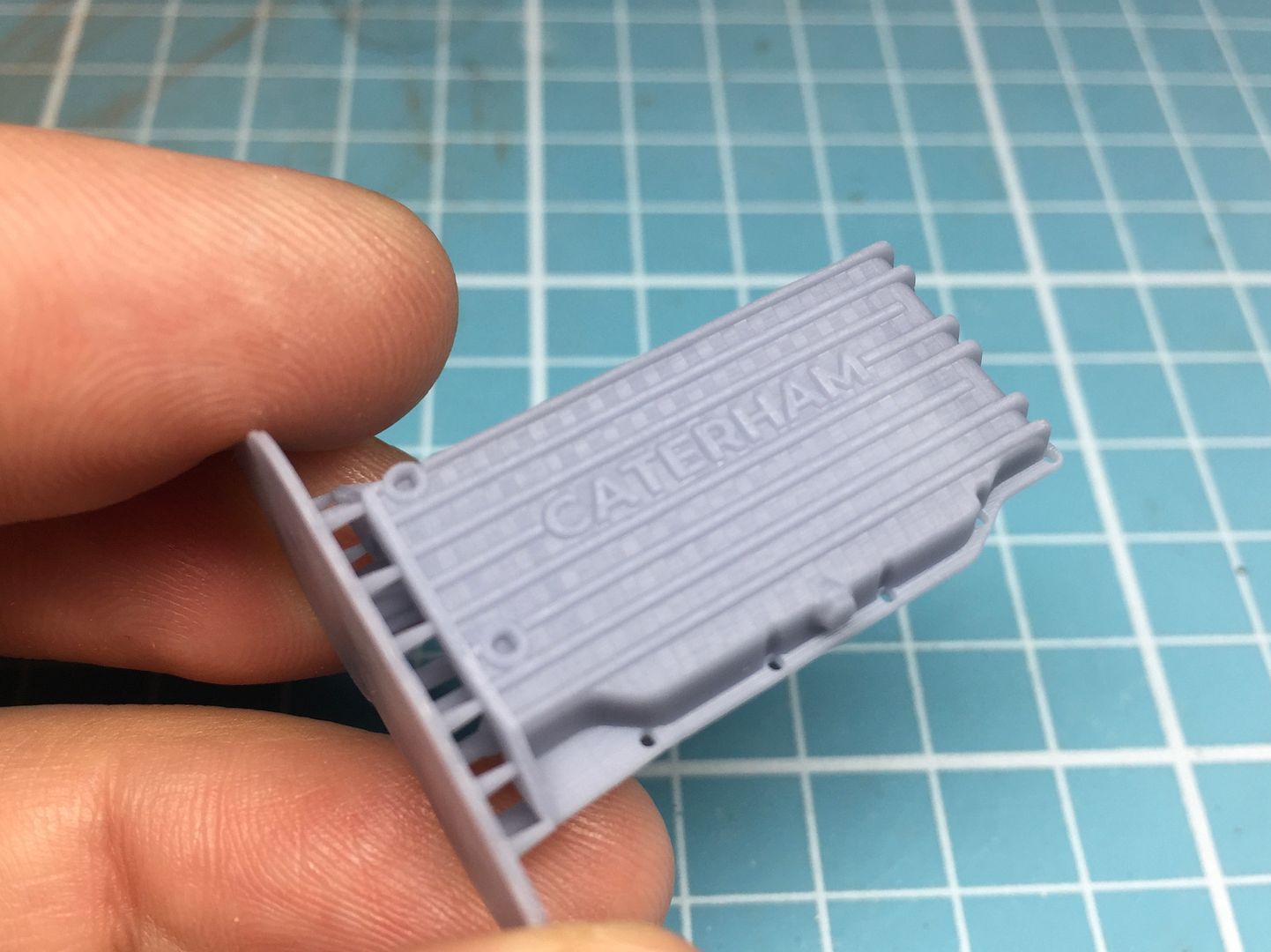
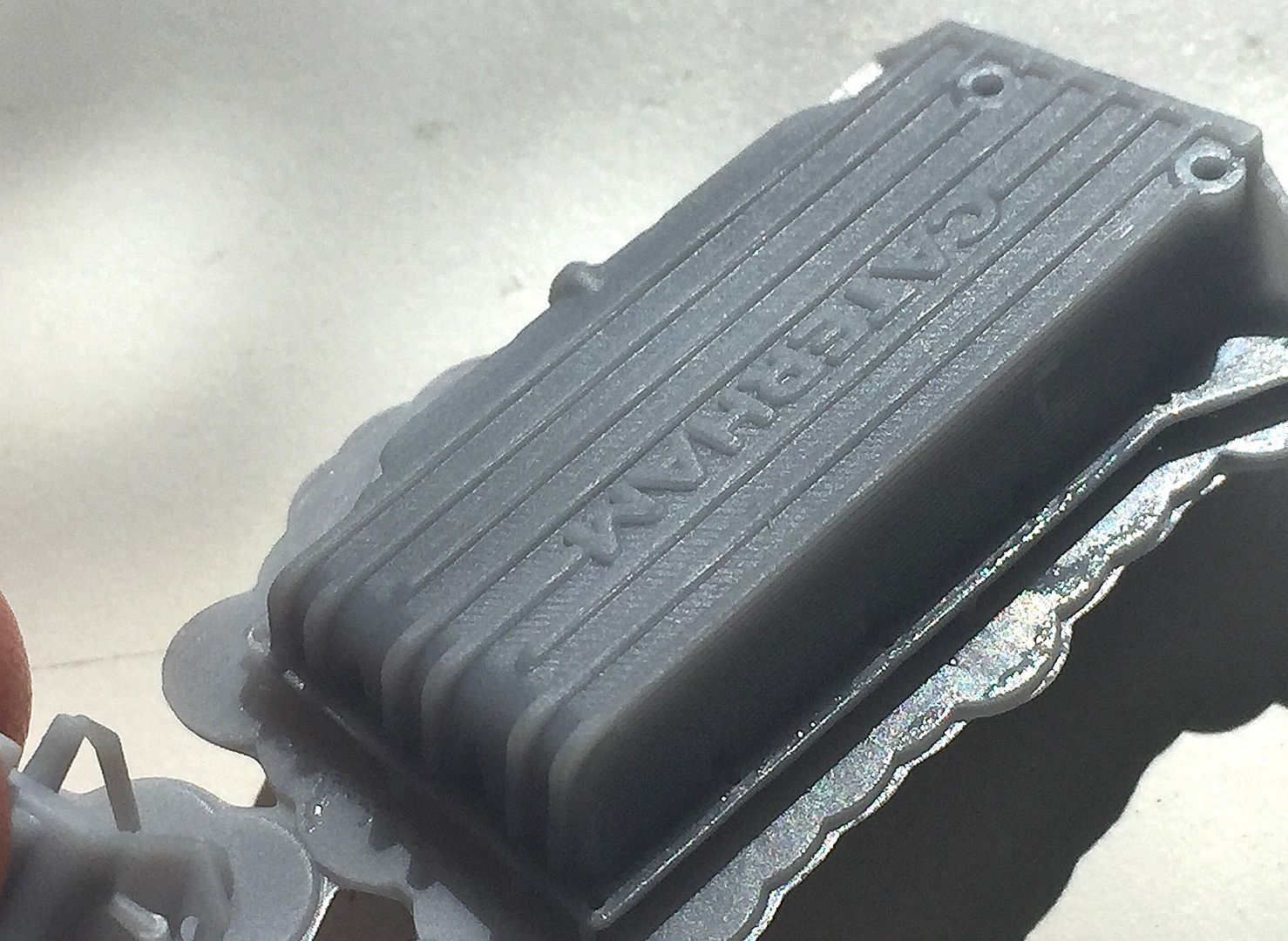
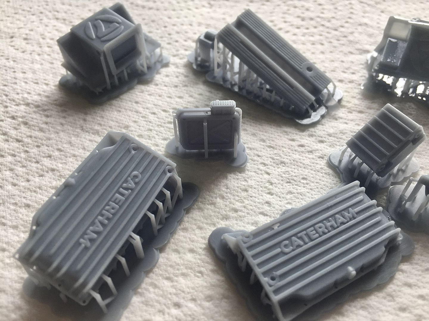
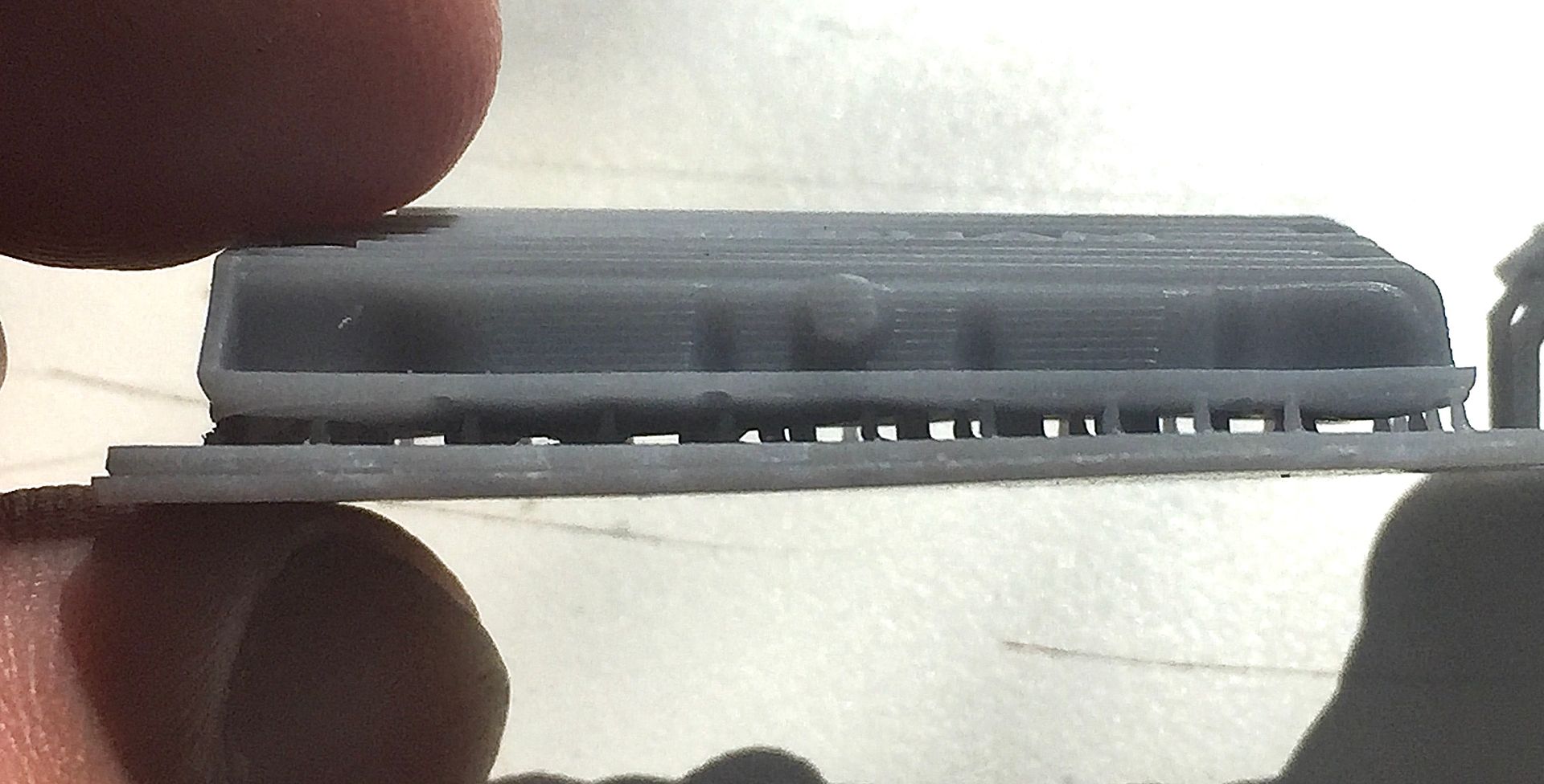
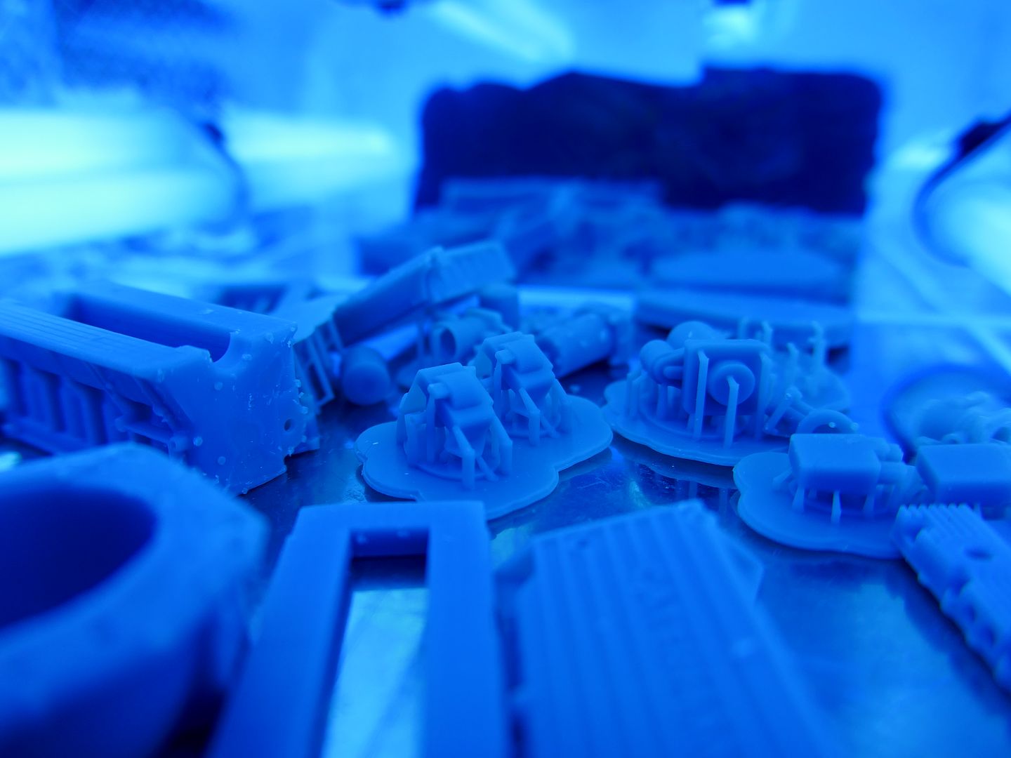
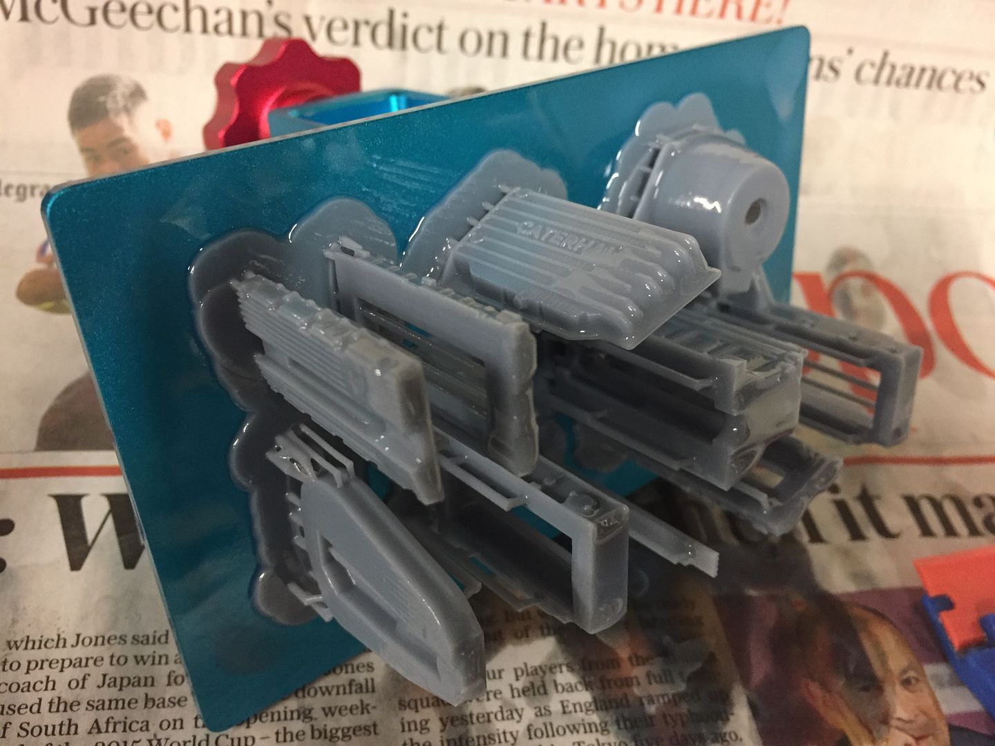
I'd do the occasional print with everything 'turned on' in the assembly, just to see the size etc - in the end, every component, like coil, sump, bellhousing etc was made separately.
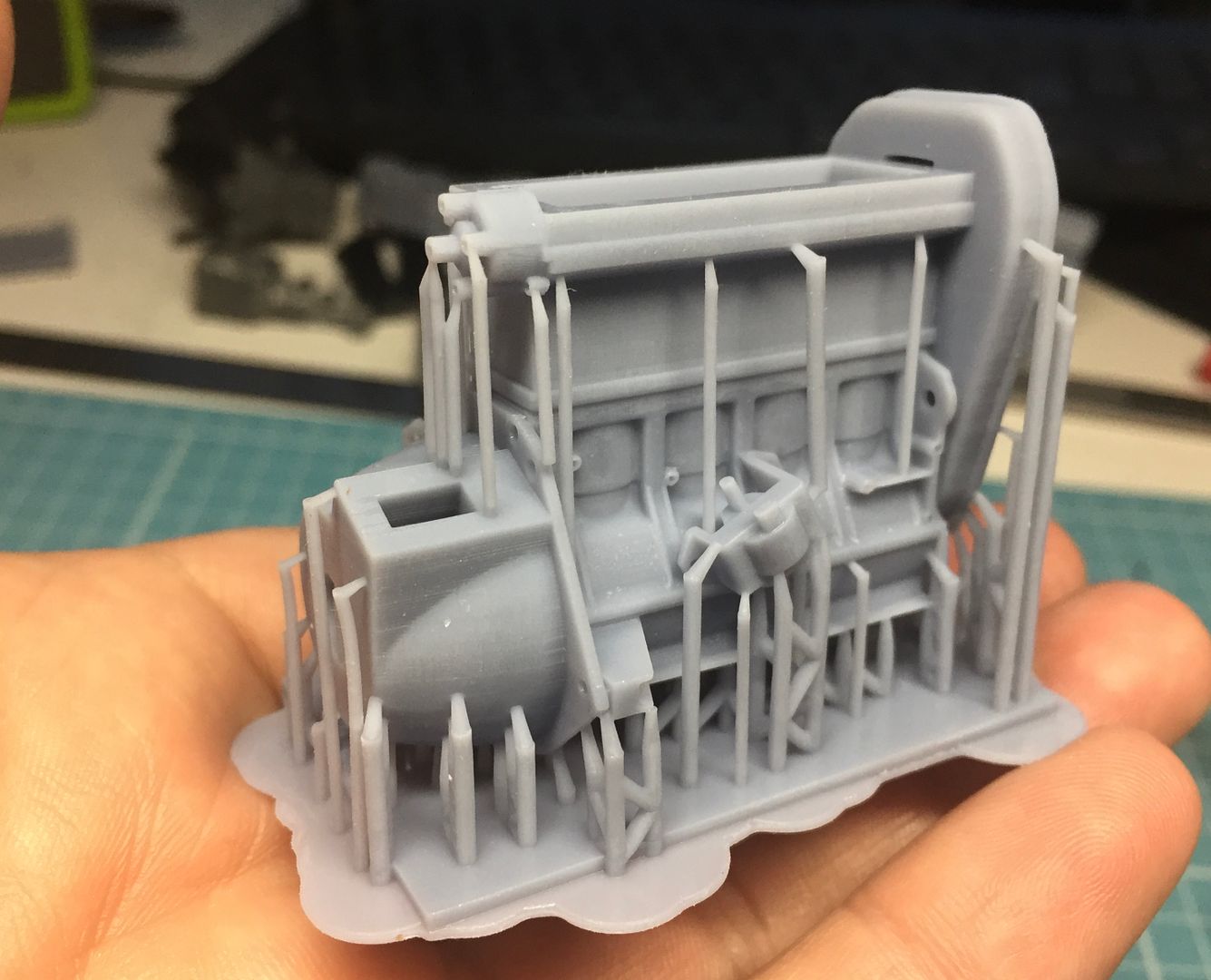
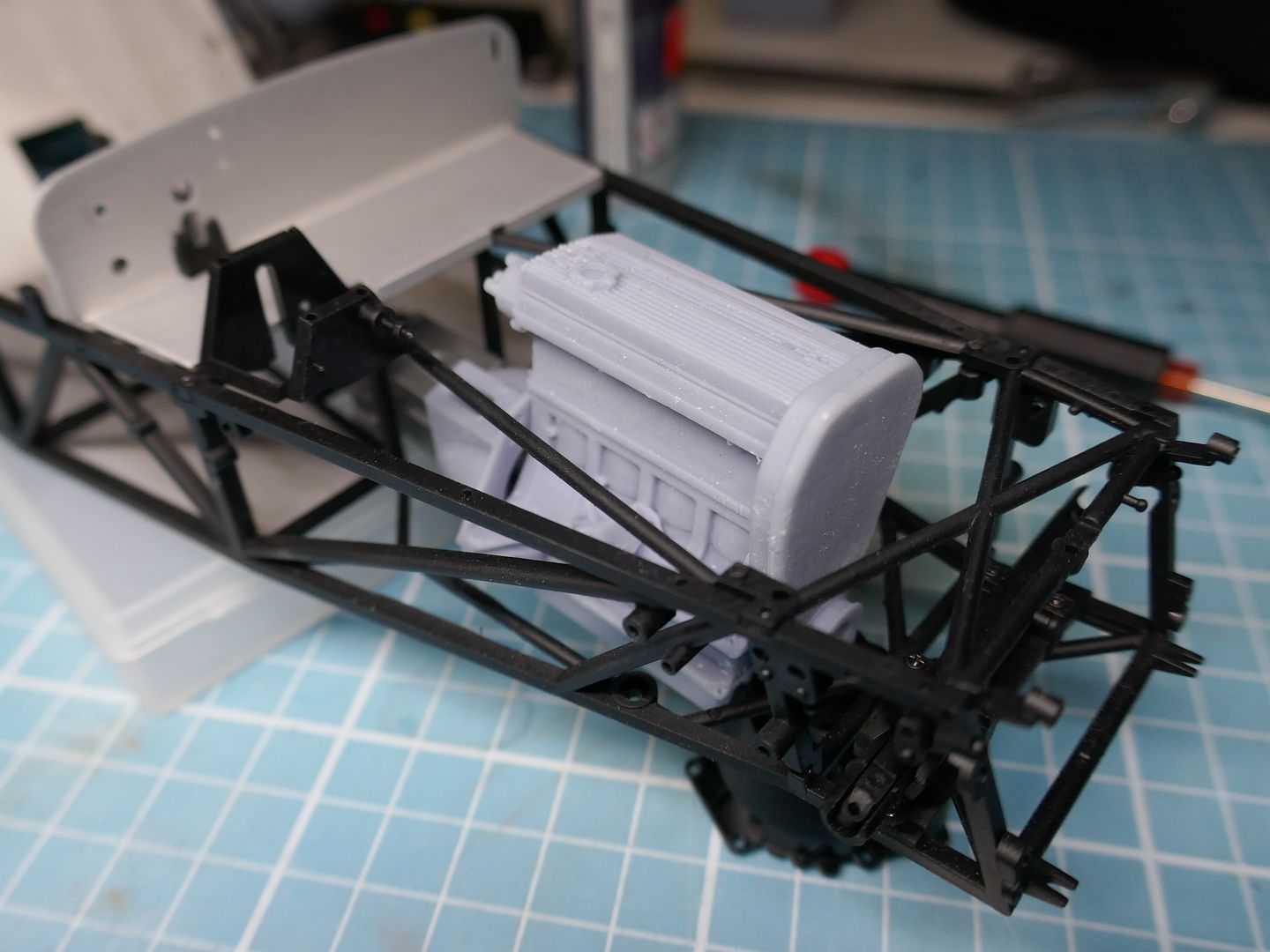
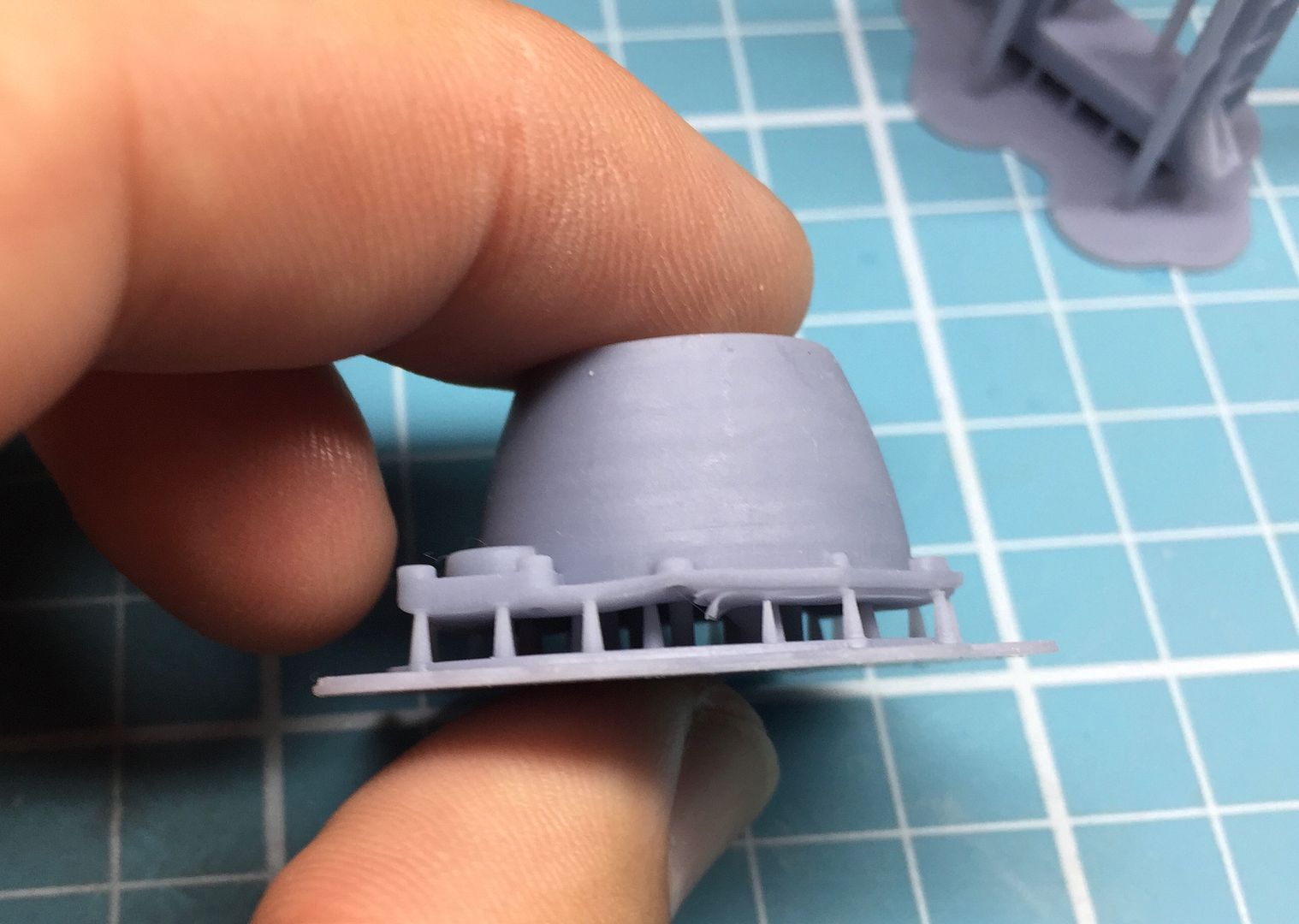
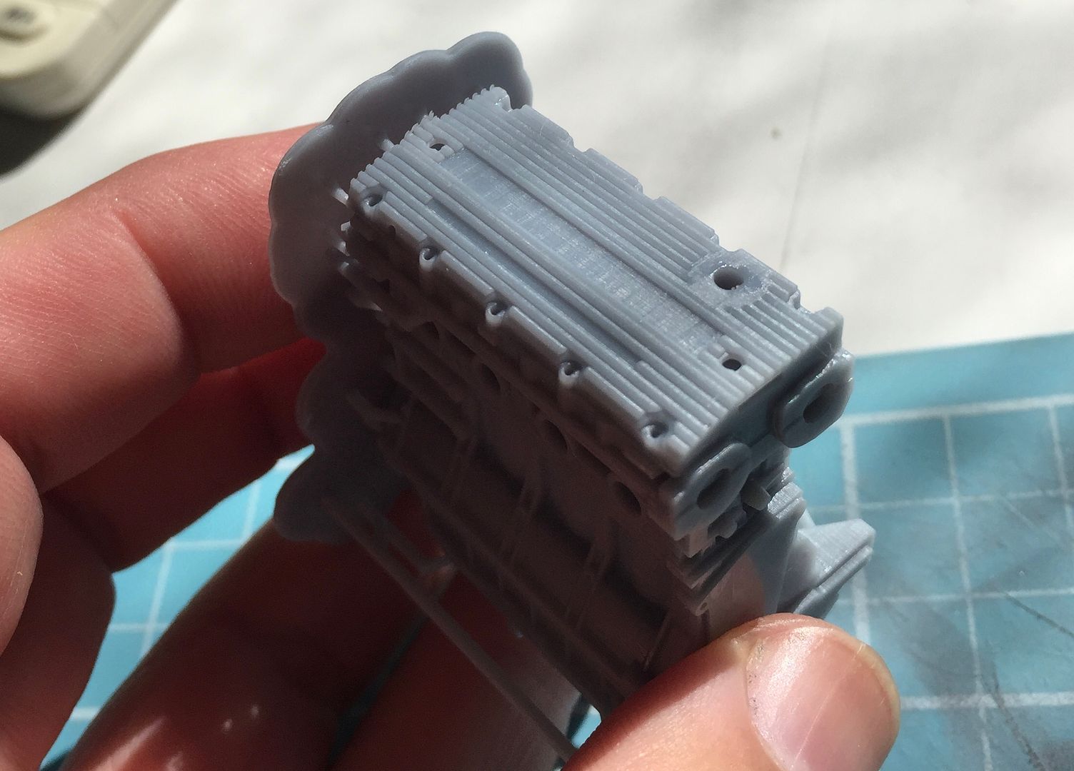
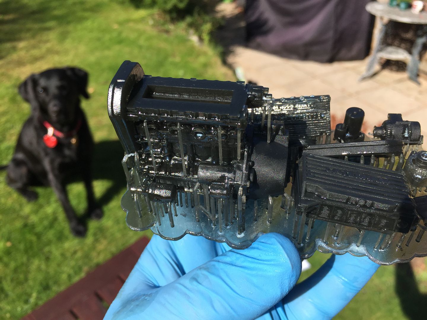
But it was getting there...
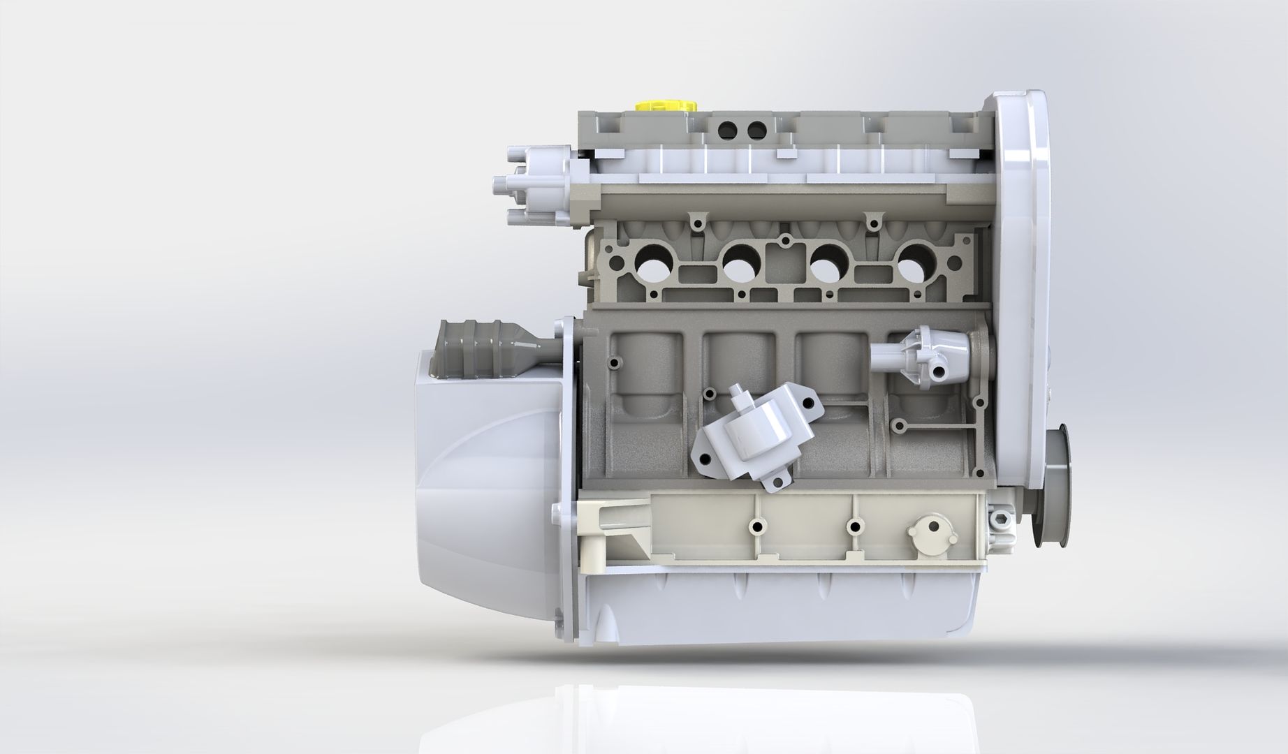
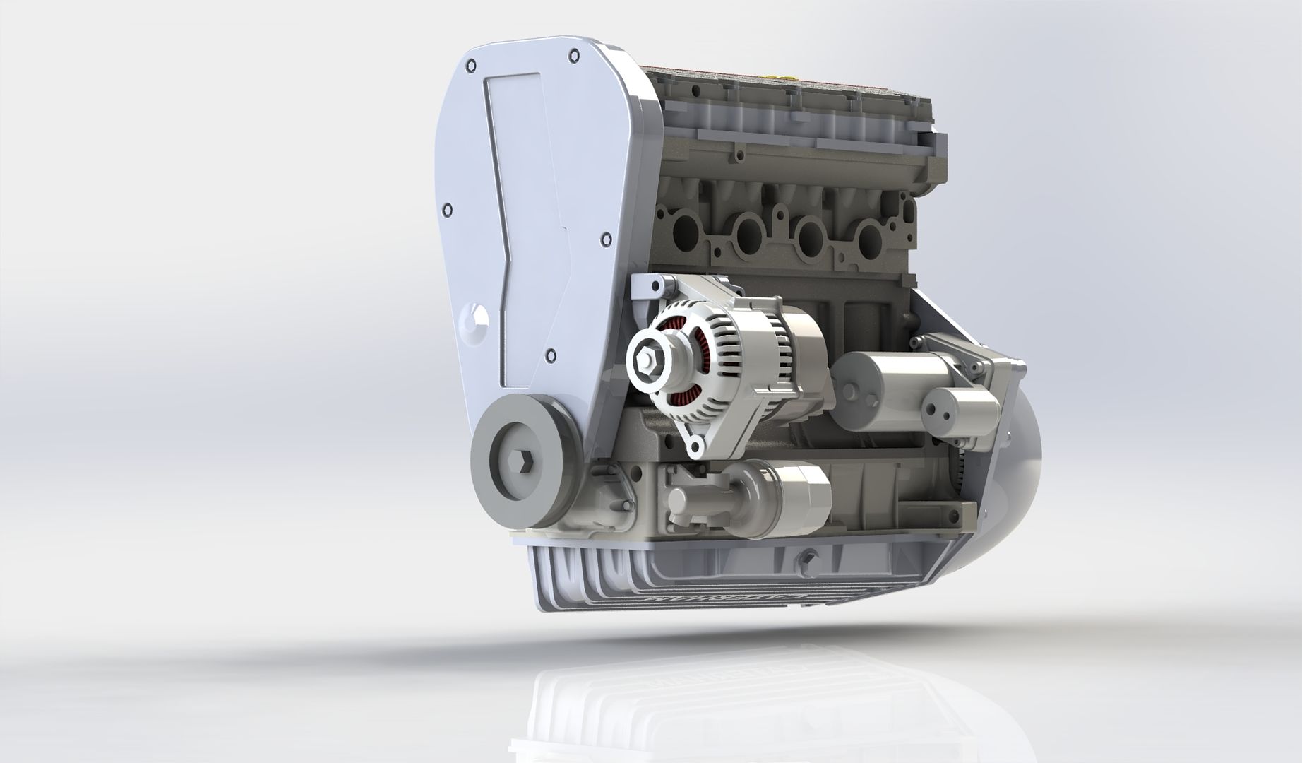
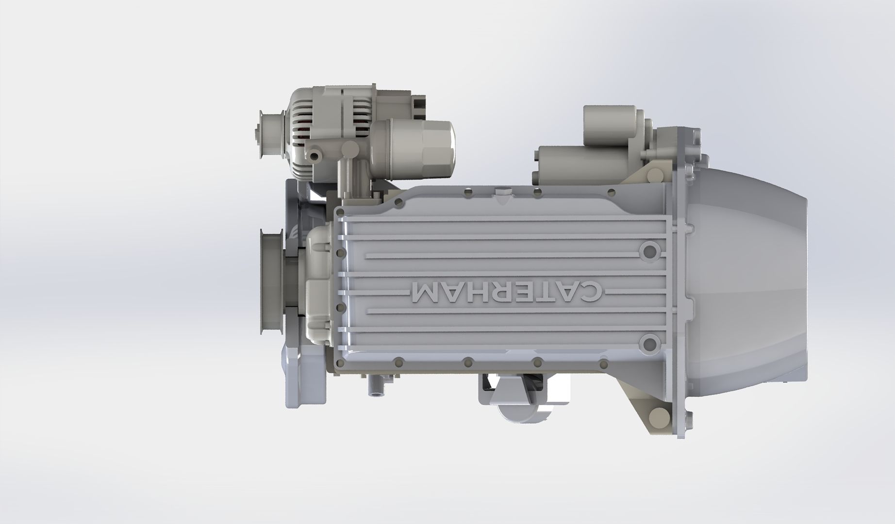
Here are some screenshots of the complete engine in CAD...
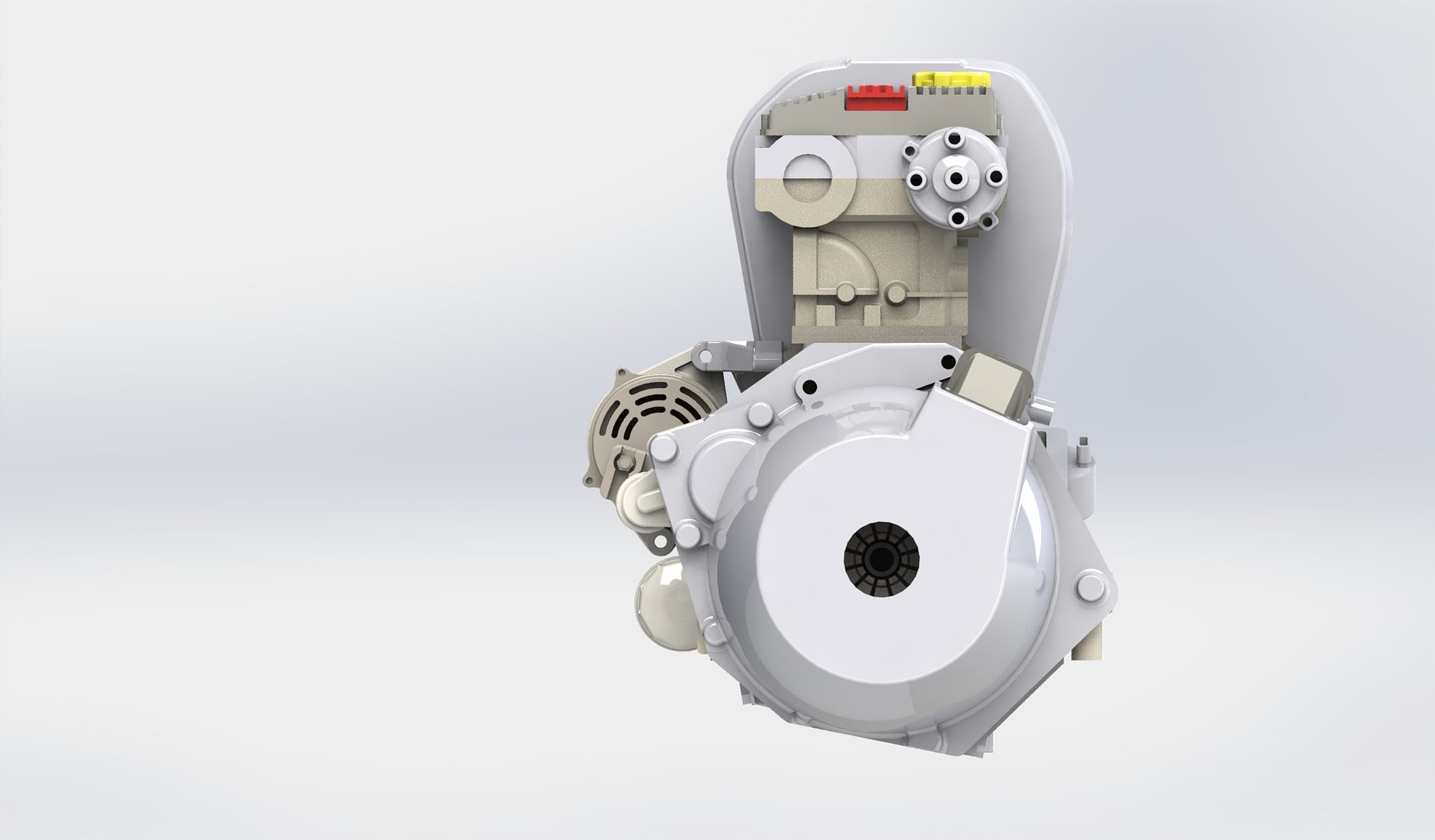
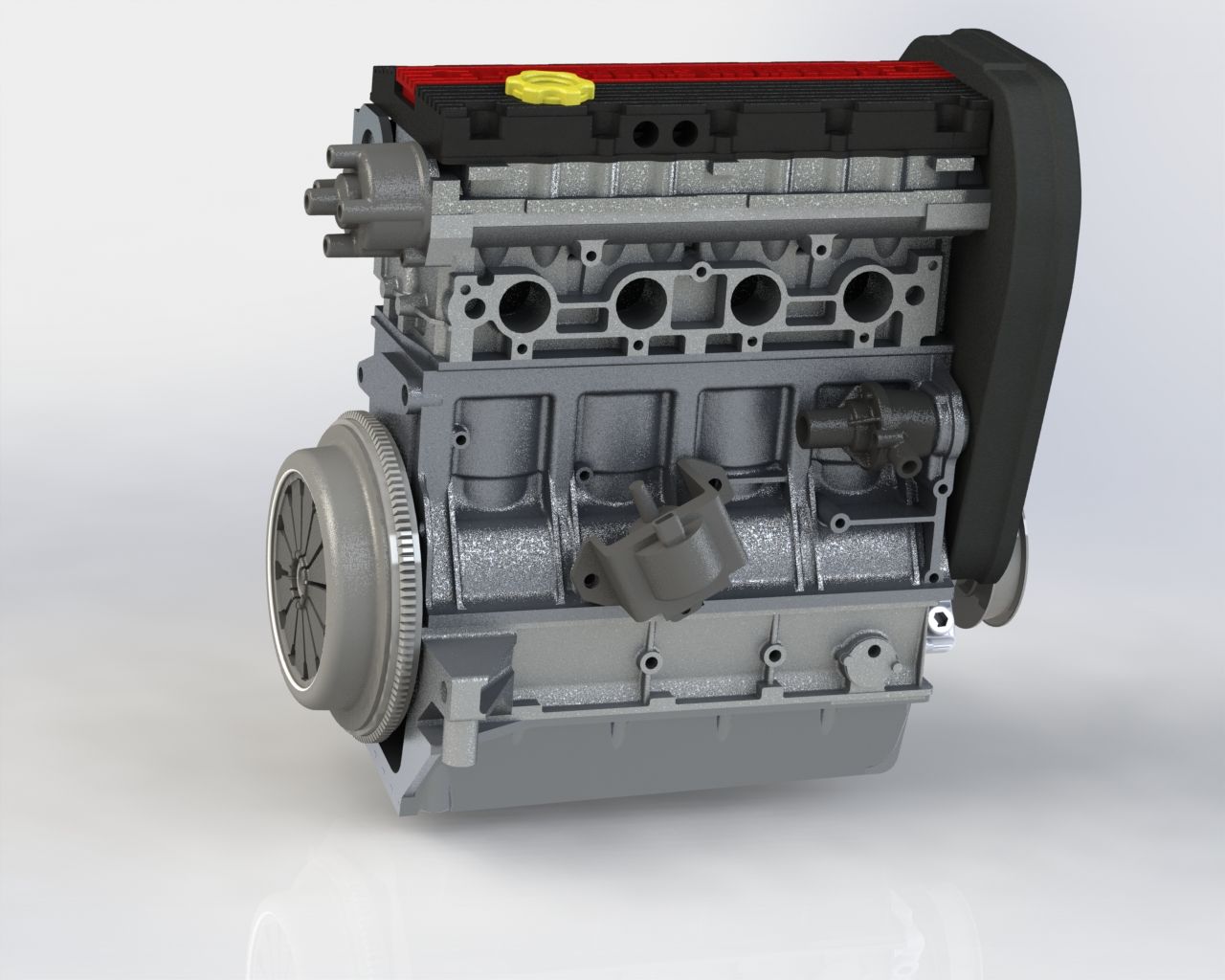
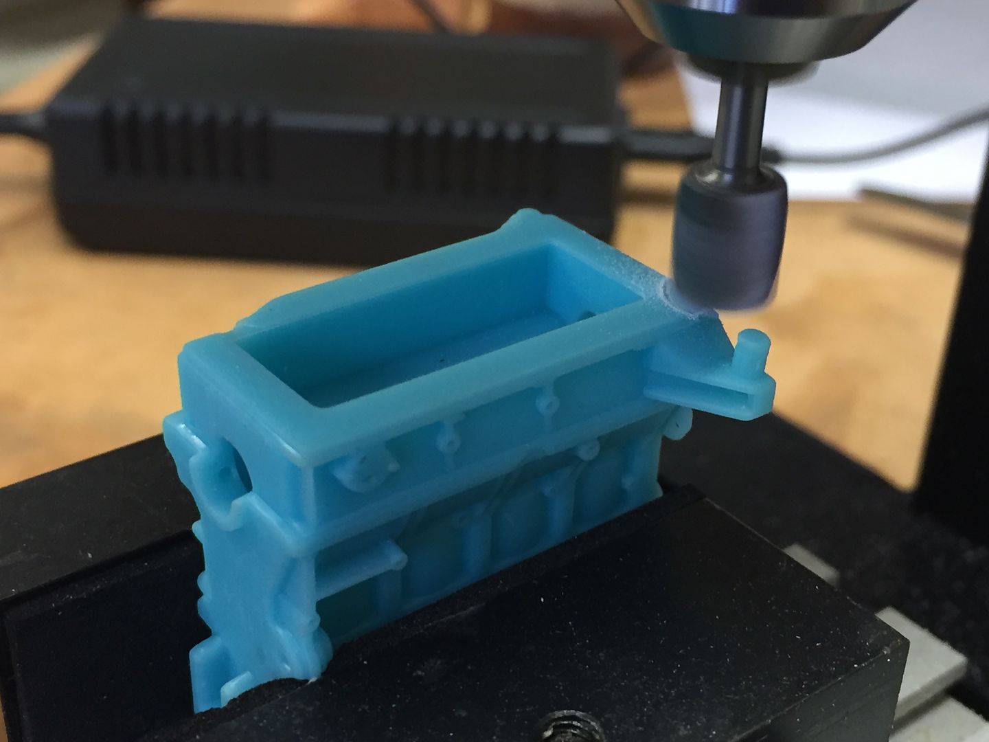
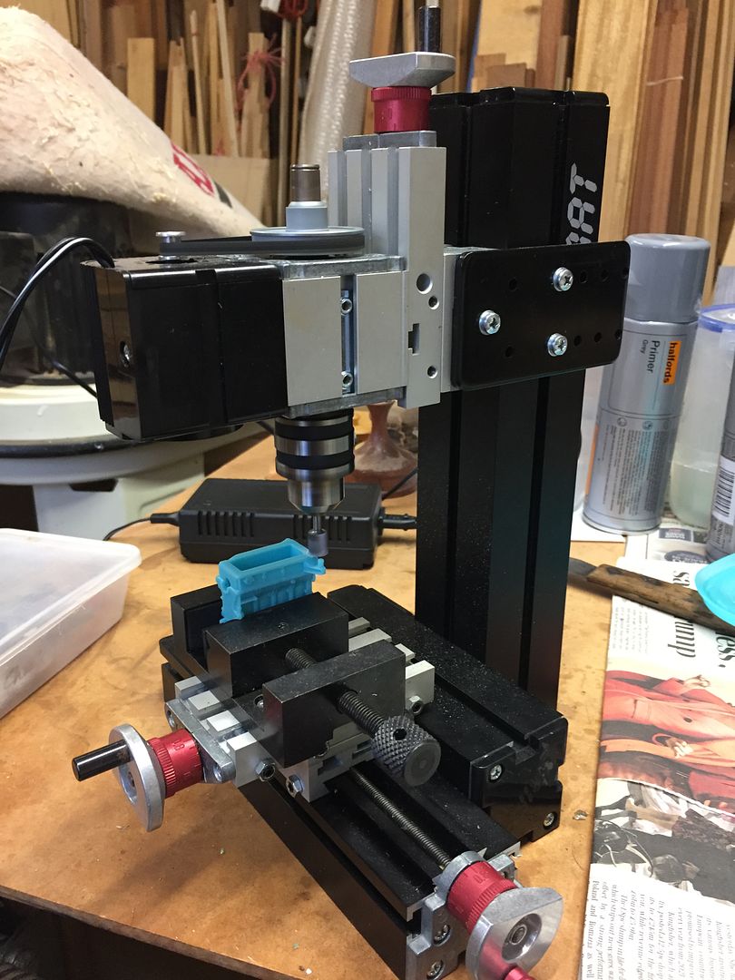
I printed a 1/8th scale block - 'just to see' - ummm - 1/8th scale model....
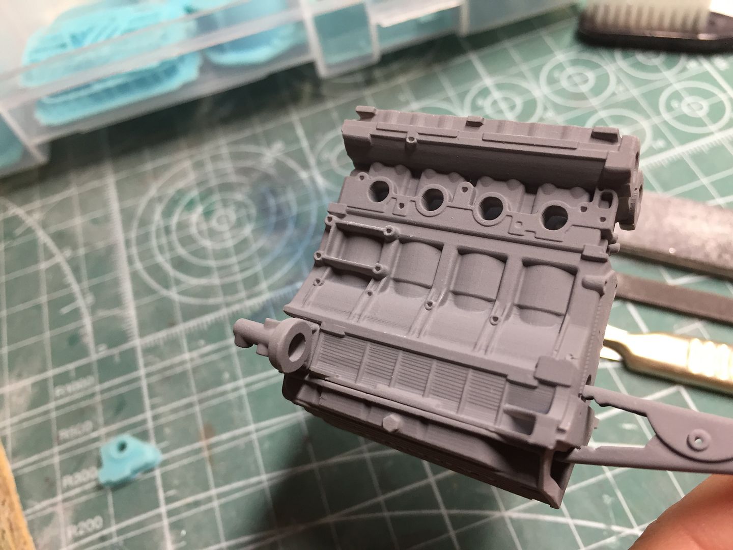
Eventually I got to the point where I was happy with the block - you can see the progression here:
Next I made the ancillaries that bolt to the block - alternator, coil, air intake, throttle, cam belt cover, pulley, starter motor etc etc etc
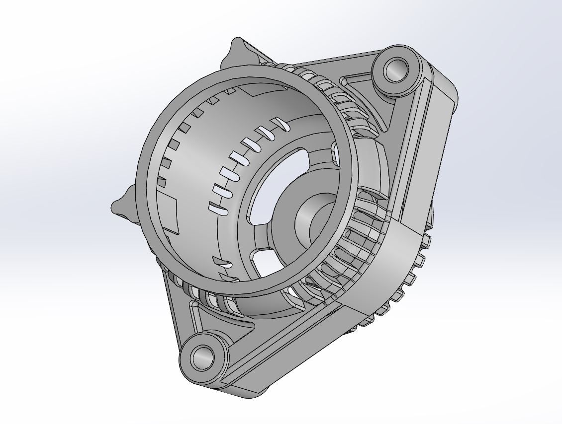
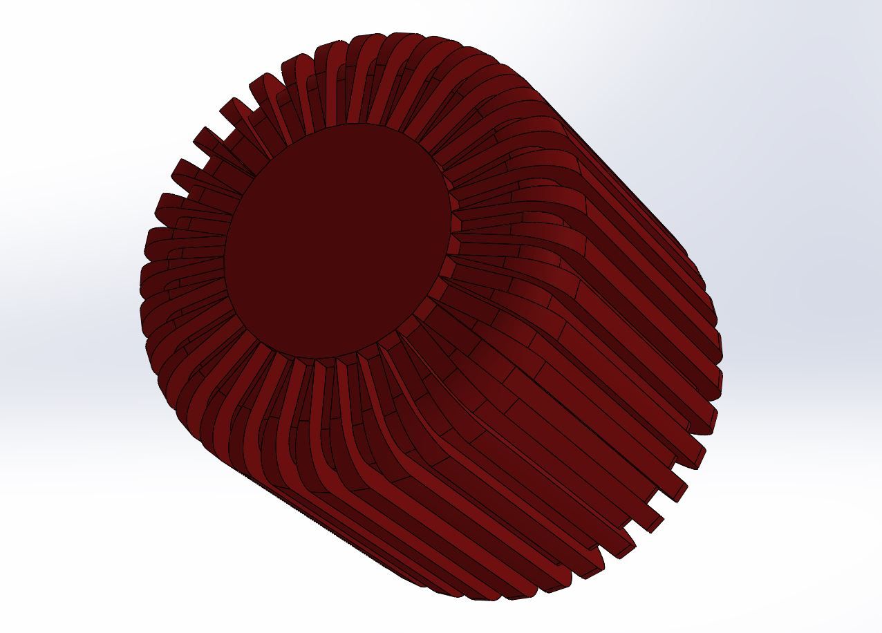
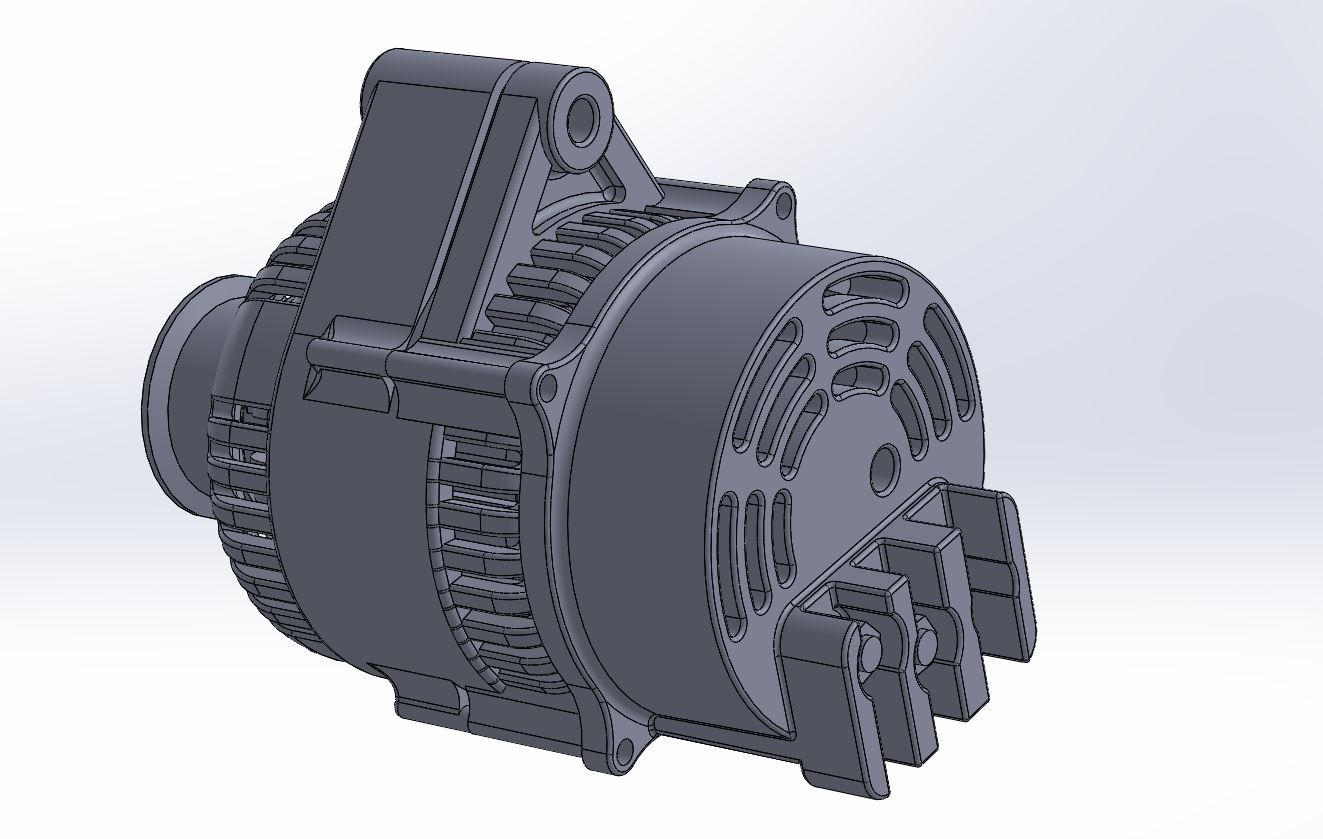
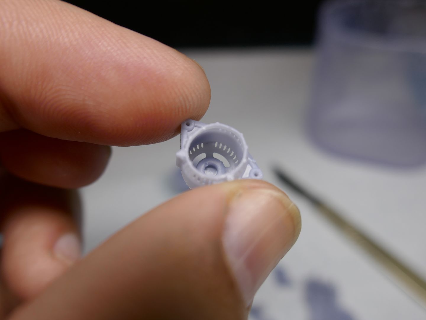
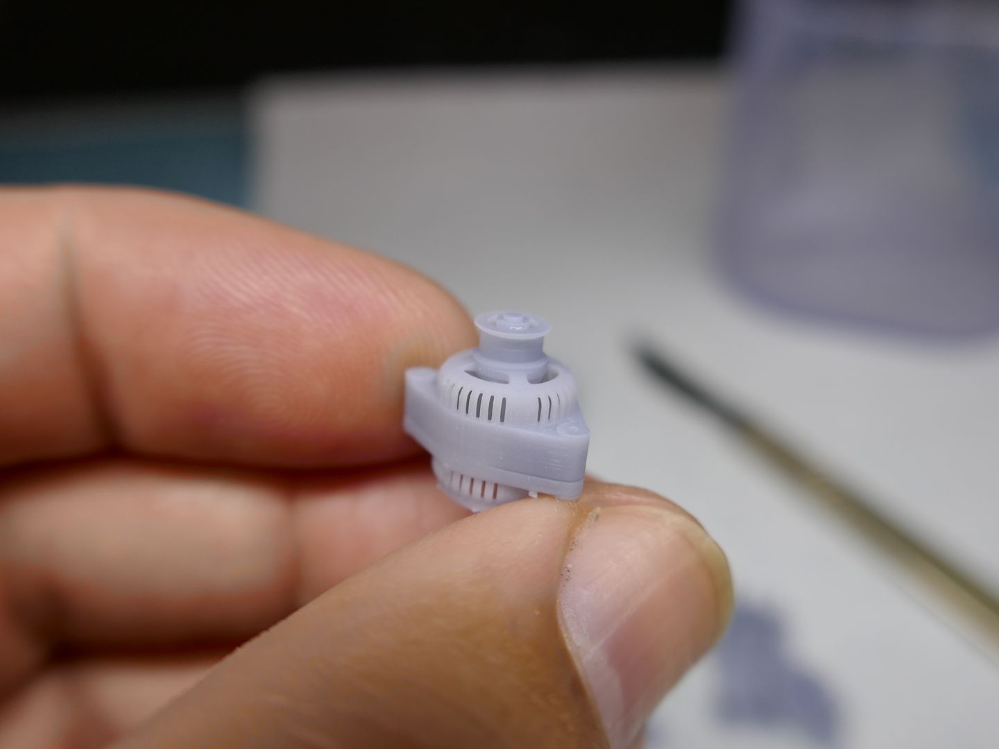
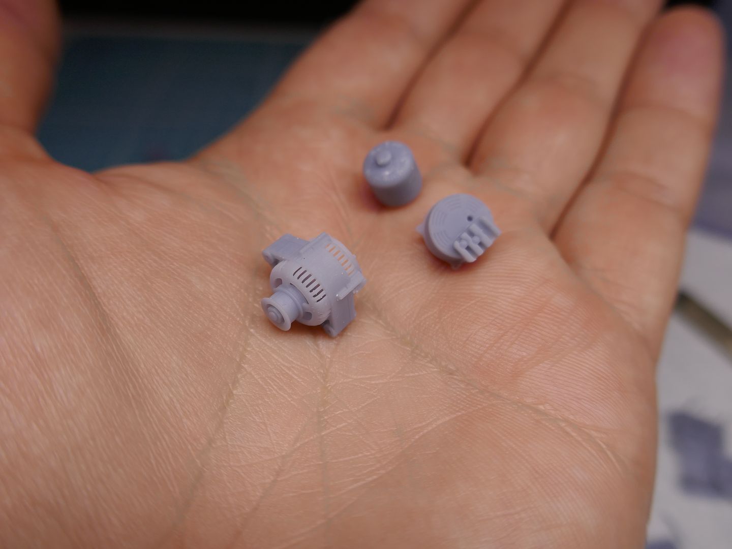
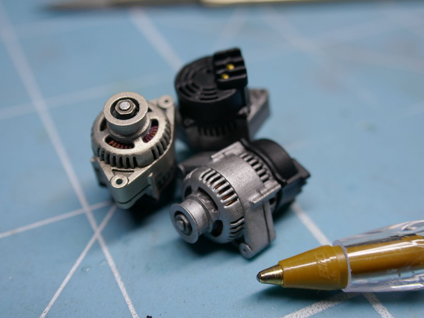
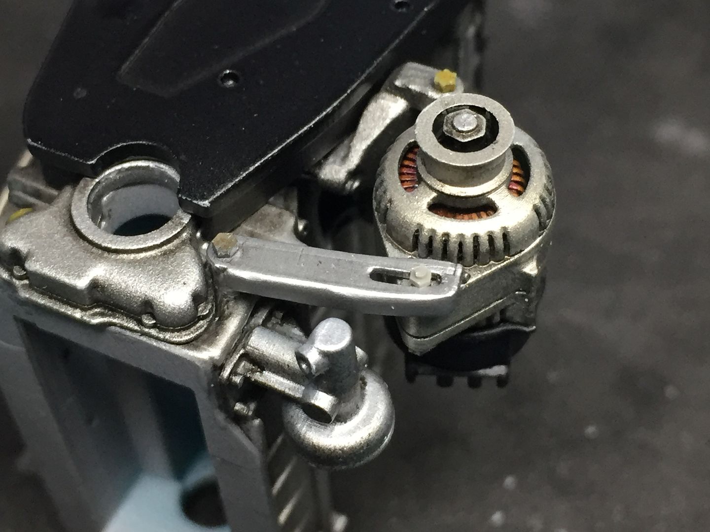
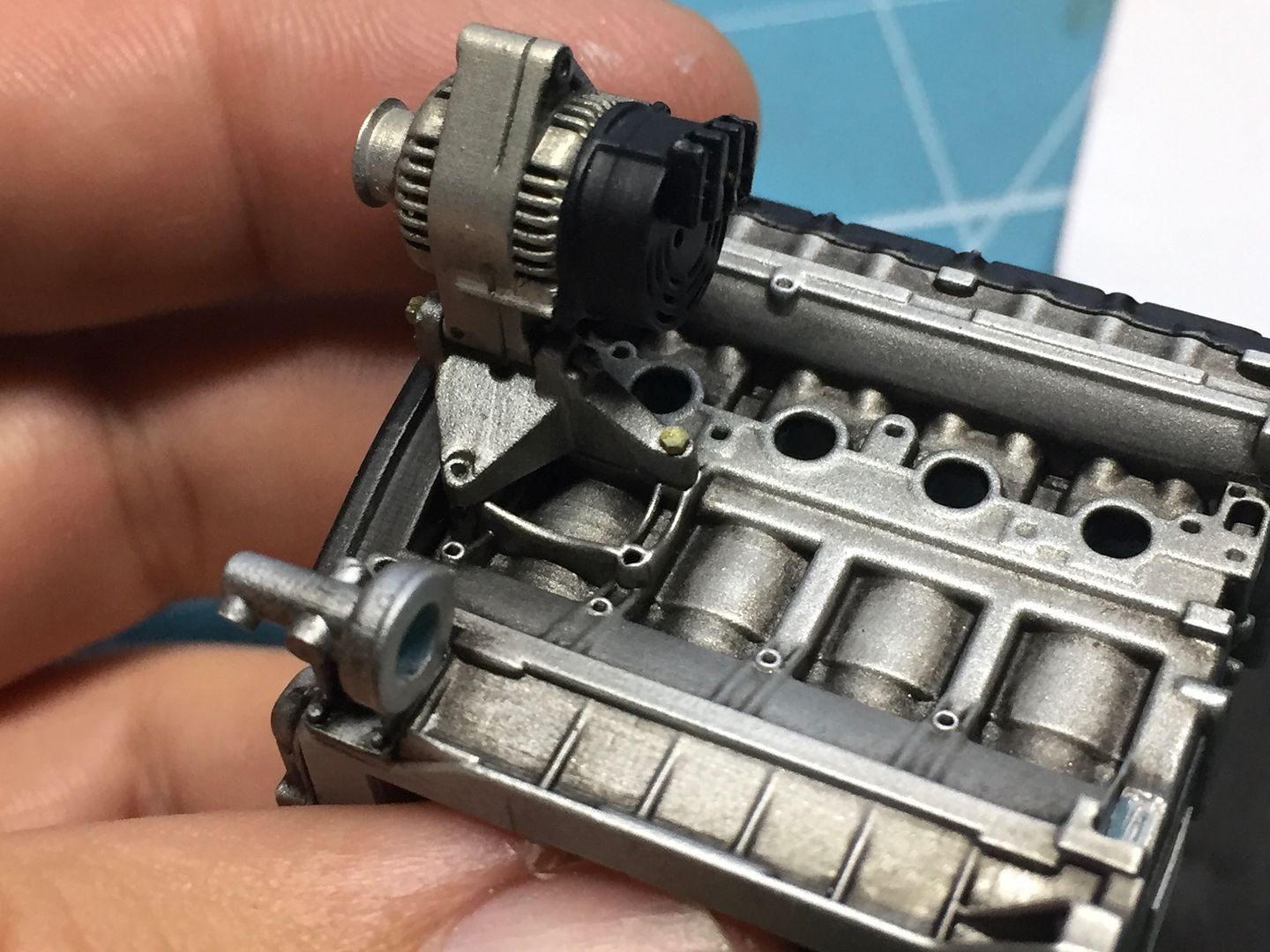
I drew up the alternator in three parts - the casting, the black plastic cap at the end and the center coil. This would make the painting easier, and allow open vents etc. I could have made the pulley separate I guess...
I added the new parts to a test block to test the fit...
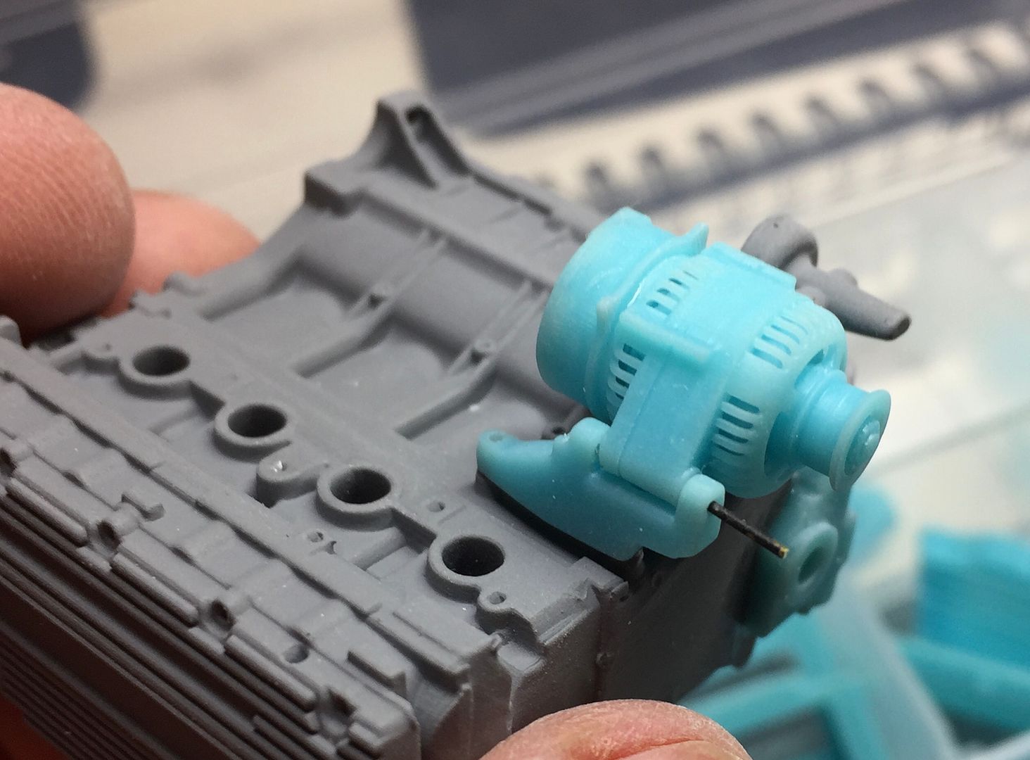
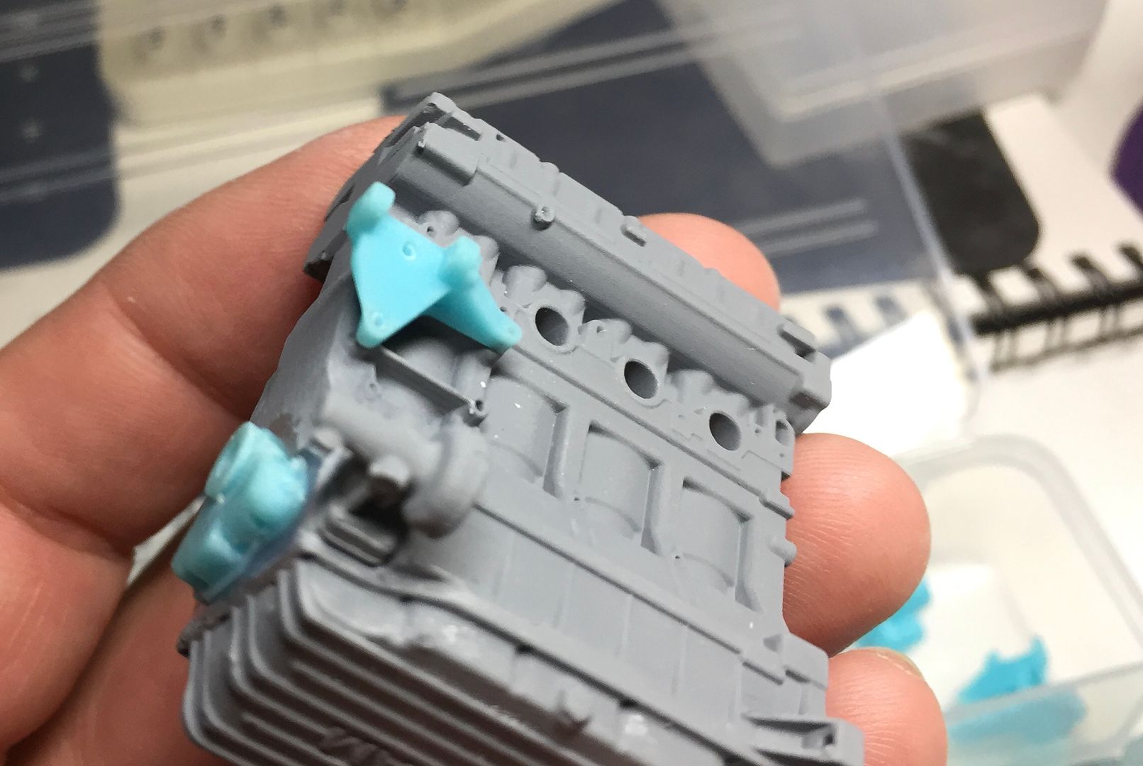
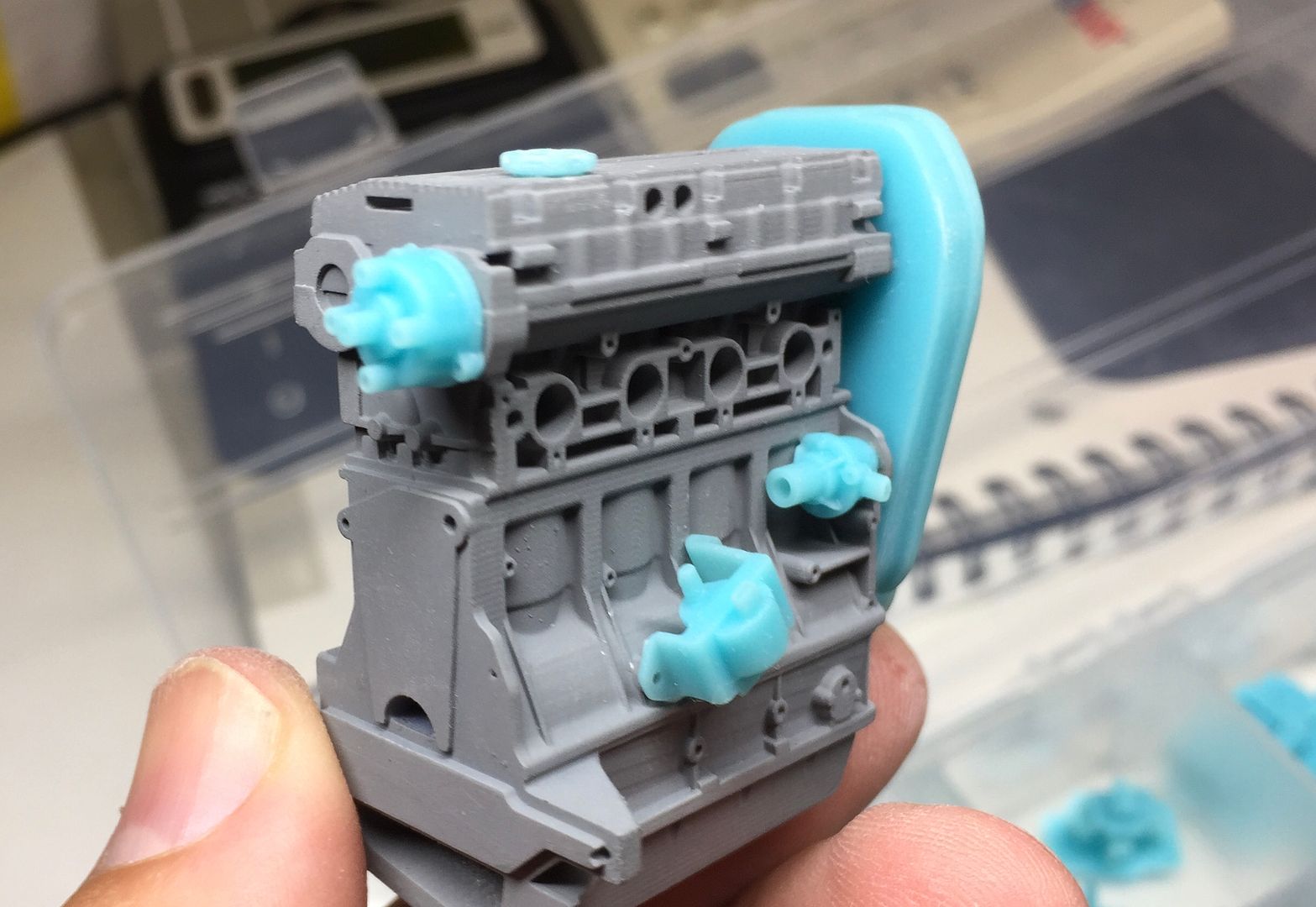
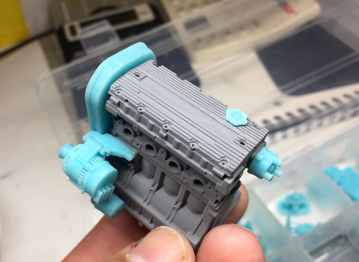
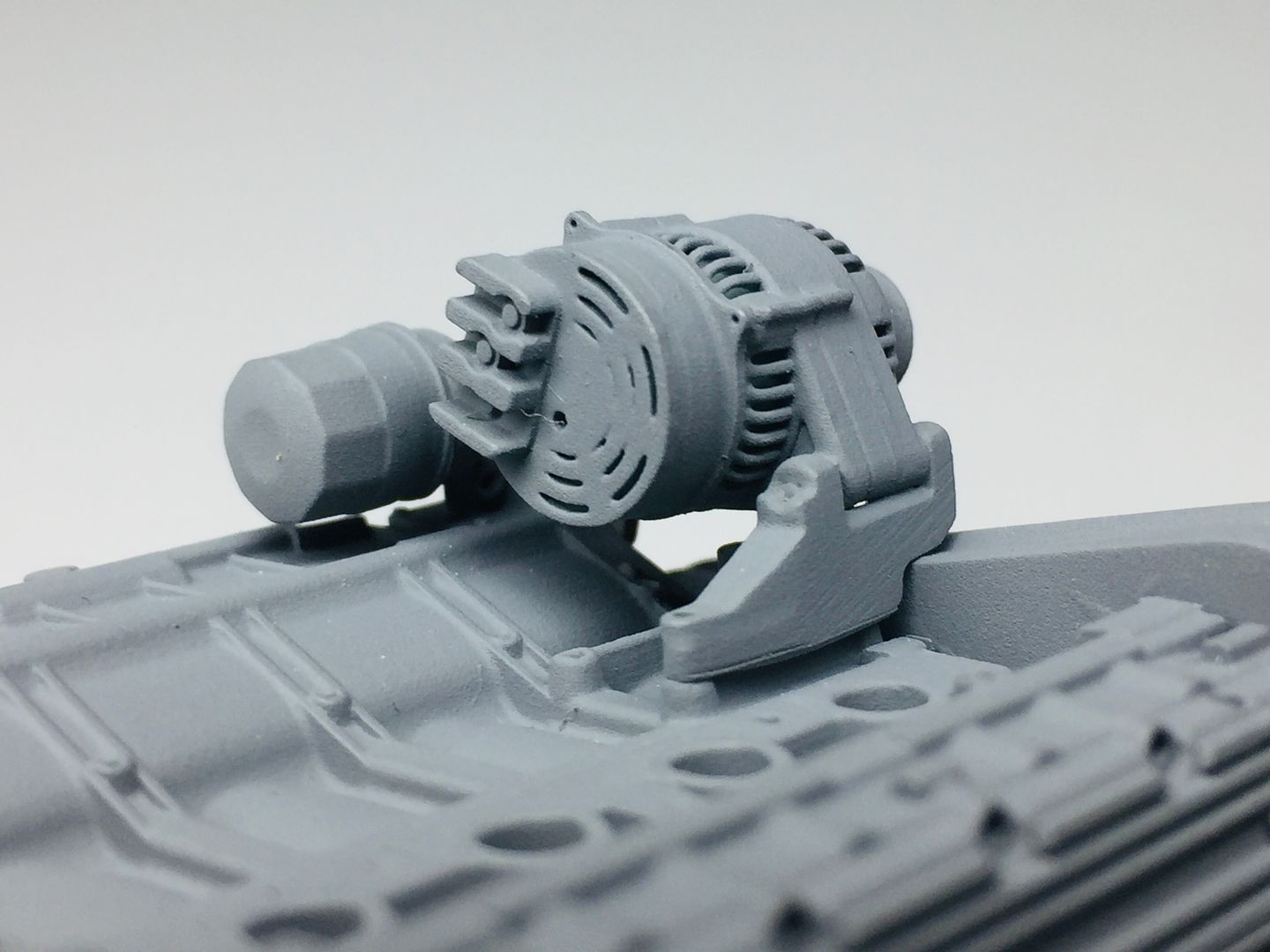
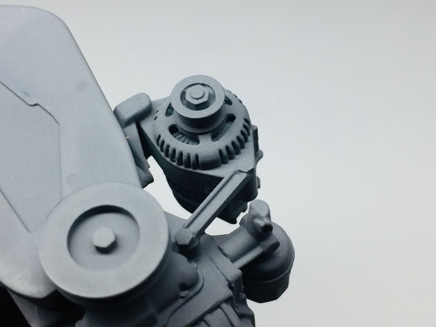
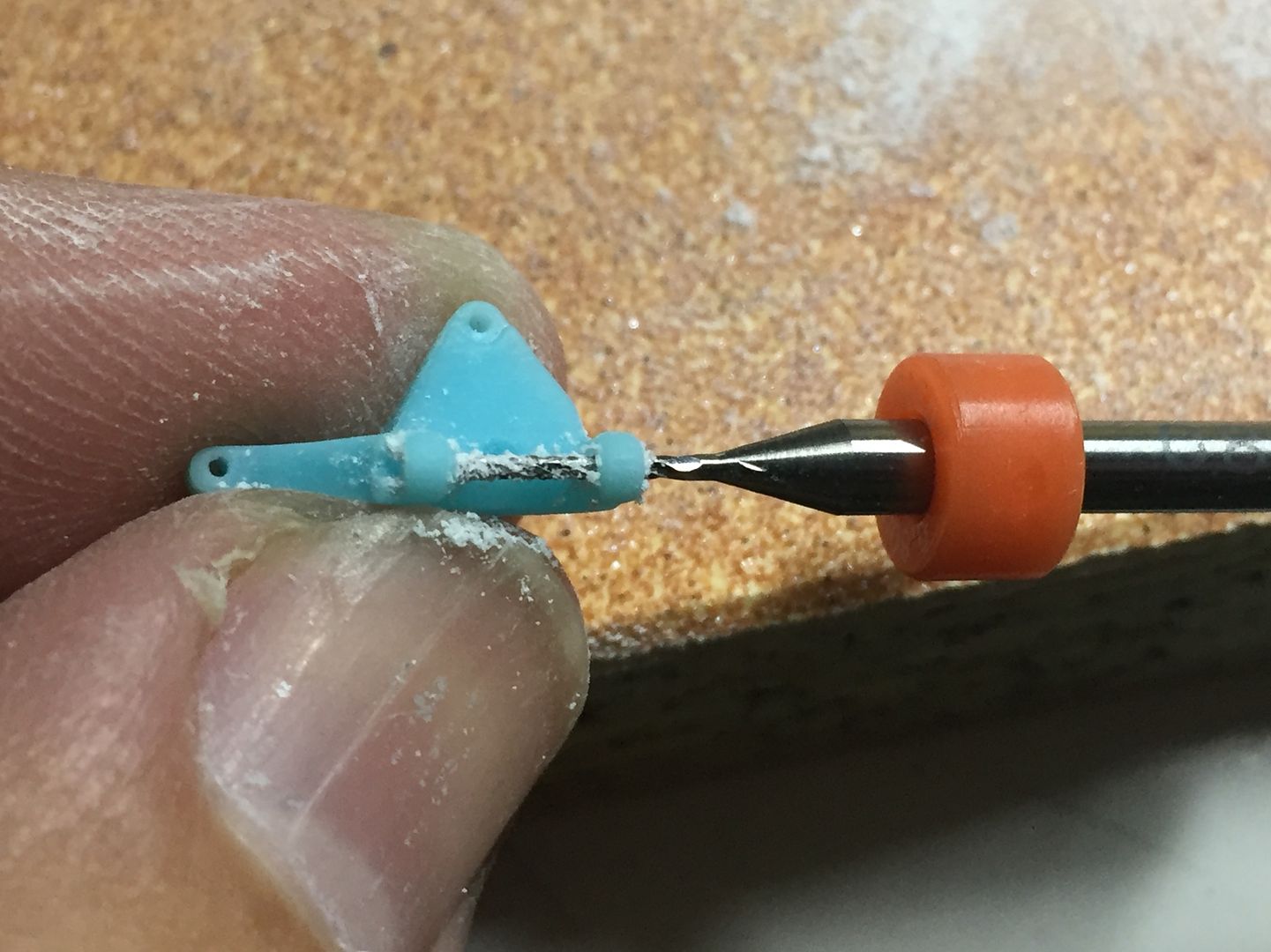
Drilling the alternator bracket...
There comes a point where you think 'what am I doing modelling this...?!' - in this case, it was when i was drawing up the crank sensor...
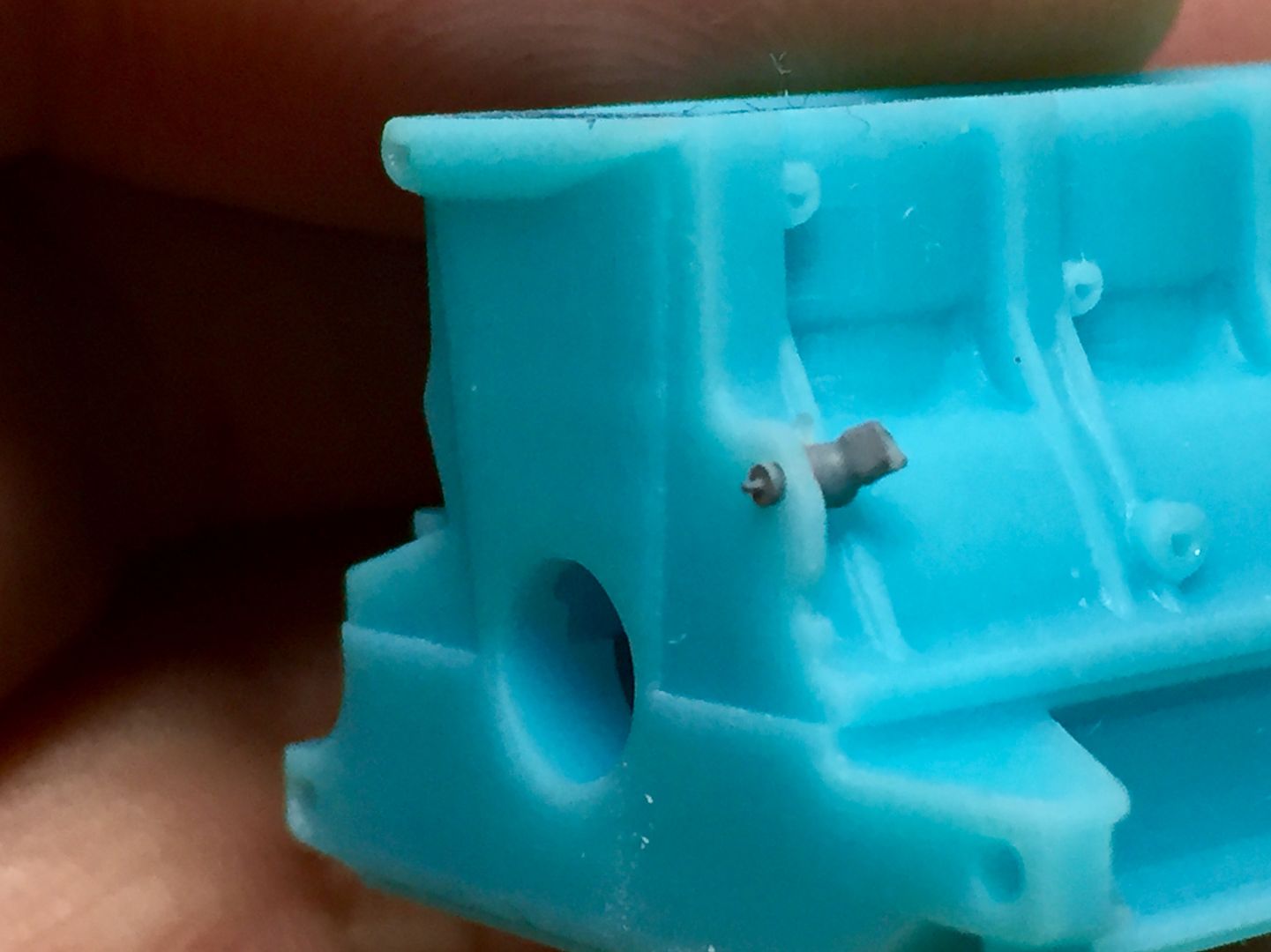
By far the smallest part I have printed..
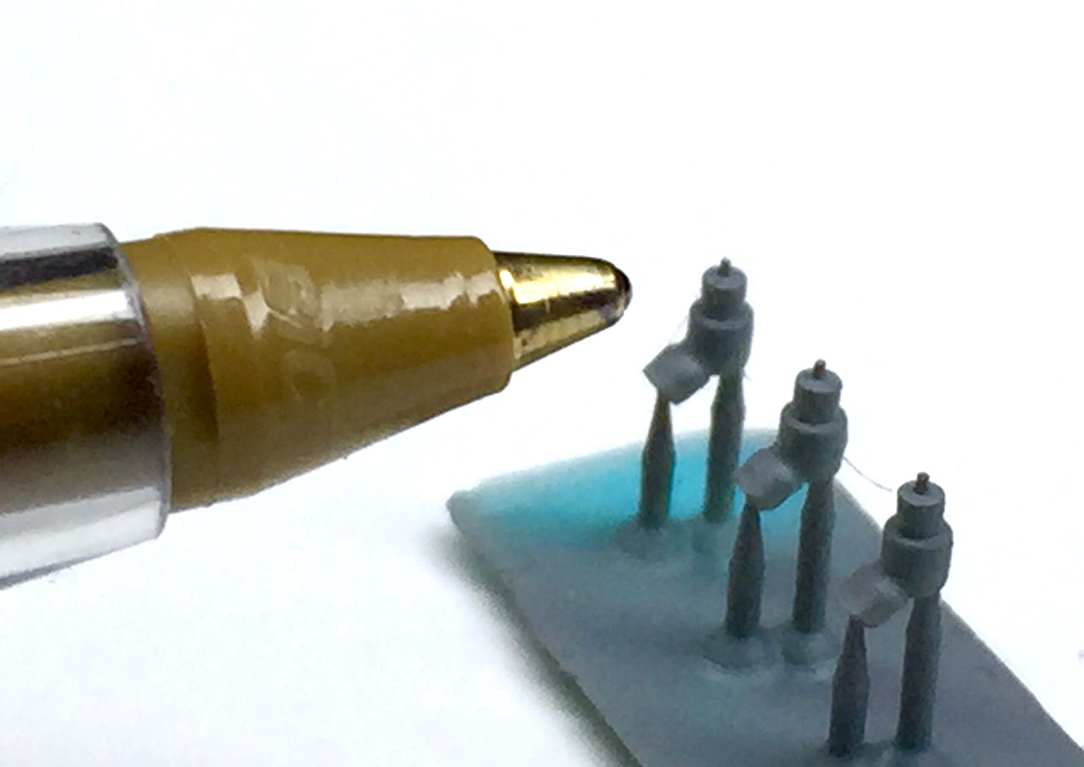
(get used to that pen)
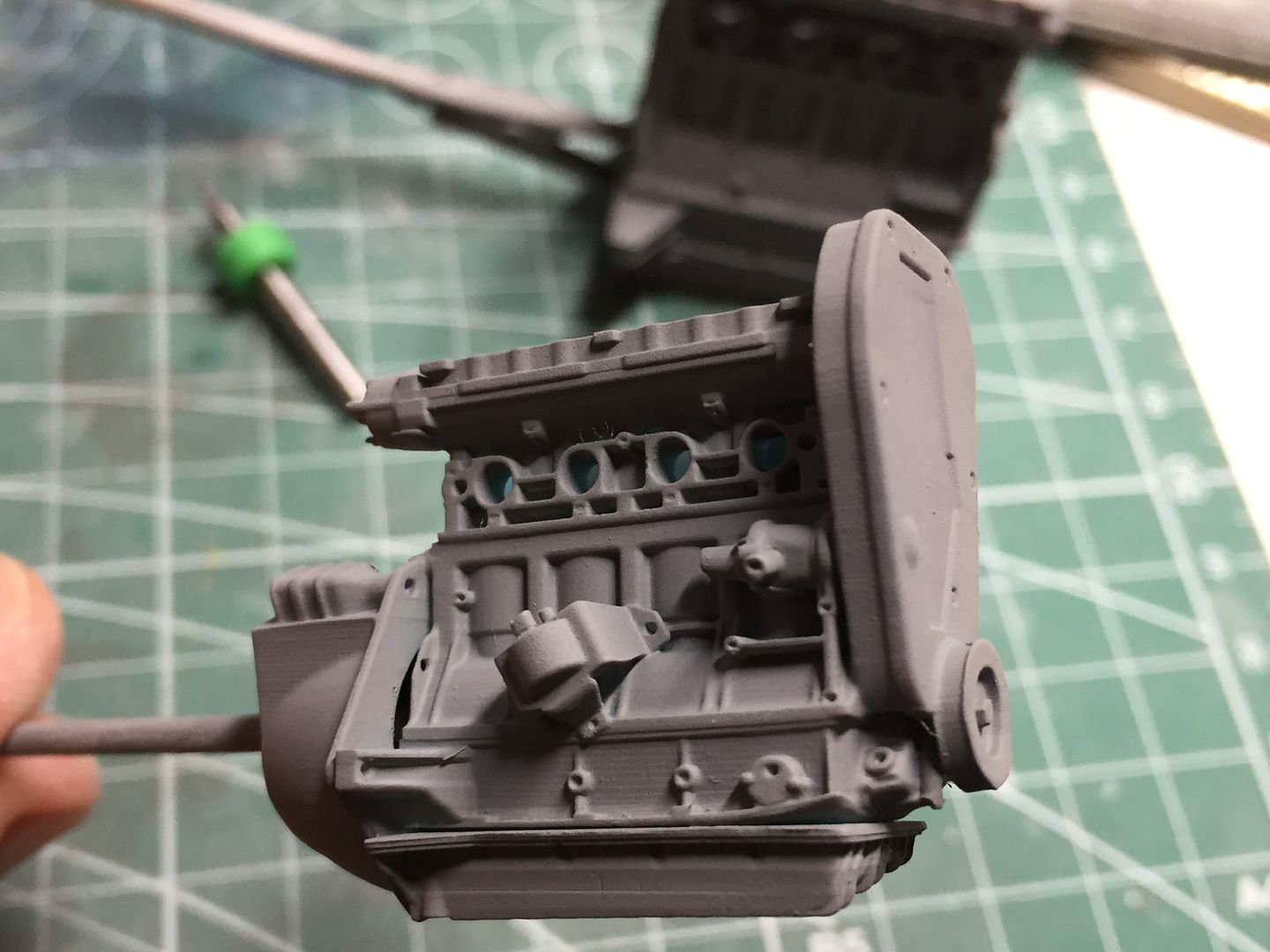
Adding paint really transforms everything!
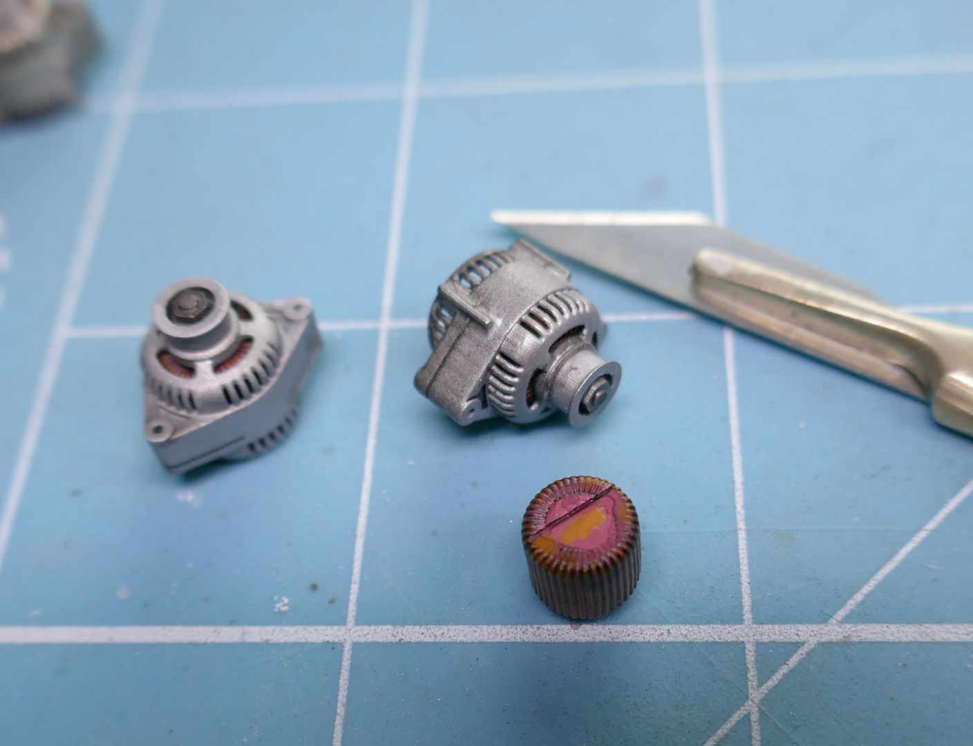
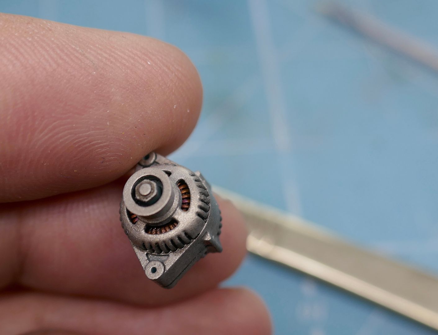
That crank sensor needed a flywheel - which needed a clutch (which would be hidden by the bellhousing, visible in only a few gaps - but what the hell - in for a penny, in for a pound!!
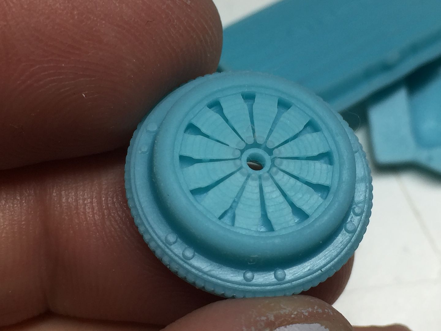
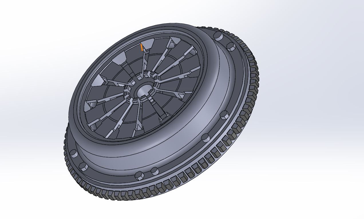
Forgot the gloves...
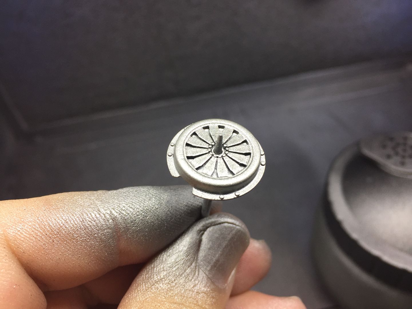
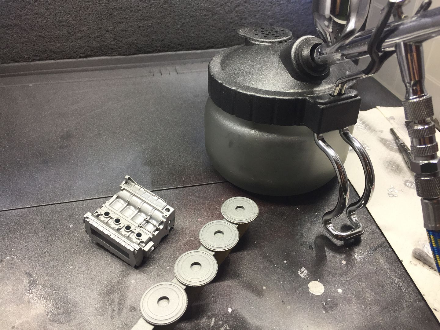
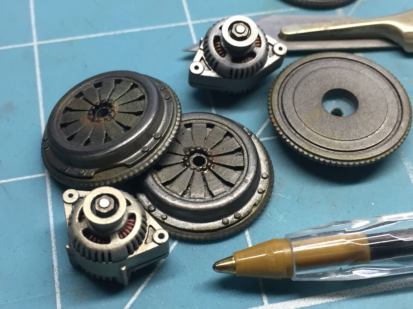
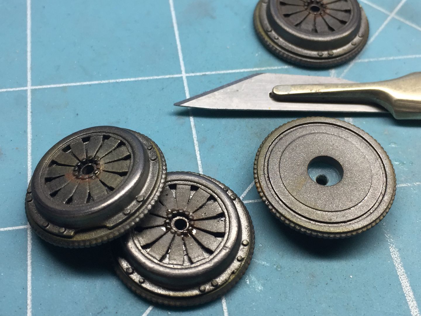
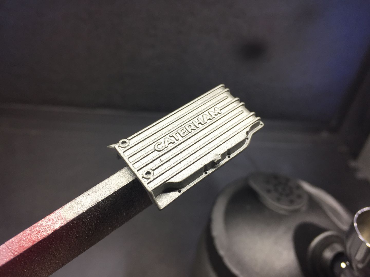
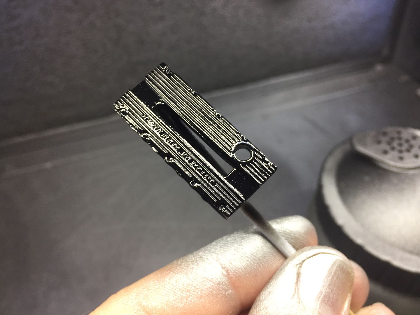
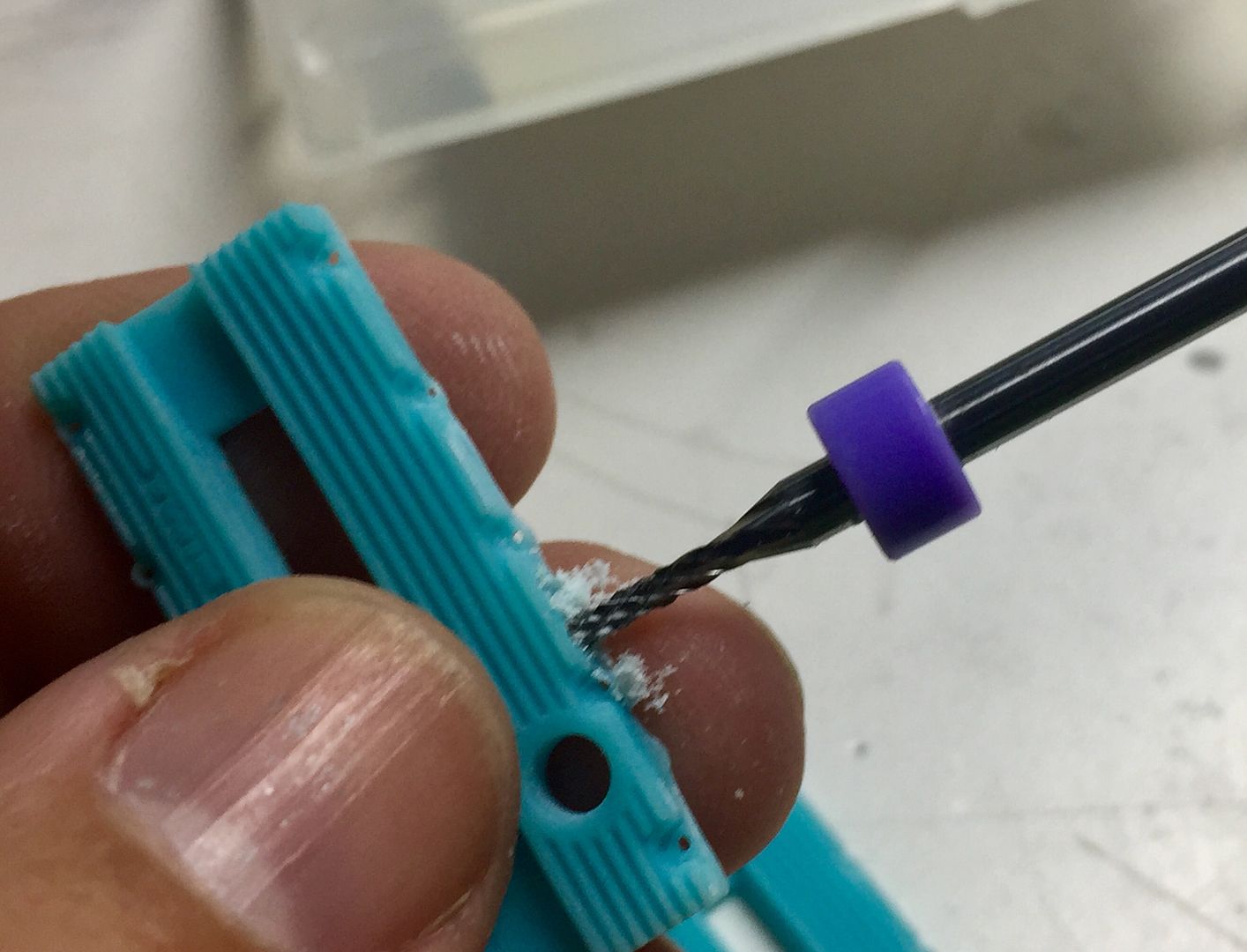
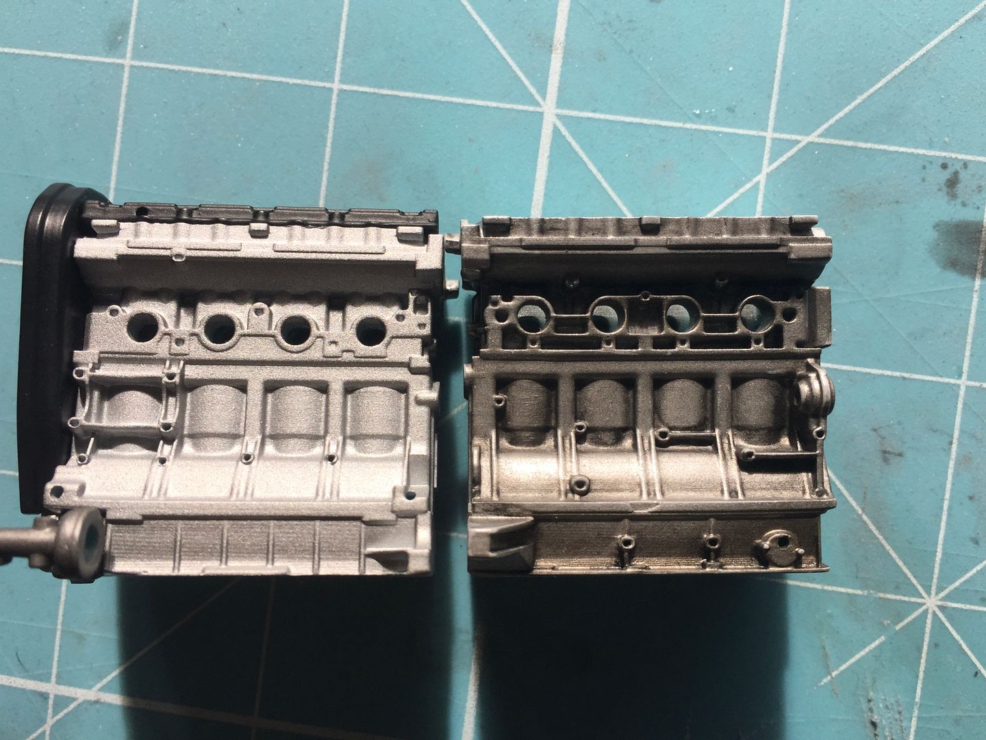
Testing silvers for the block...
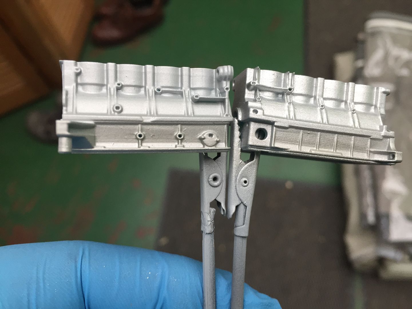
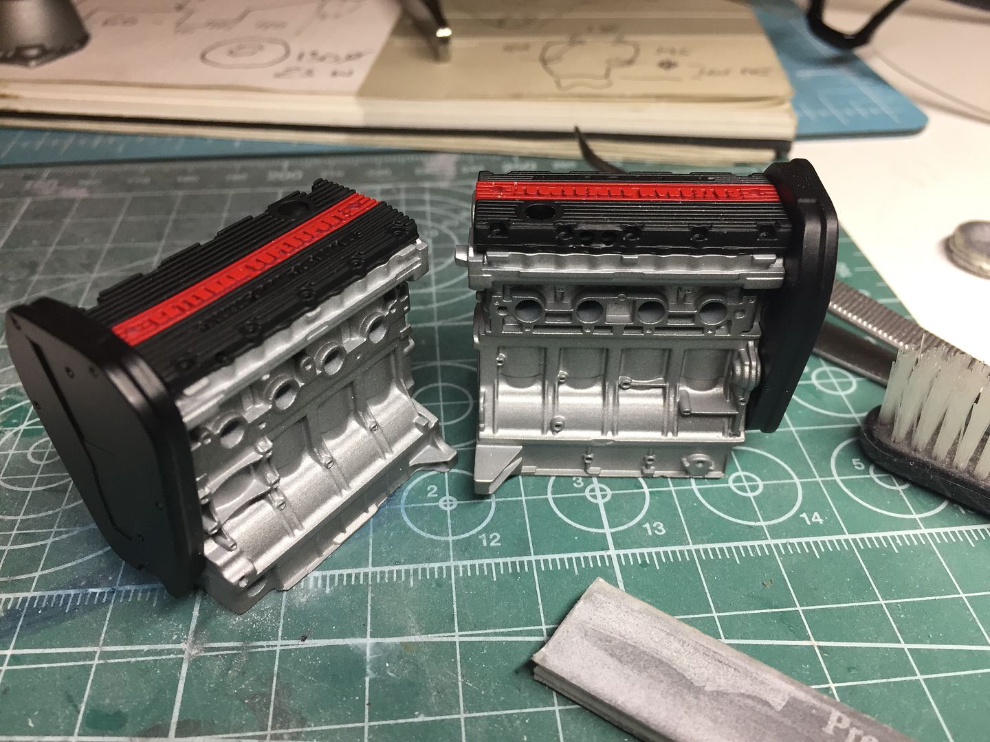
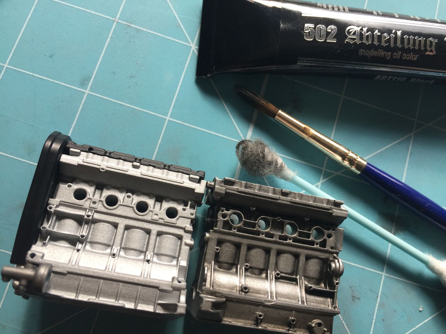
I used an oil wash to make it look grubby with.....oil!
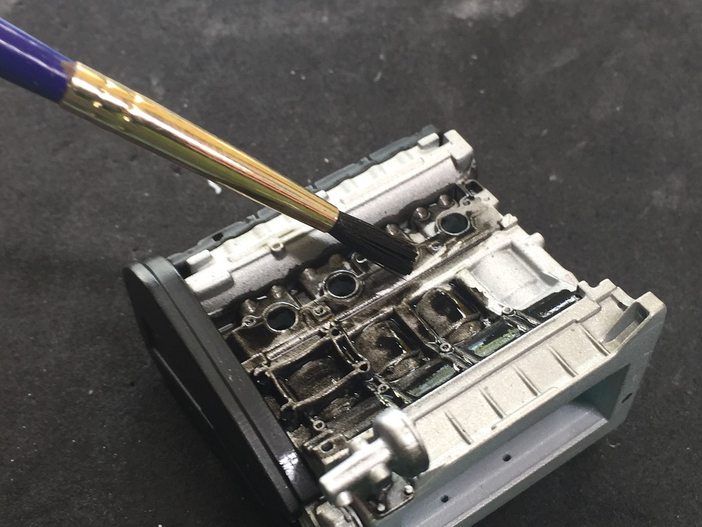
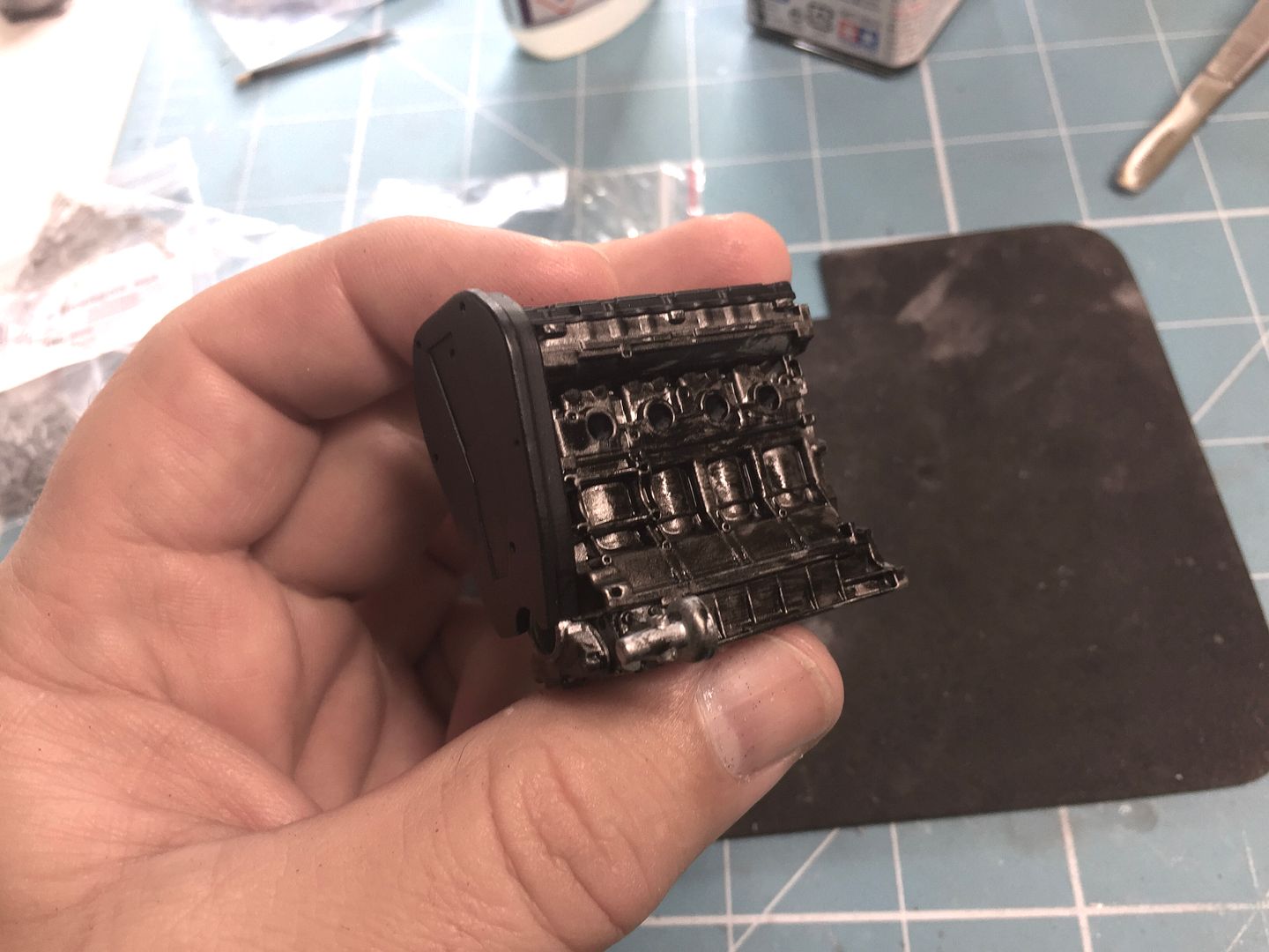
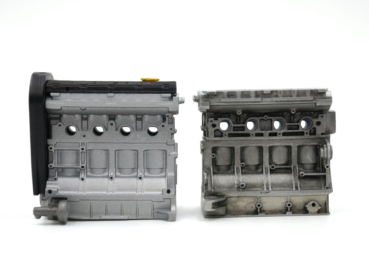
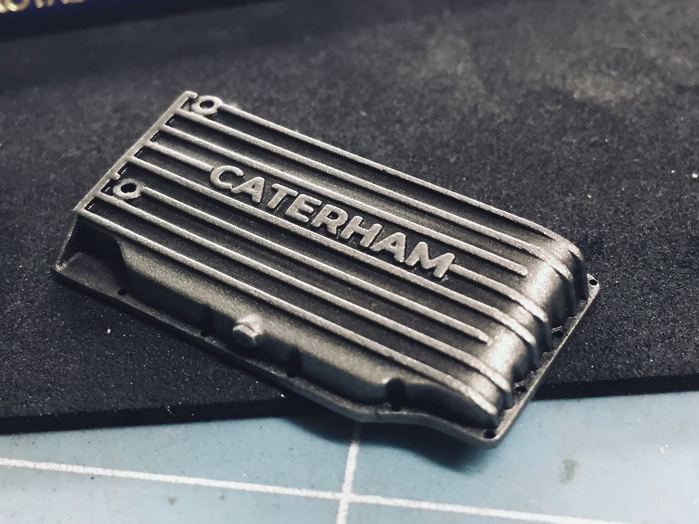
..and started to paint and add the other parts - here is the coil being bolted in place...
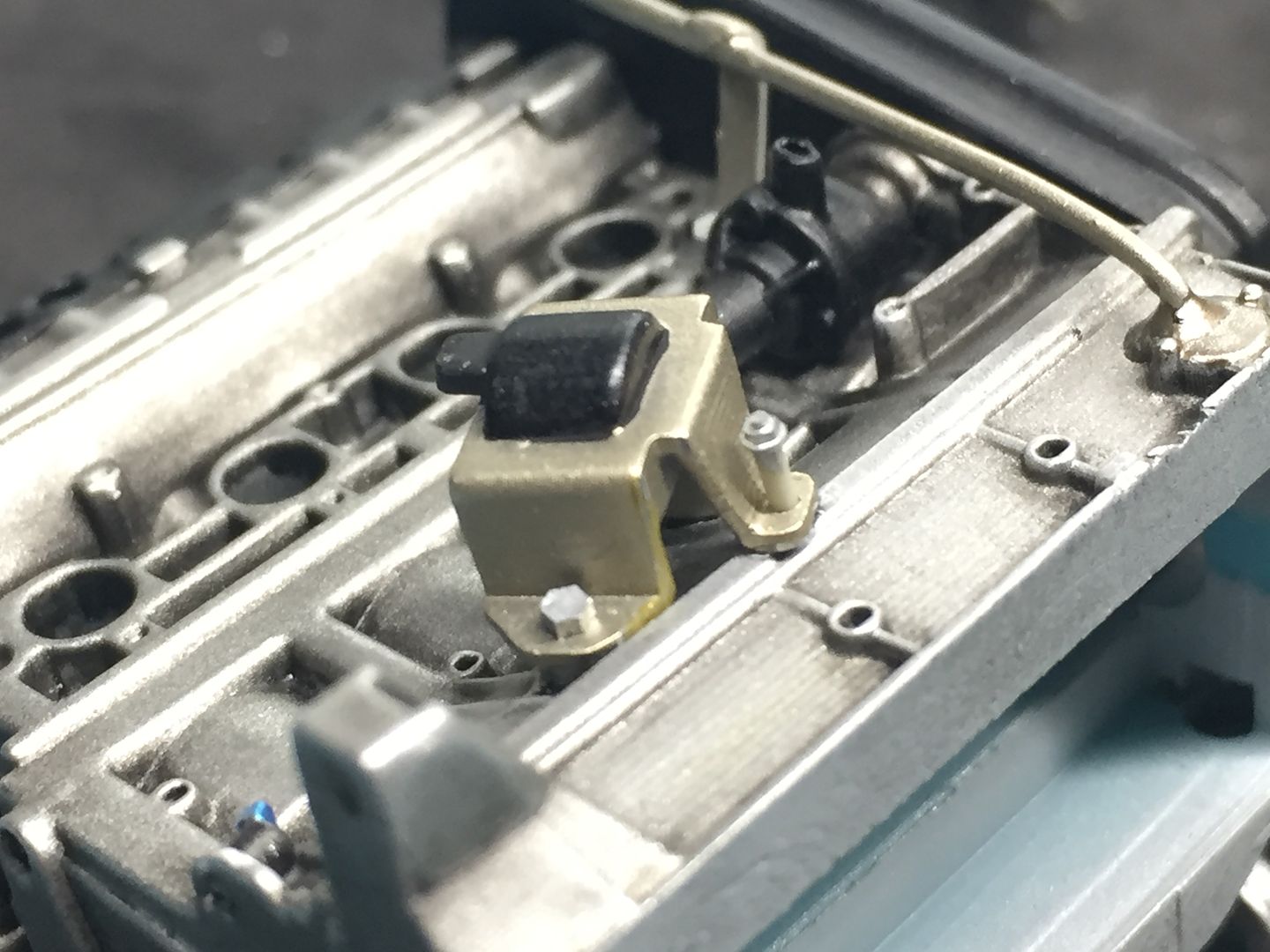
Having tried the 1/8th scale, I thought I'd try a 1/43rd one-piece engine, just to see!
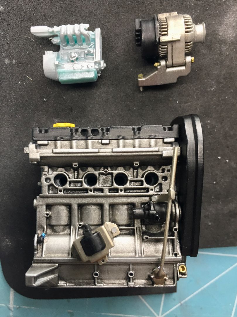
Tip time!
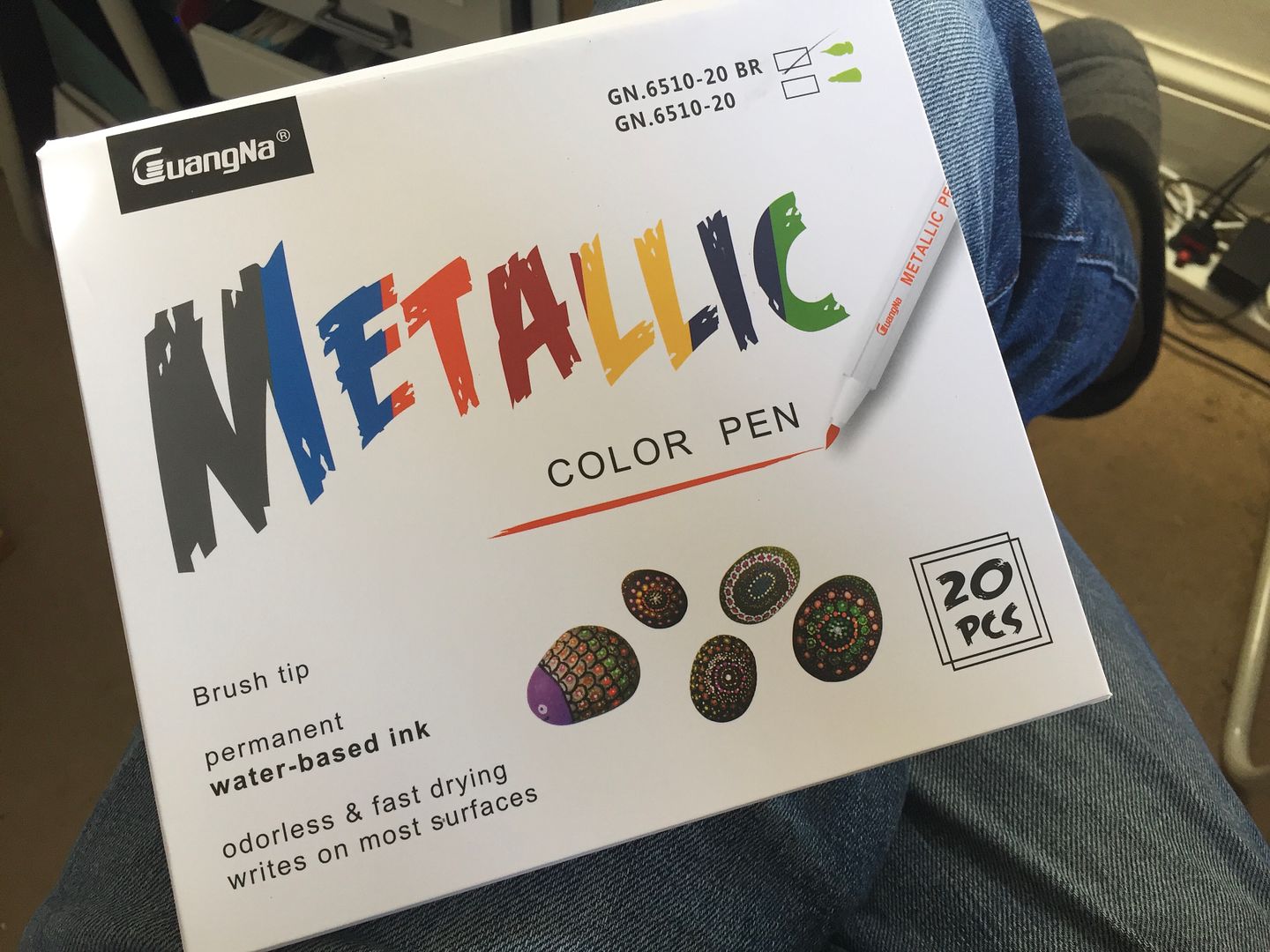
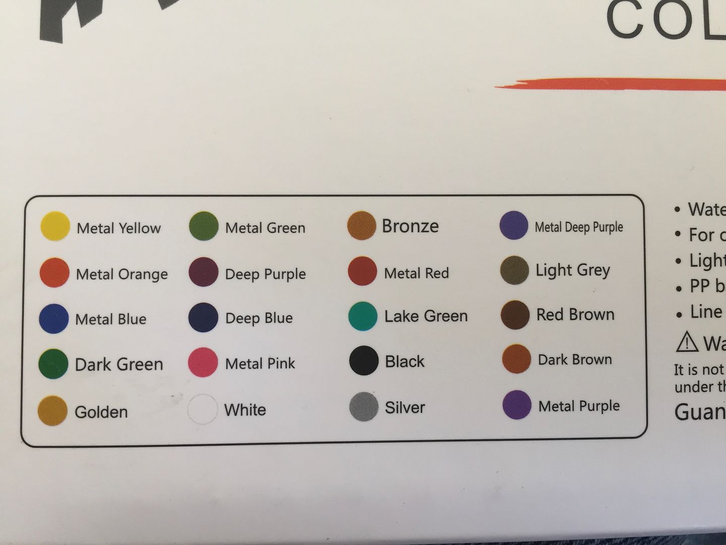
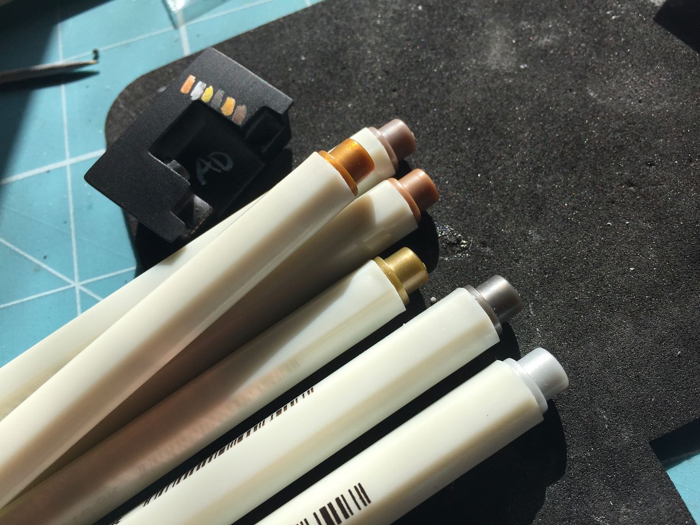
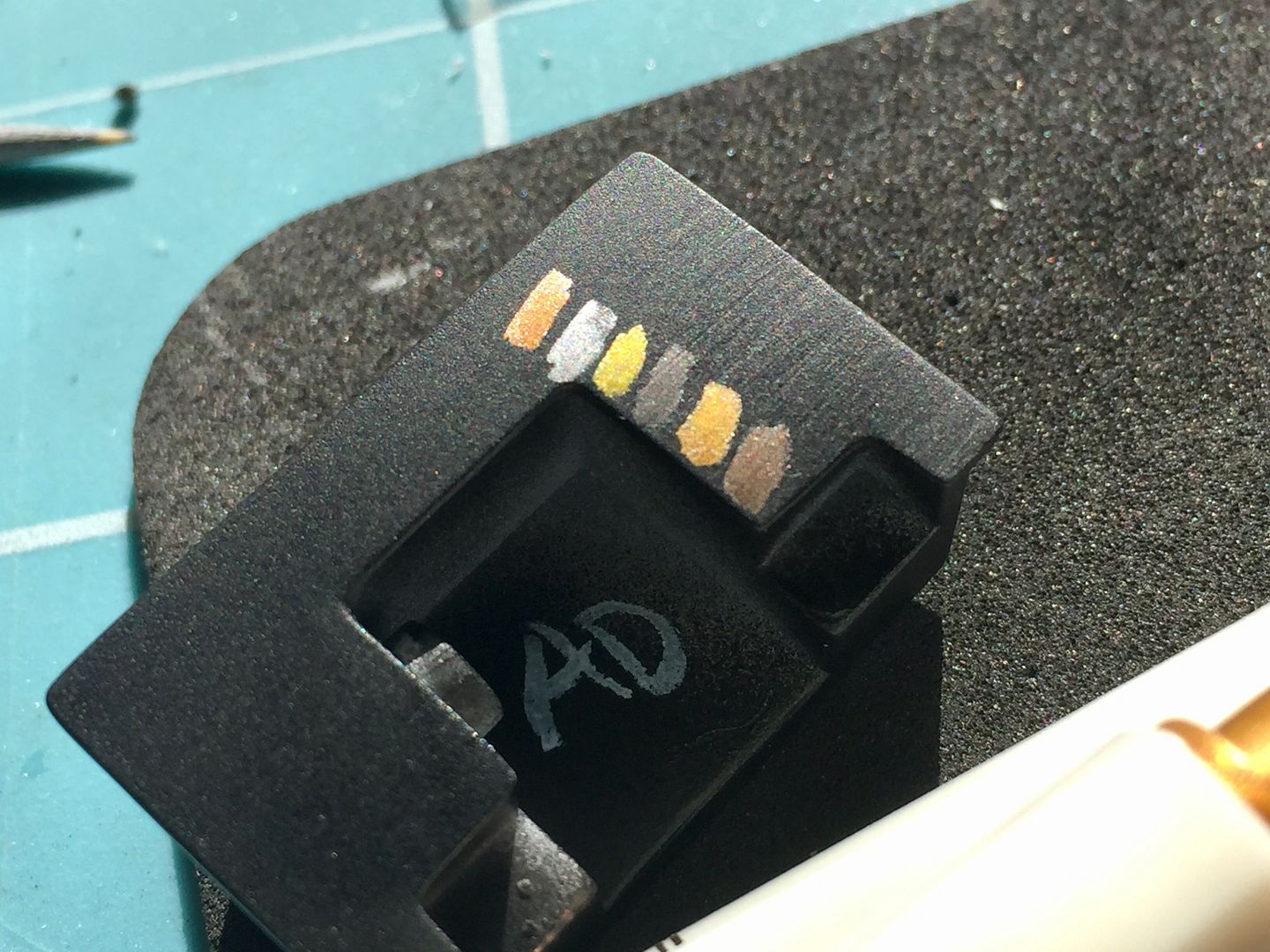
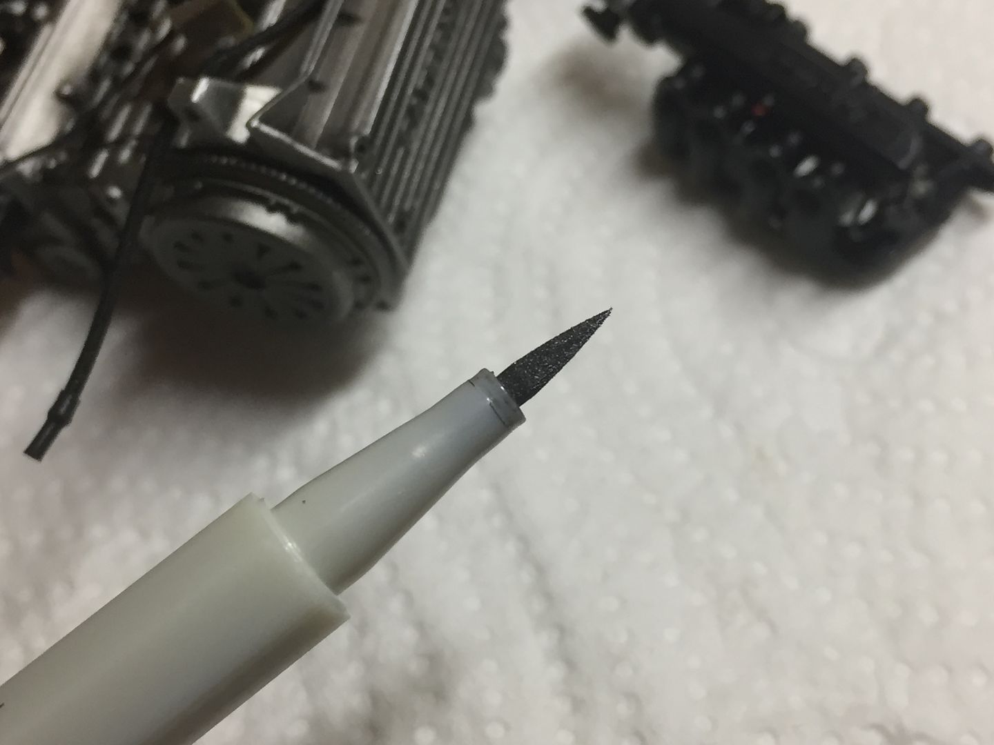
Metallic paint pens (crafts etc - Amazon) - brilliant for different metallic finishes and easier to apply to details! About £10 for loads...
Dip stick next....
Having scratch built the 2 engines on the R500's out of wood, plastic etc, machined slots in the cam cover etc etc, I wanted to 3D print these. But that meant drawing a k-series up in CAD. I'm self-teaching, so it was a bit daunting - but once you know where the buttons are, an engien block is not actually so complicated...
I took measurements from many photos I have of our engine over the years, and measured the engine outside in the car - which due to access is actually pretty difficult - I could measure the cam cover easily, but that was about it - but long story short, I was able to scale the photos once I had a base measurement. Once I had pretty much finished with the CAD and engine build, I had access to a real engine that was not in the car, and measuring this I found I had been pretty damn close.
I drew the engine 1:1 (I can scale when I print) and I have split it into the actual parts - so the block consists of 5-6 'layers' (although I printed the middle bits in one lump) I found out that the easiest way to model and build the engine is to do it exactly the same as the real one - so the alternator is attached with a bracket in the same way as 1:1, coil is bolted on the same way, throttle uses 4 bolts etc etc.
I had a few parts lying around - like the sump - which I was able to measure properly and then scale others from that.

Richards car has the plastic Rover air intake, which was going to be a challenge to draw for me in CAD.


I started roughing out the overall shape - main measurements were the height of each layer in the block. Once I got those correct, I added most of the detail in by eye.
I printed a VERY rough block to see if the size/scale was going to work, then a slightly more refined version at different stages. I'm learning about the 3D printing as well, and you learn to design the parts to make the printing process - particularly the orientation on the build plate - easier. The large holes are for the resin to drain - I hollowed out the 'real' one later.


example of the 3d printer plate layout/slicing - where you add supports etc - I'm learning!

Some examples of parts being printed - there were lots of versions, so these photos cover about a months work from now on!


I'd do the occasional print with everything 'turned on' in the assembly, just to see the size etc - in the end, every component, like coil, sump, bellhousing etc was made separately.


But it was getting there...

Here are some screenshots of the complete engine in CAD...


I printed a 1/8th scale block - 'just to see' - ummm - 1/8th scale model....


Eventually I got to the point where I was happy with the block - you can see the progression here:

Next I made the ancillaries that bolt to the block - alternator, coil, air intake, throttle, cam belt cover, pulley, starter motor etc etc etc

I drew up the alternator in three parts - the casting, the black plastic cap at the end and the center coil. This would make the painting easier, and allow open vents etc. I could have made the pulley separate I guess...


I added the new parts to a test block to test the fit...


Drilling the alternator bracket...

There comes a point where you think 'what am I doing modelling this...?!' - in this case, it was when i was drawing up the crank sensor...

By far the smallest part I have printed..

(get used to that pen)

Adding paint really transforms everything!


That crank sensor needed a flywheel - which needed a clutch (which would be hidden by the bellhousing, visible in only a few gaps - but what the hell - in for a penny, in for a pound!!


Forgot the gloves...


Testing silvers for the block...


I used an oil wash to make it look grubby with.....oil!


..and started to paint and add the other parts - here is the coil being bolted in place...

Having tried the 1/8th scale, I thought I'd try a 1/43rd one-piece engine, just to see!


Tip time!
Metallic paint pens (crafts etc - Amazon) - brilliant for different metallic finishes and easier to apply to details! About £10 for loads...


Dip stick next....
dr_gn said:
Awesome as usual!
My only comment (not that you’ve asked), would be that to my eyes the metallic paint is too coarse - 1:1 metallic flakes on a 1:12 car.
cheers Doc - welcome any comments from you!My only comment (not that you’ve asked), would be that to my eyes the metallic paint is too coarse - 1:1 metallic flakes on a 1:12 car.
I know what you mean, and it is something you often notice with metallic cars - that is why I like the Alclad paints!
But this is using the actual paint from a specific car to perfectly match - do you know any tips for reducing the effect? This is a Ferrari colour.
Actually, when viewed by eye it is far less obvious - of course taking the pictures the strong lights I had exaggerate the effect a little....
caterhamnut said:
dr_gn said:
Awesome as usual!
My only comment (not that you’ve asked), would be that to my eyes the metallic paint is too coarse - 1:1 metallic flakes on a 1:12 car.
cheers Doc - welcome any comments from you!My only comment (not that you’ve asked), would be that to my eyes the metallic paint is too coarse - 1:1 metallic flakes on a 1:12 car.
I know what you mean, and it is something you often notice with metallic cars - that is why I like the Alclad paints!
But this is using the actual paint from a specific car to perfectly match - do you know any tips for reducing the effect? This is a Ferrari colour.
Actually, when viewed by eye it is far less obvious - of course taking the pictures the strong lights I had exaggerate the effect a little....
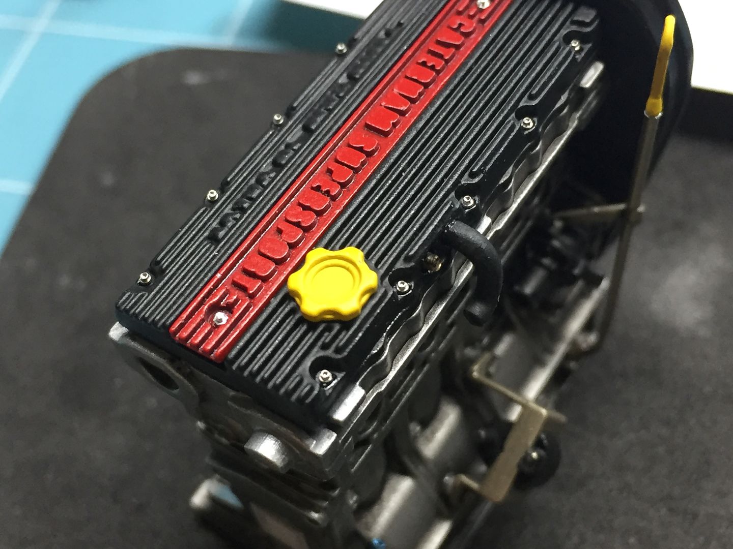
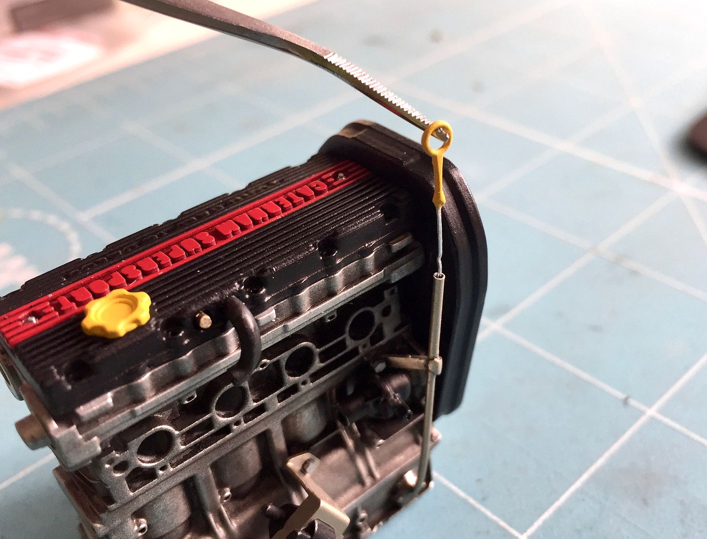
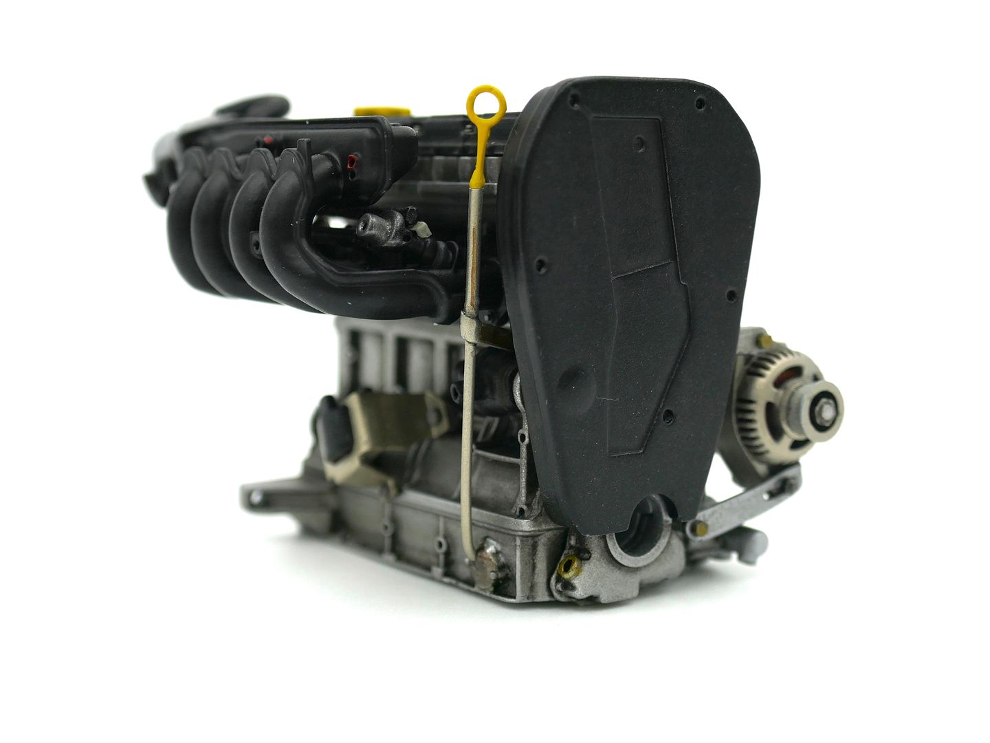
Dipstick!
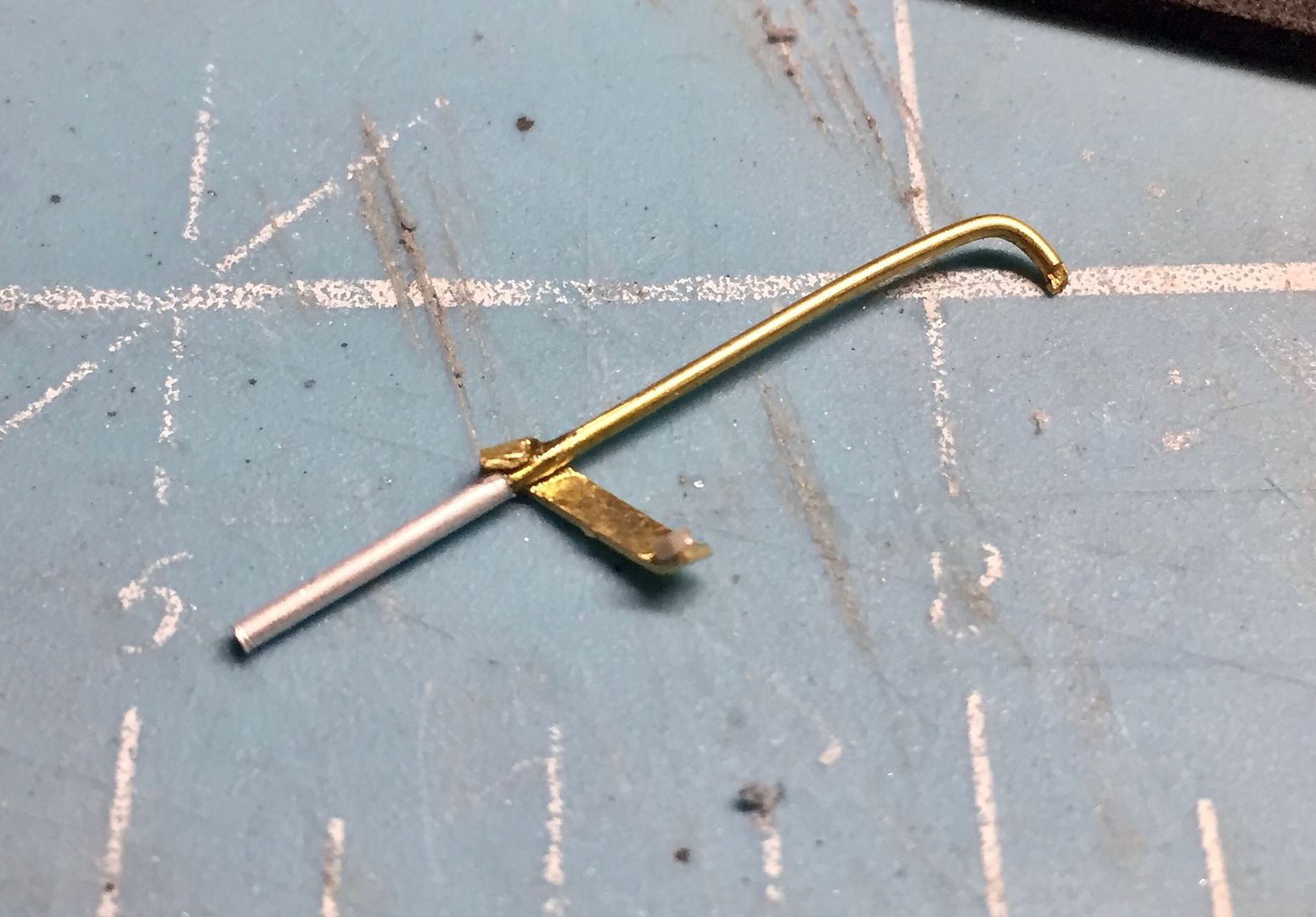
Brass and ali tubing for the dipstick tube, and I printed the 'handle' - another tiny part!
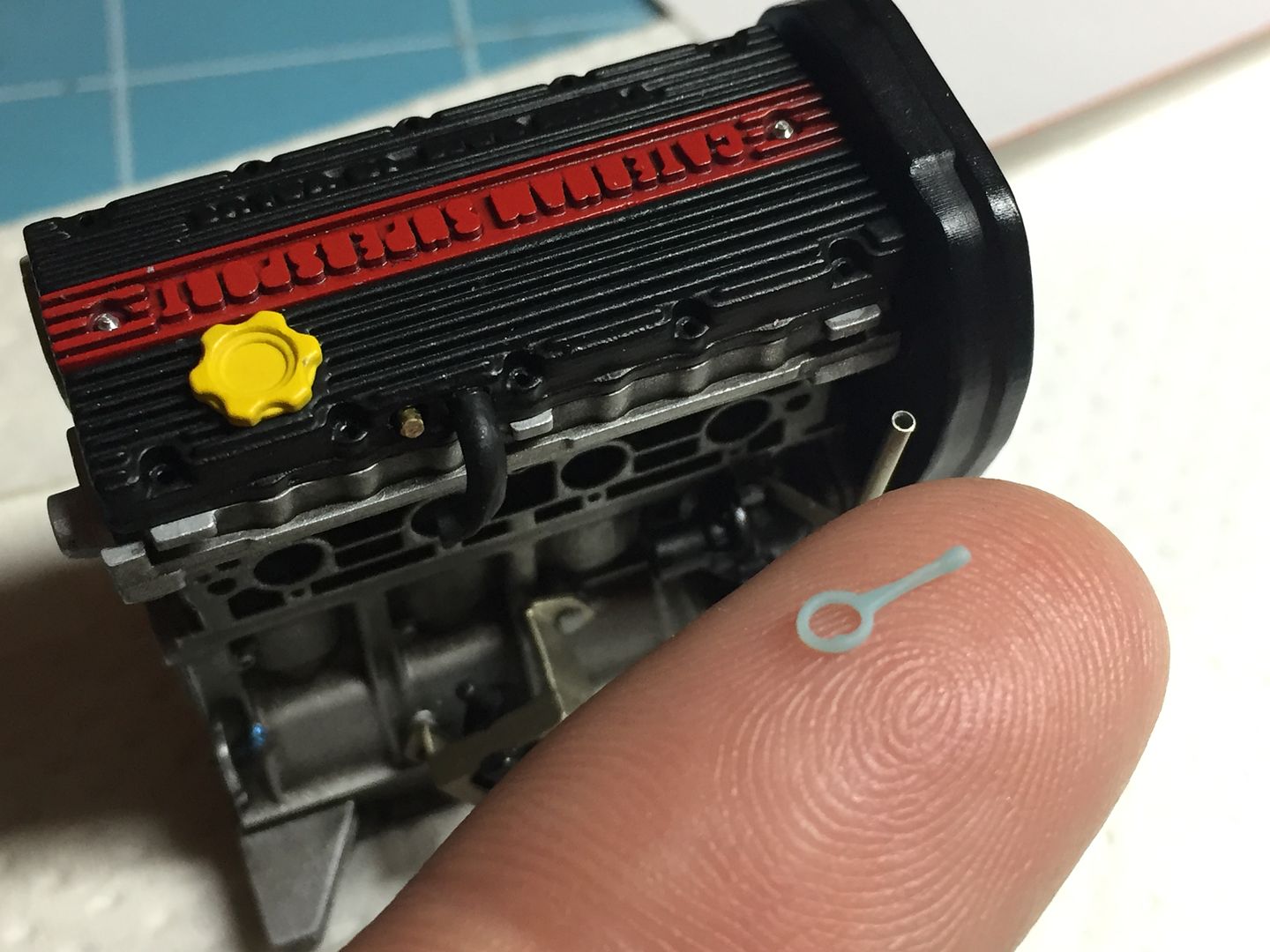
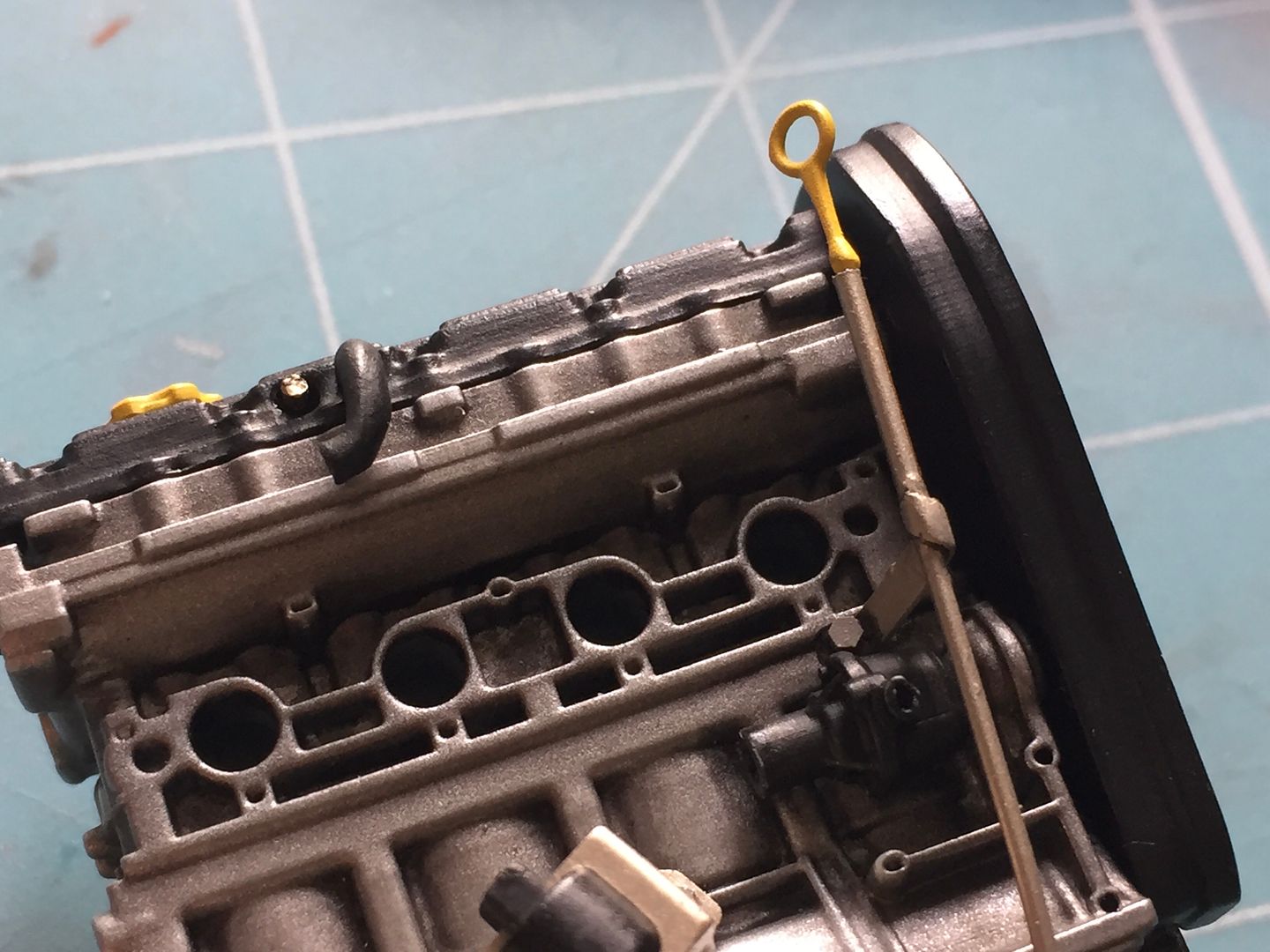
of course it 'works'....
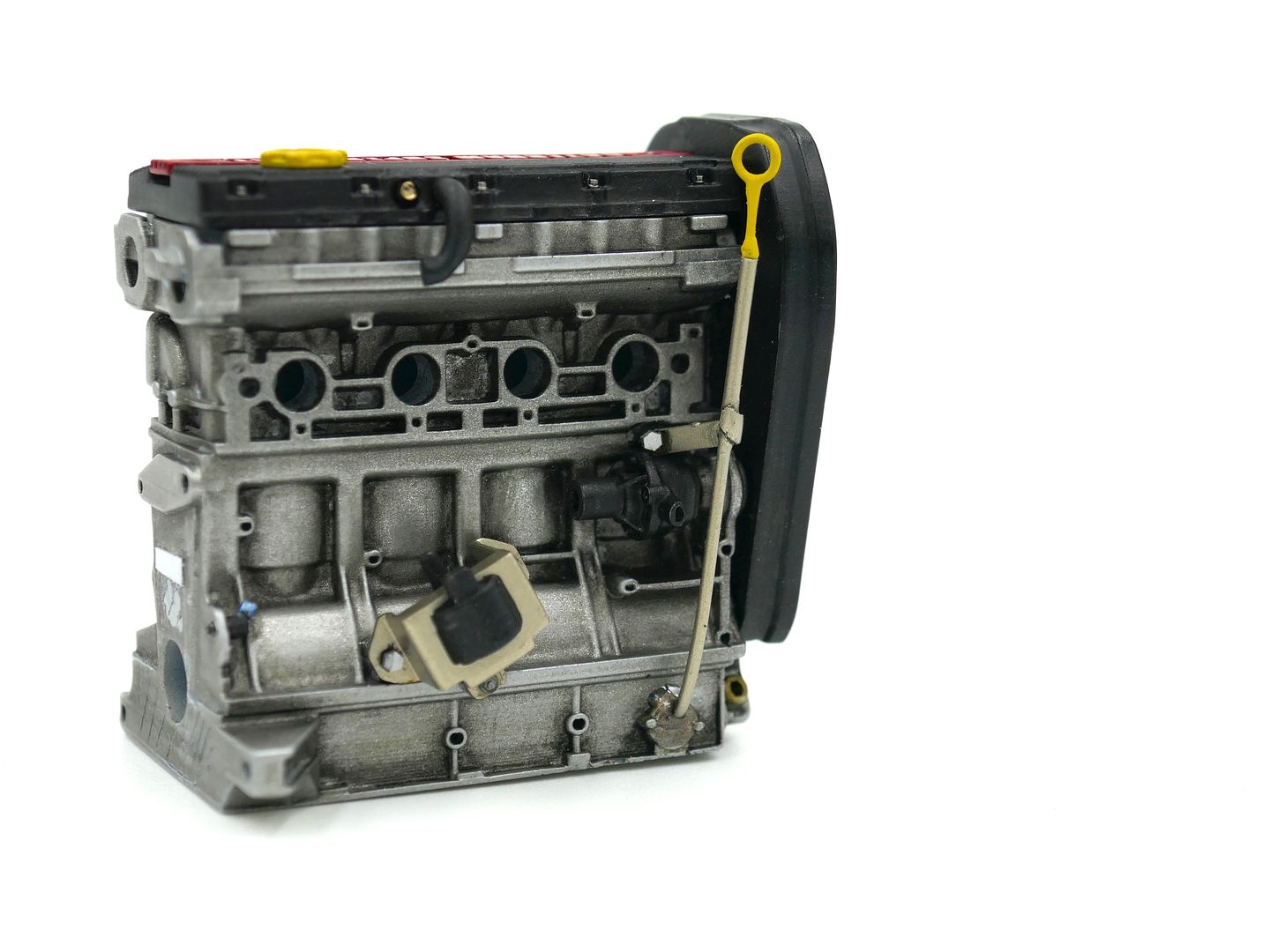
So that was the main block sorted - the starter motor goes on after the bell housing...
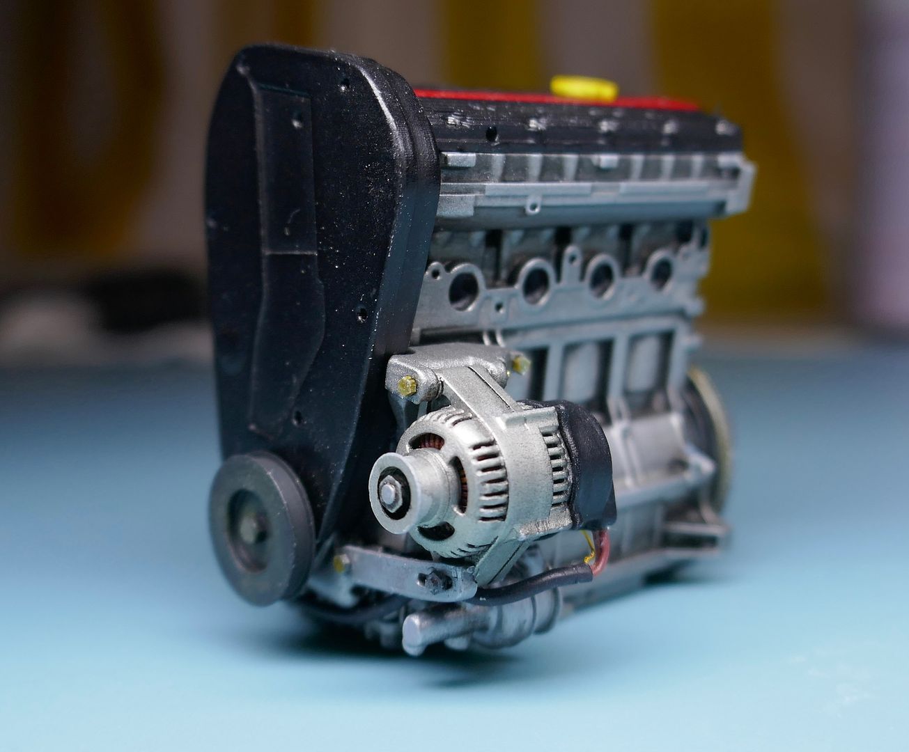
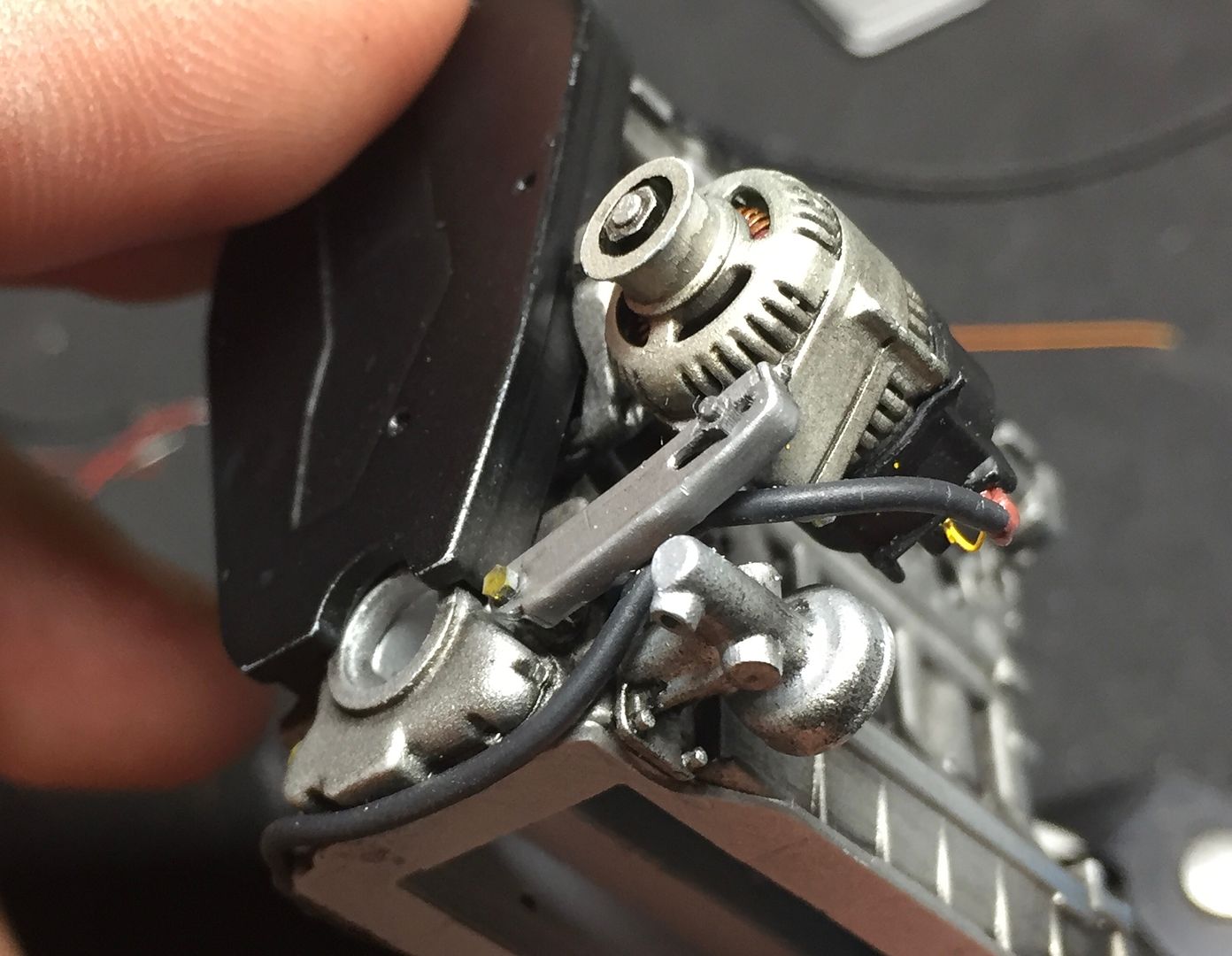
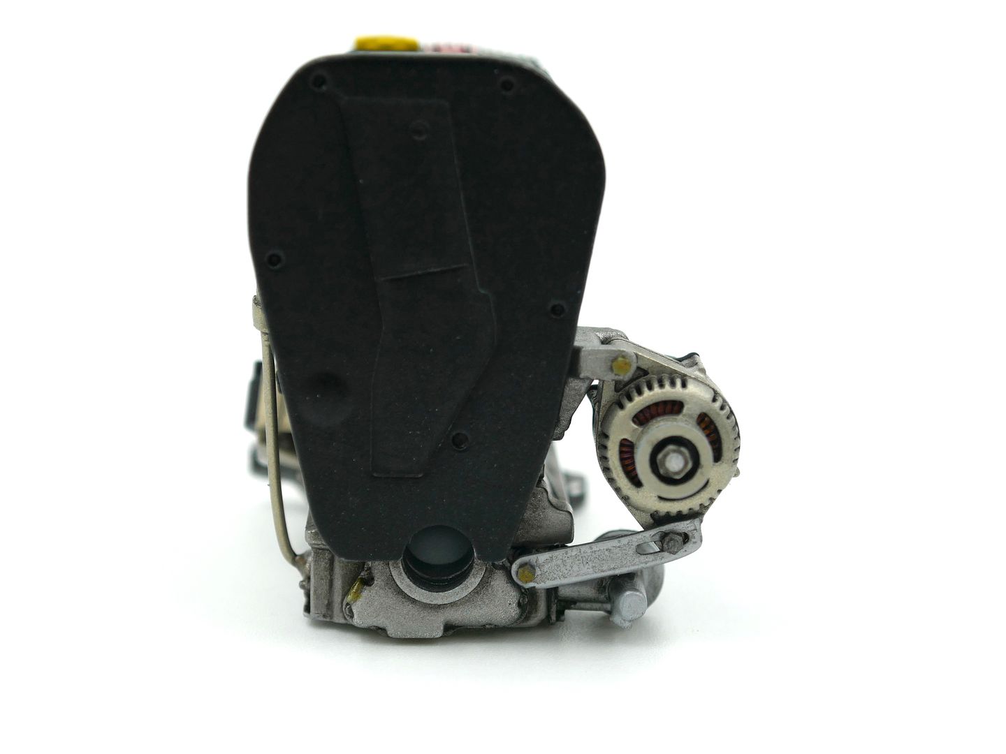
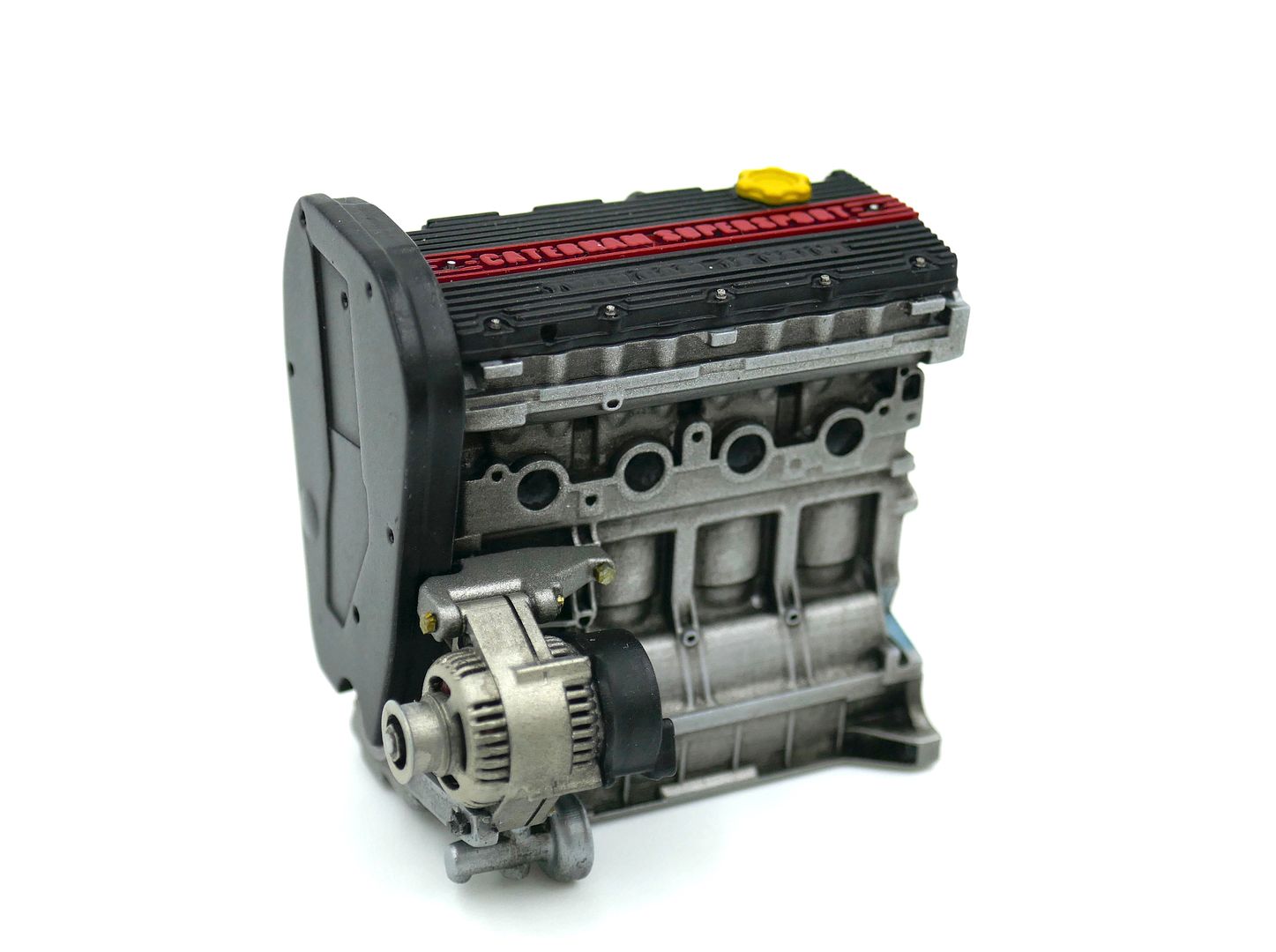
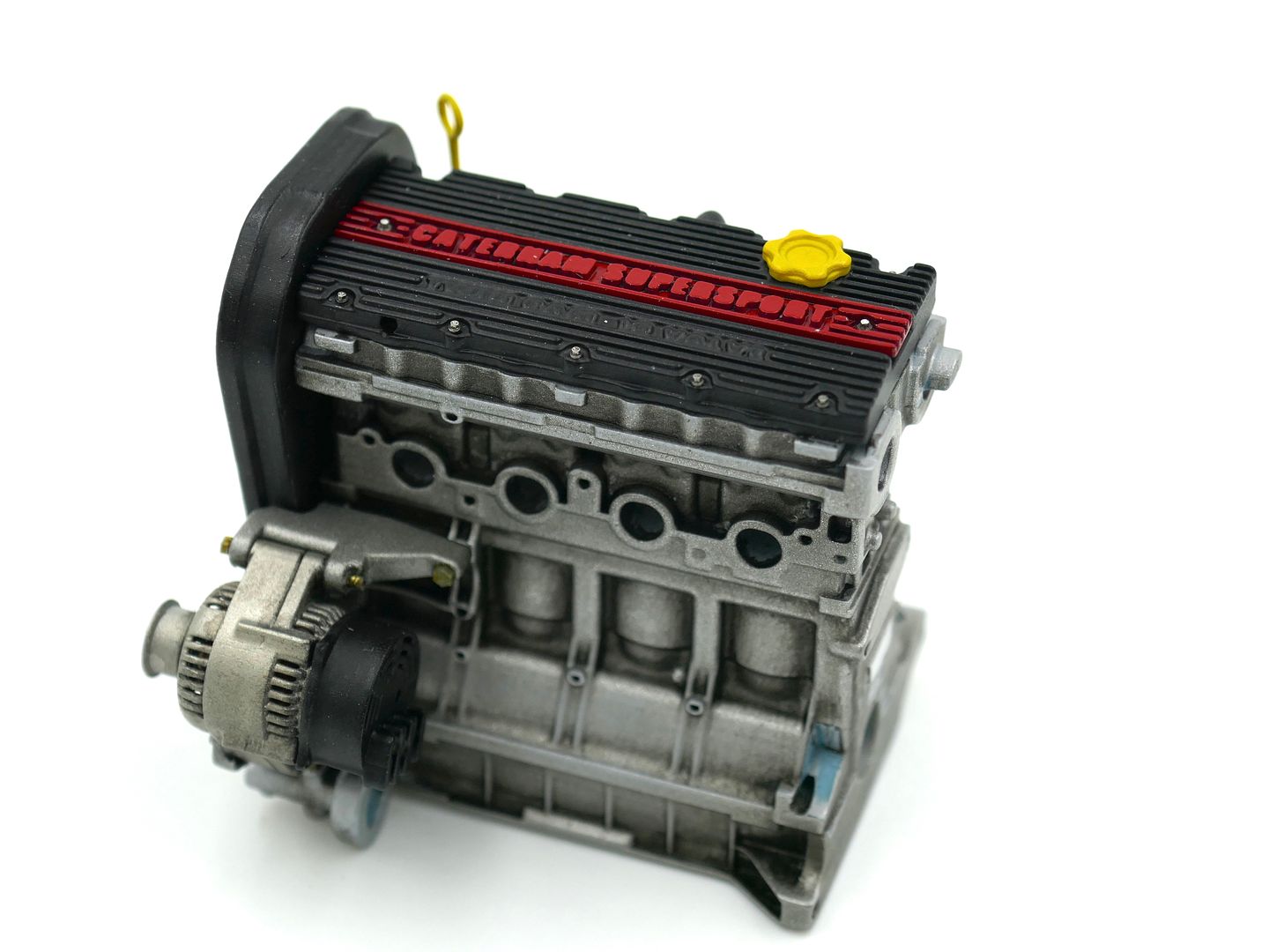
You can see I have also started to add some wiring to the block.
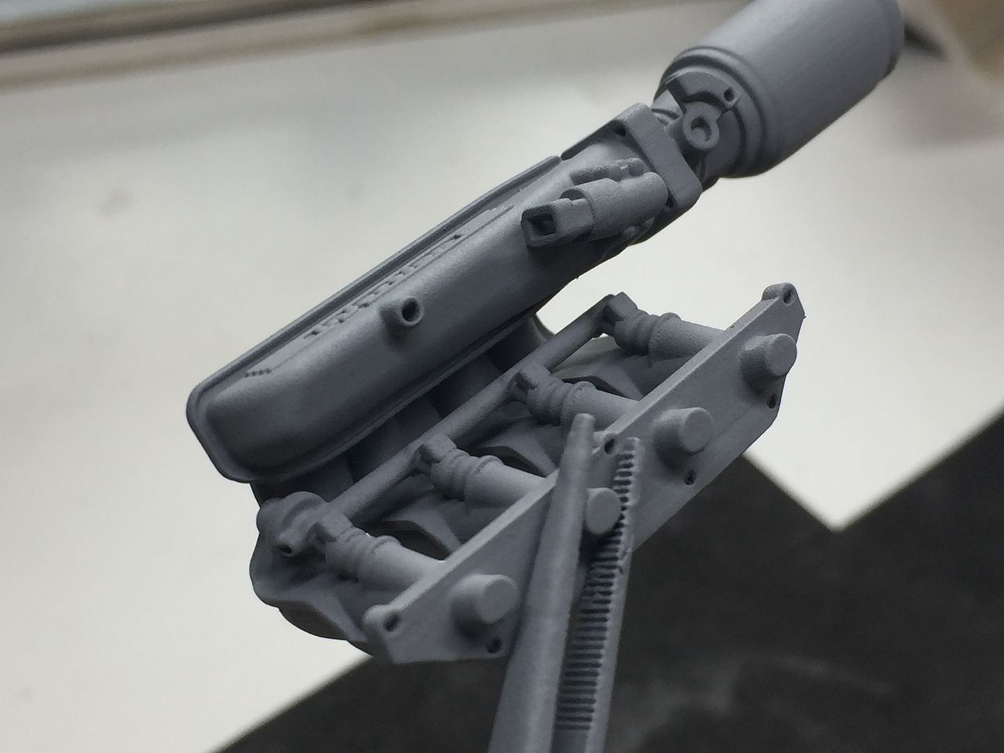
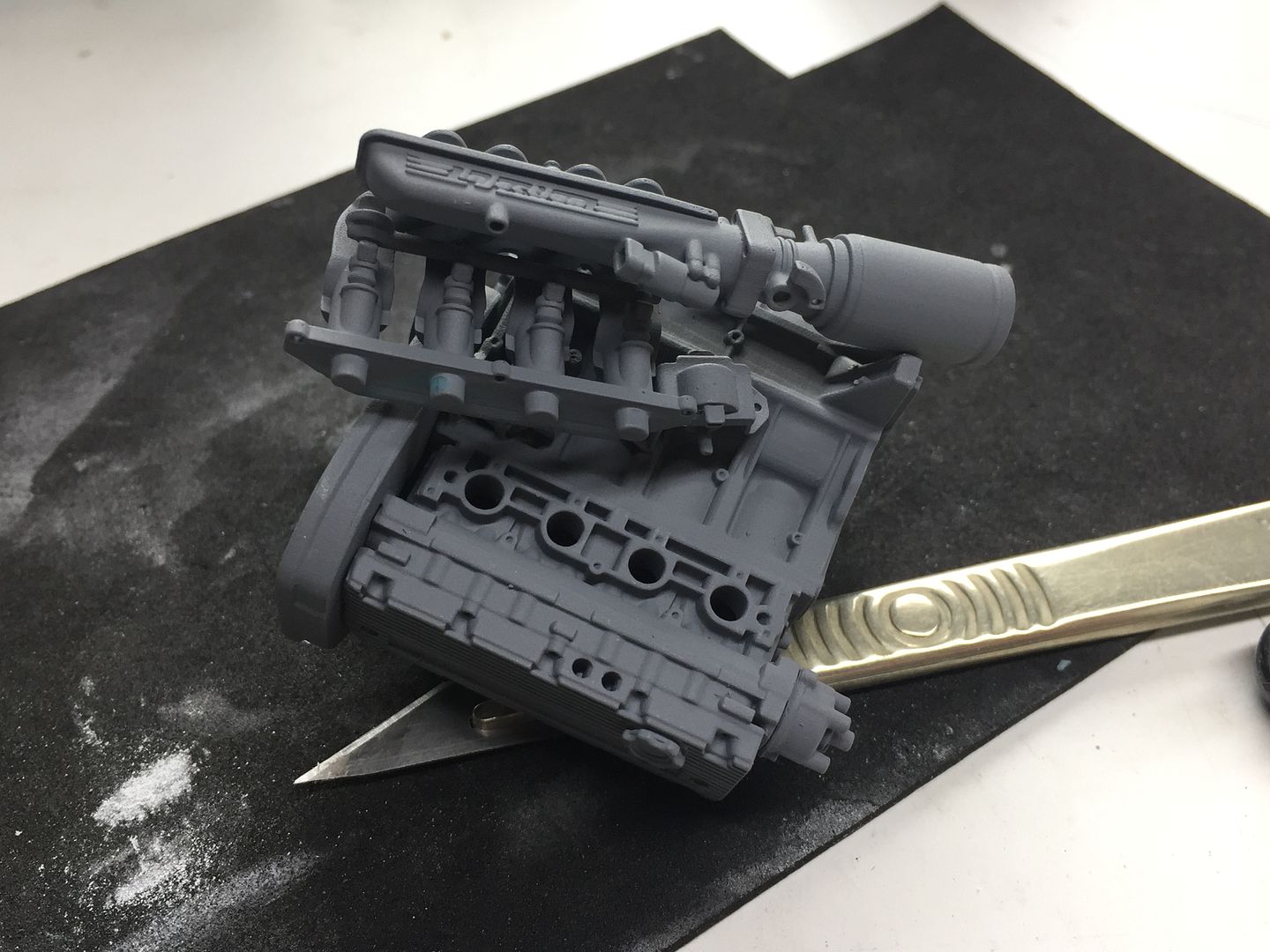
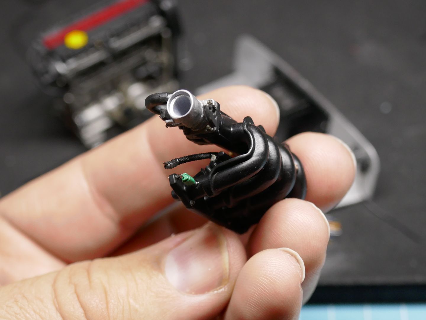
But the next big bit to model was the air intake manifold. This was going to be a challenge in CAD for me, but managed it - best way to learn a program is a 'real' project! So the end result works, but it is by no means a 'good' CAD model! The splits involved made drawing and printing it more easily. The throttle is made separately and bolted together after painting, as will be the foam air filter.
I don't have this part on my car anymore, so had to rely on photos - although I was able to go and measure some bits halfway through the process - ebay and autofactors are good resources for parts pictures by the way...
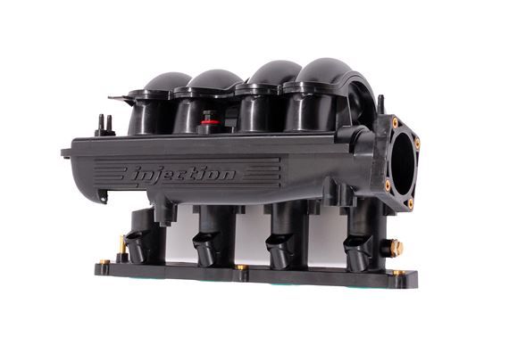
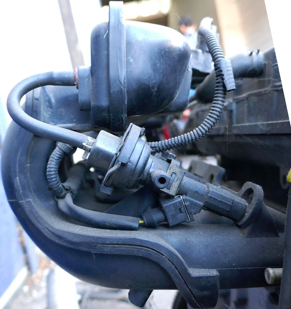
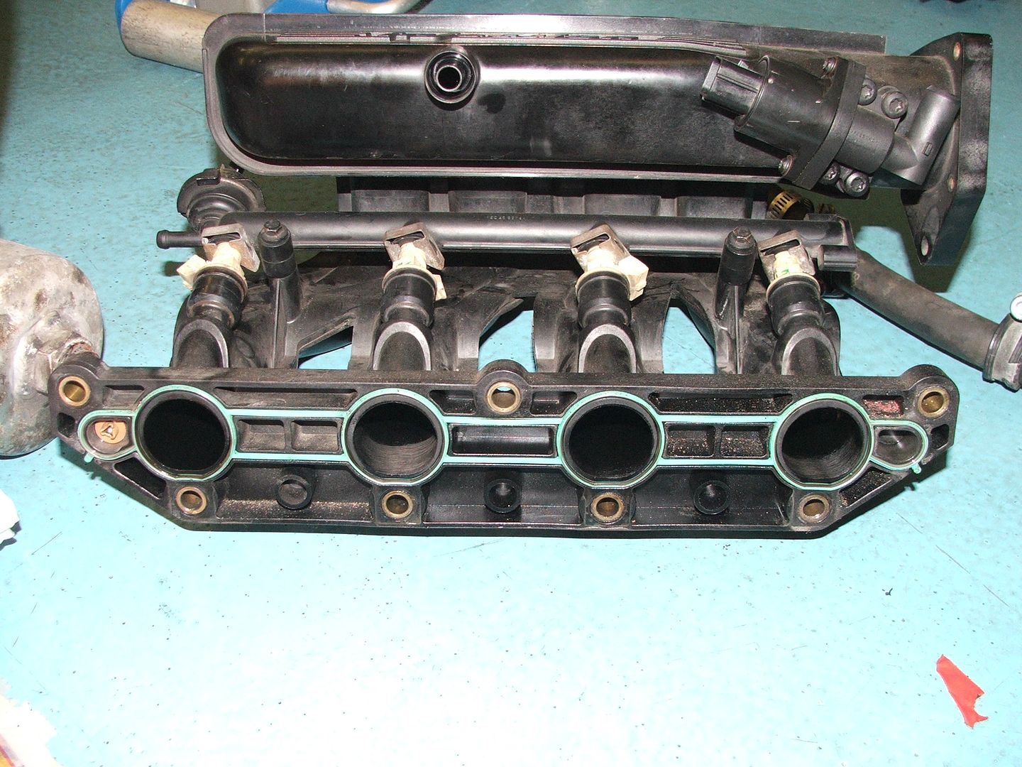
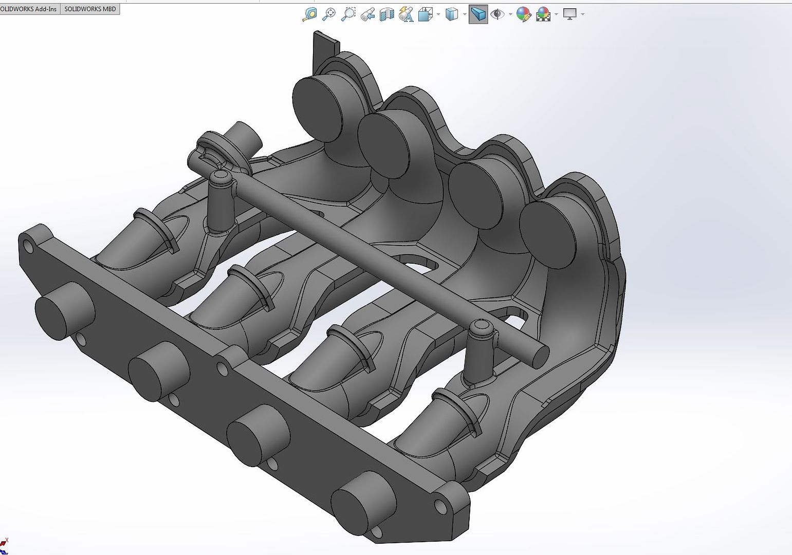
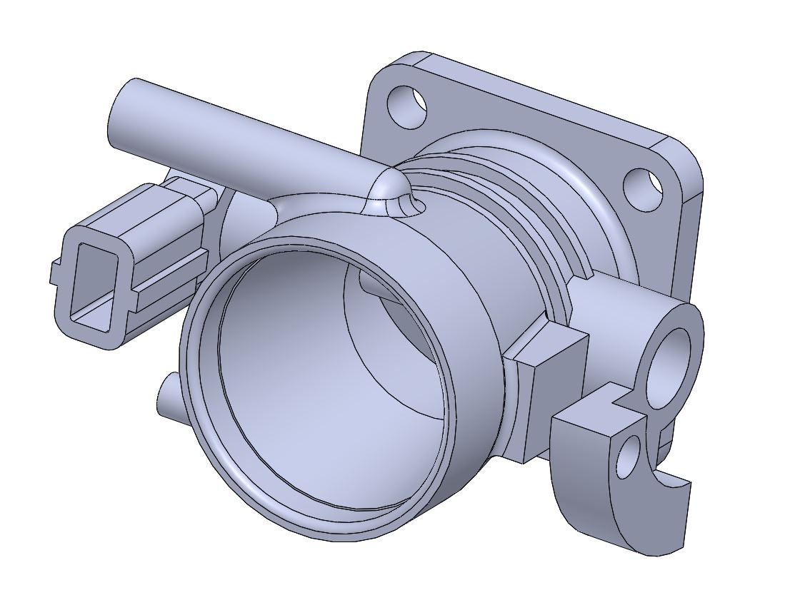
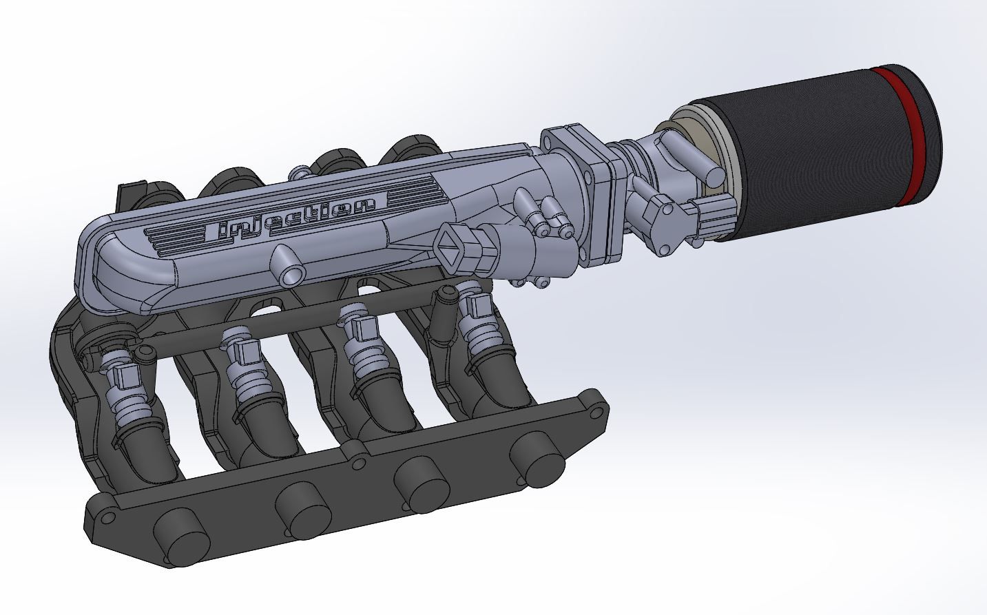
Test print of the whole air intake assembly, to check fit and scale etc
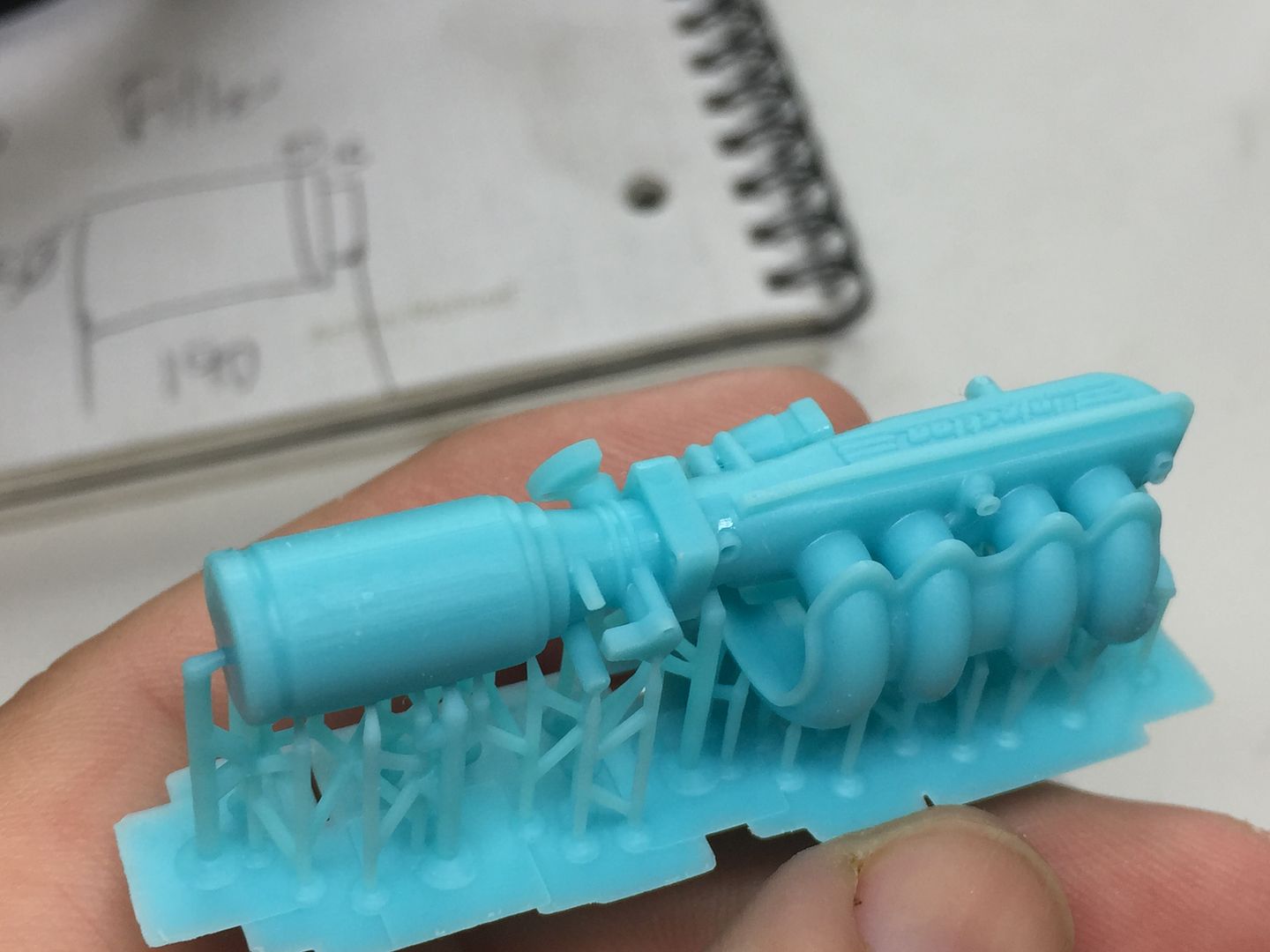
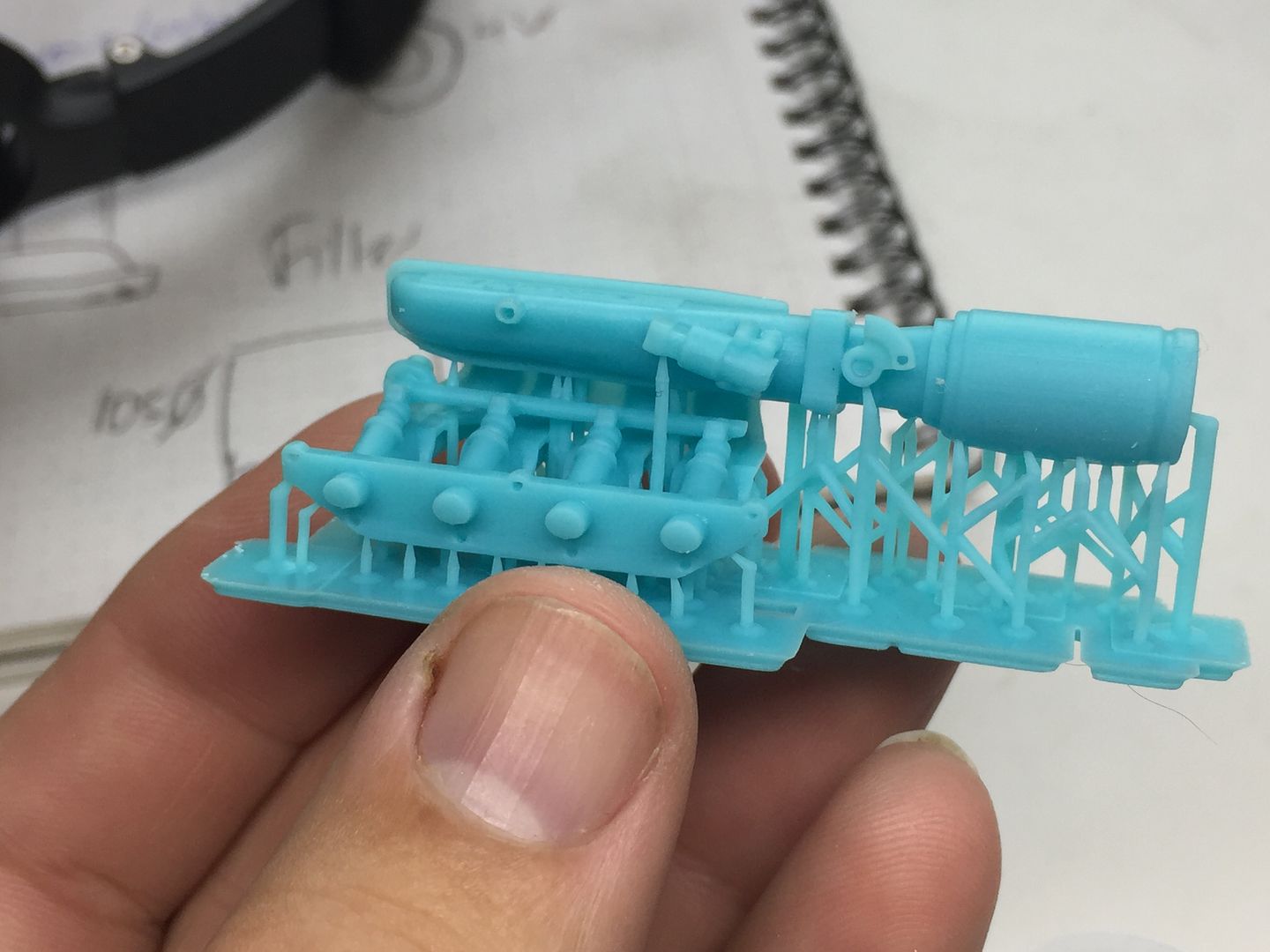
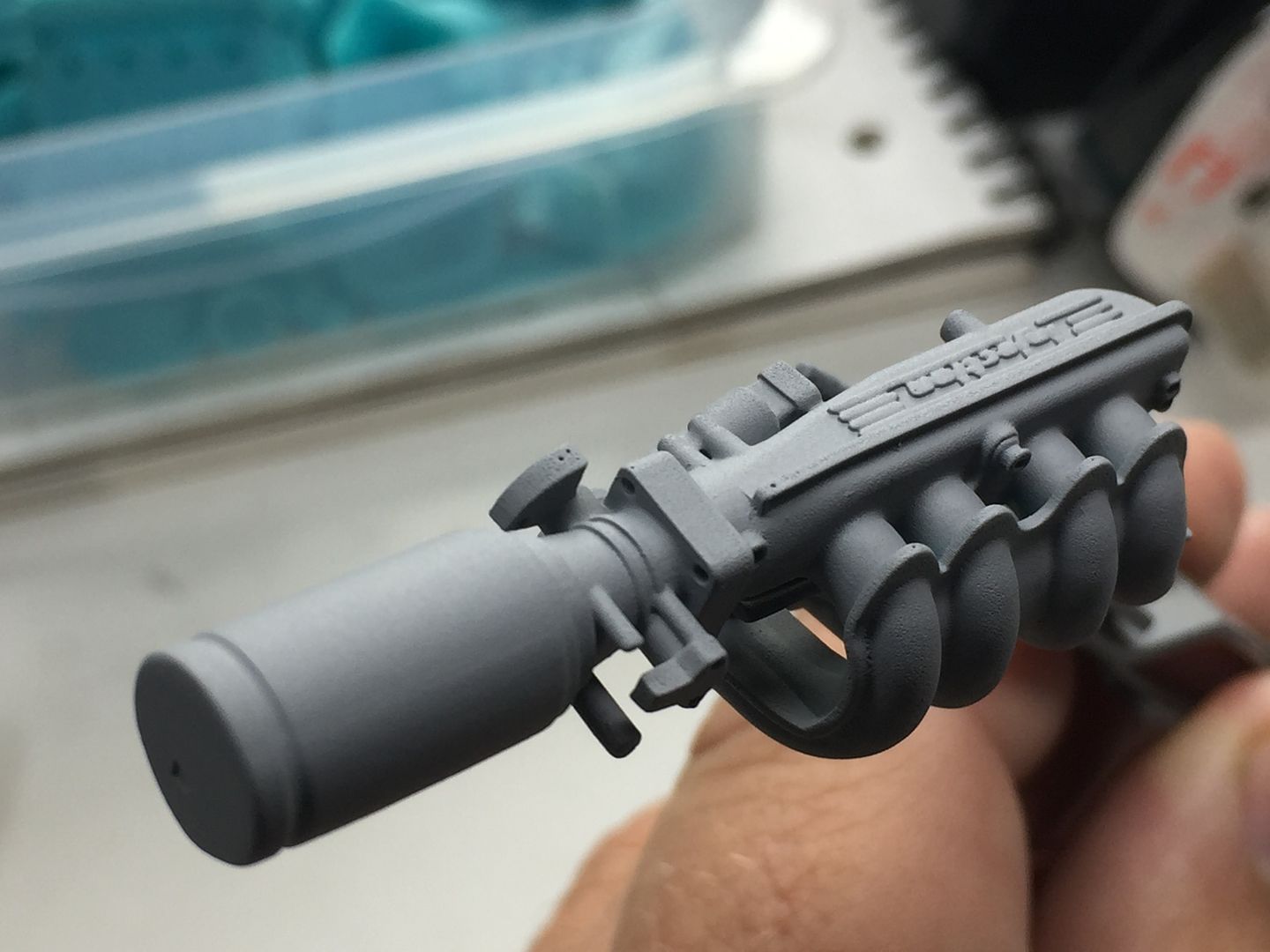
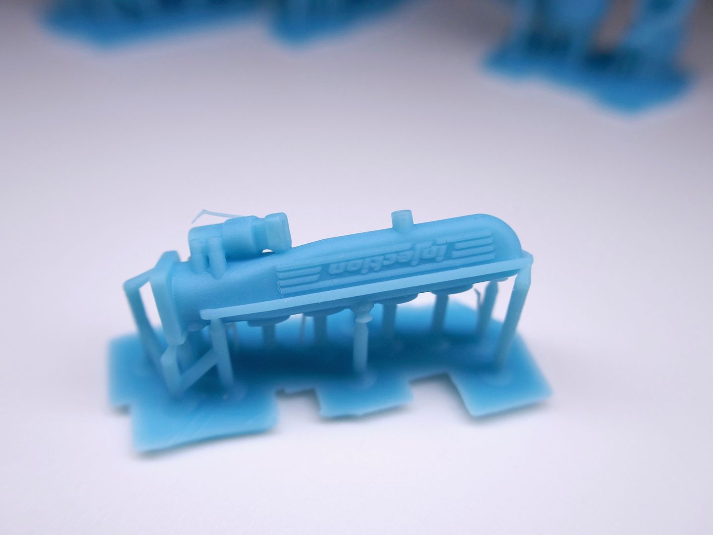
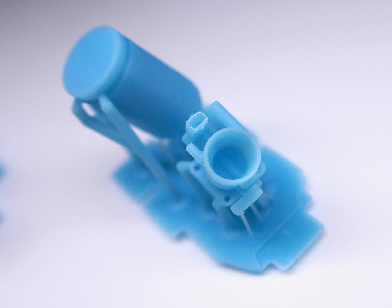
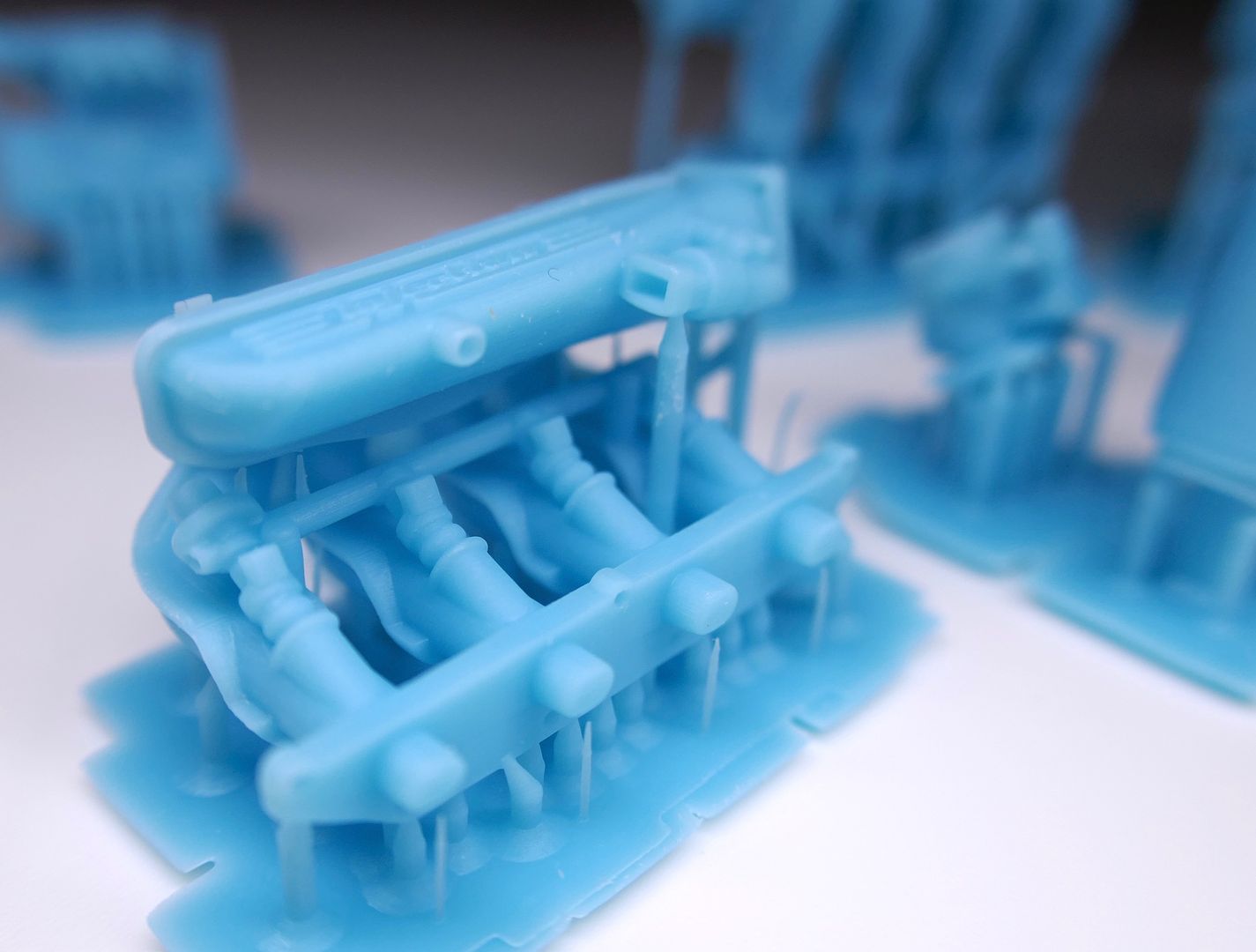
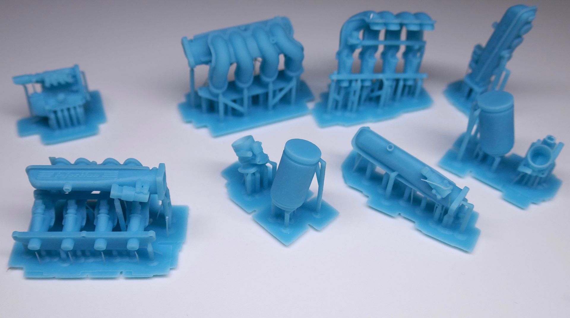
Lots of test prints to find the best orientation etc
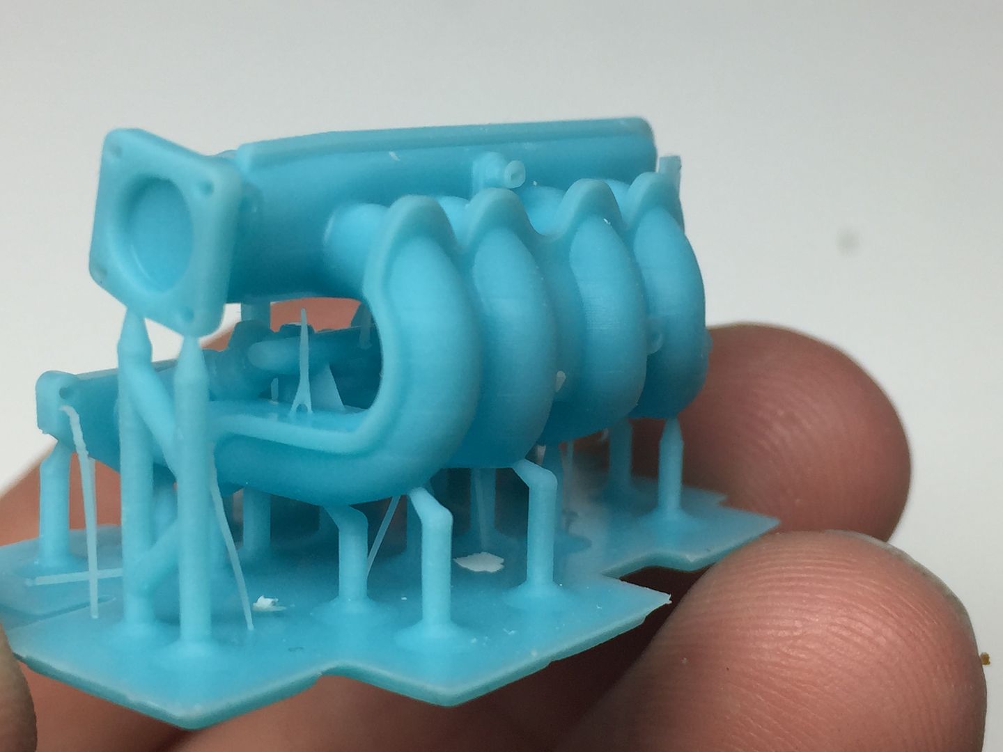
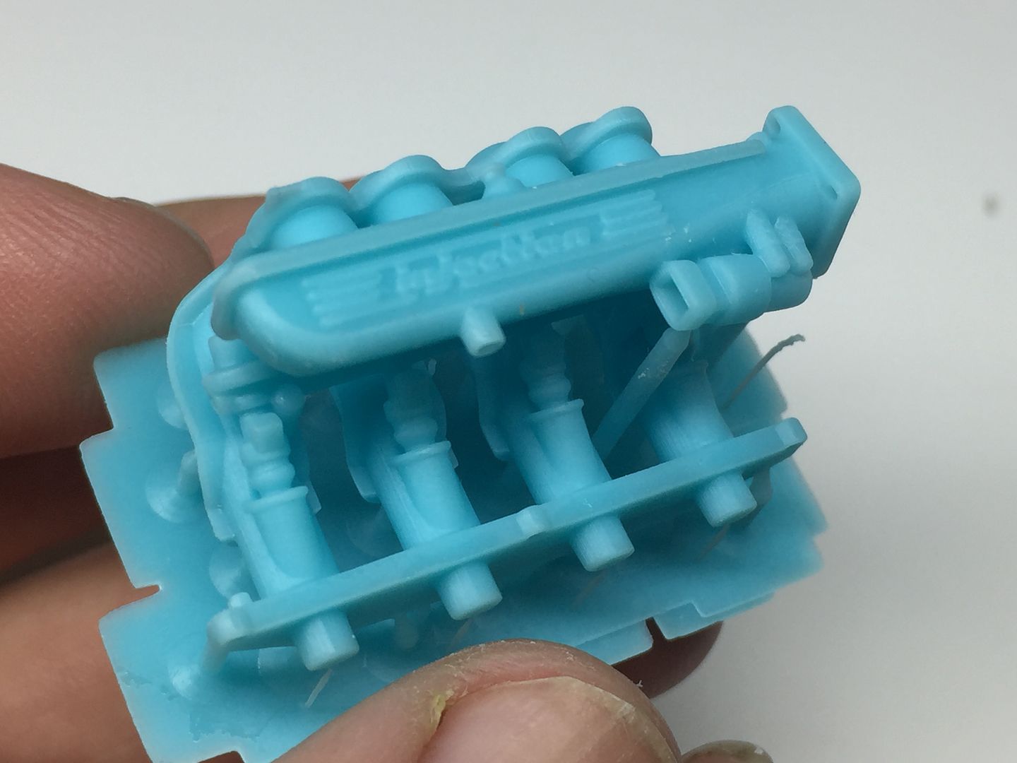
At this point I glued all the bits together and primed one version, just to get a clear overall view, and again, to test fit!
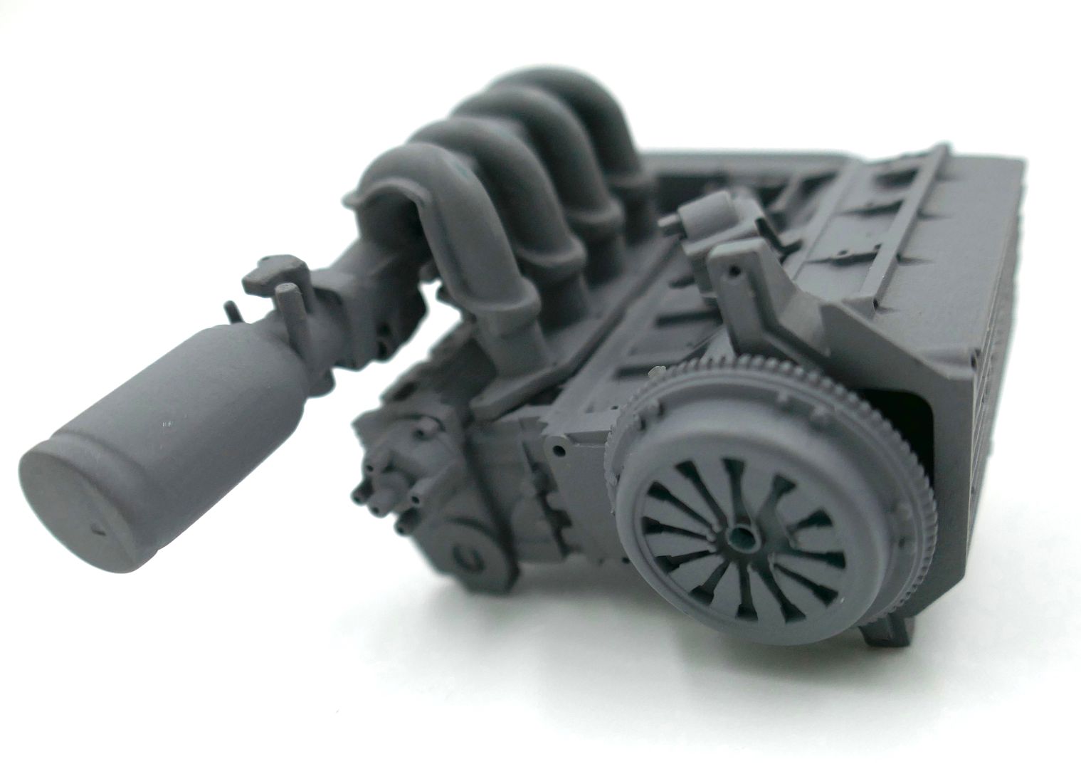
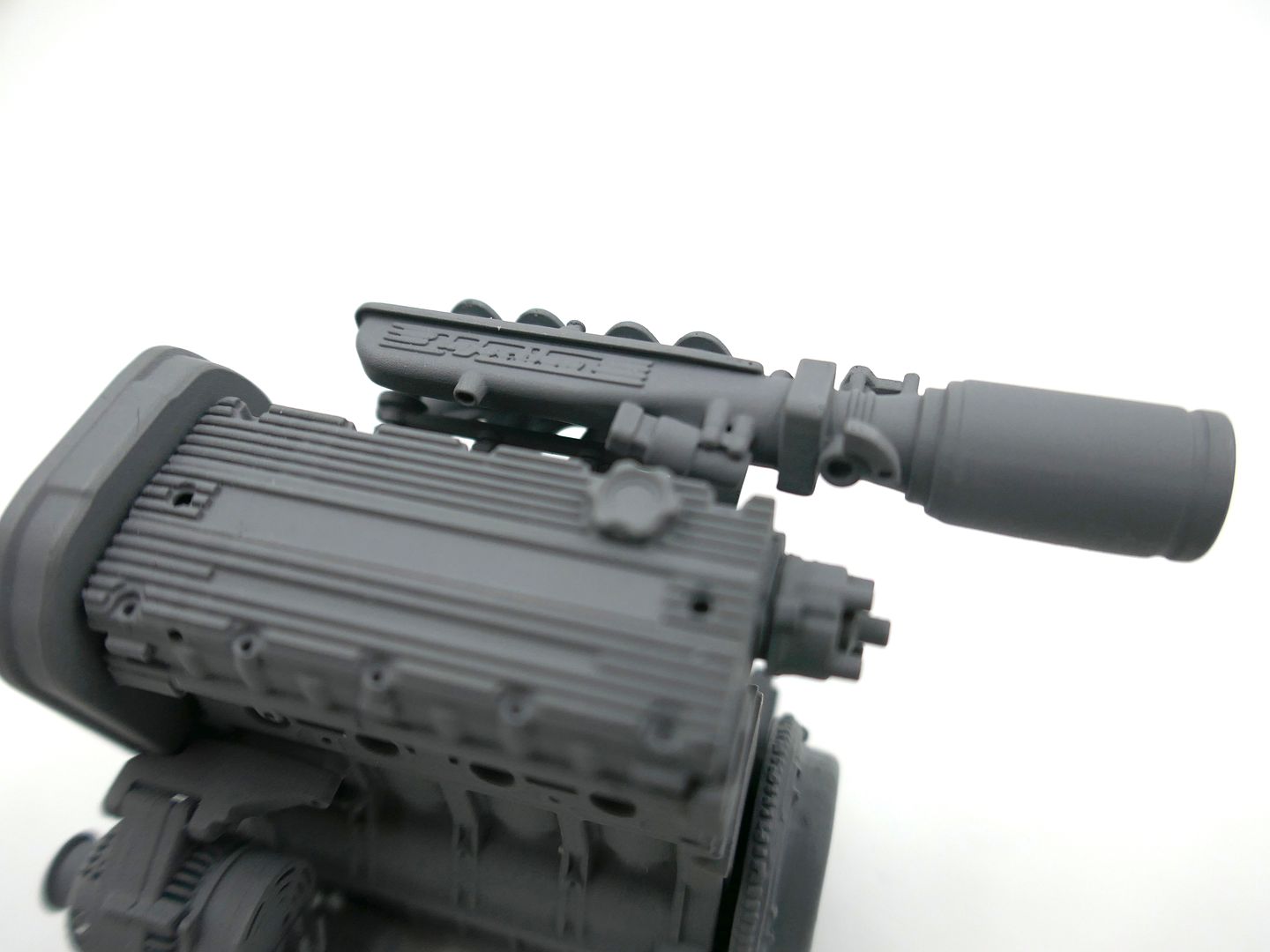
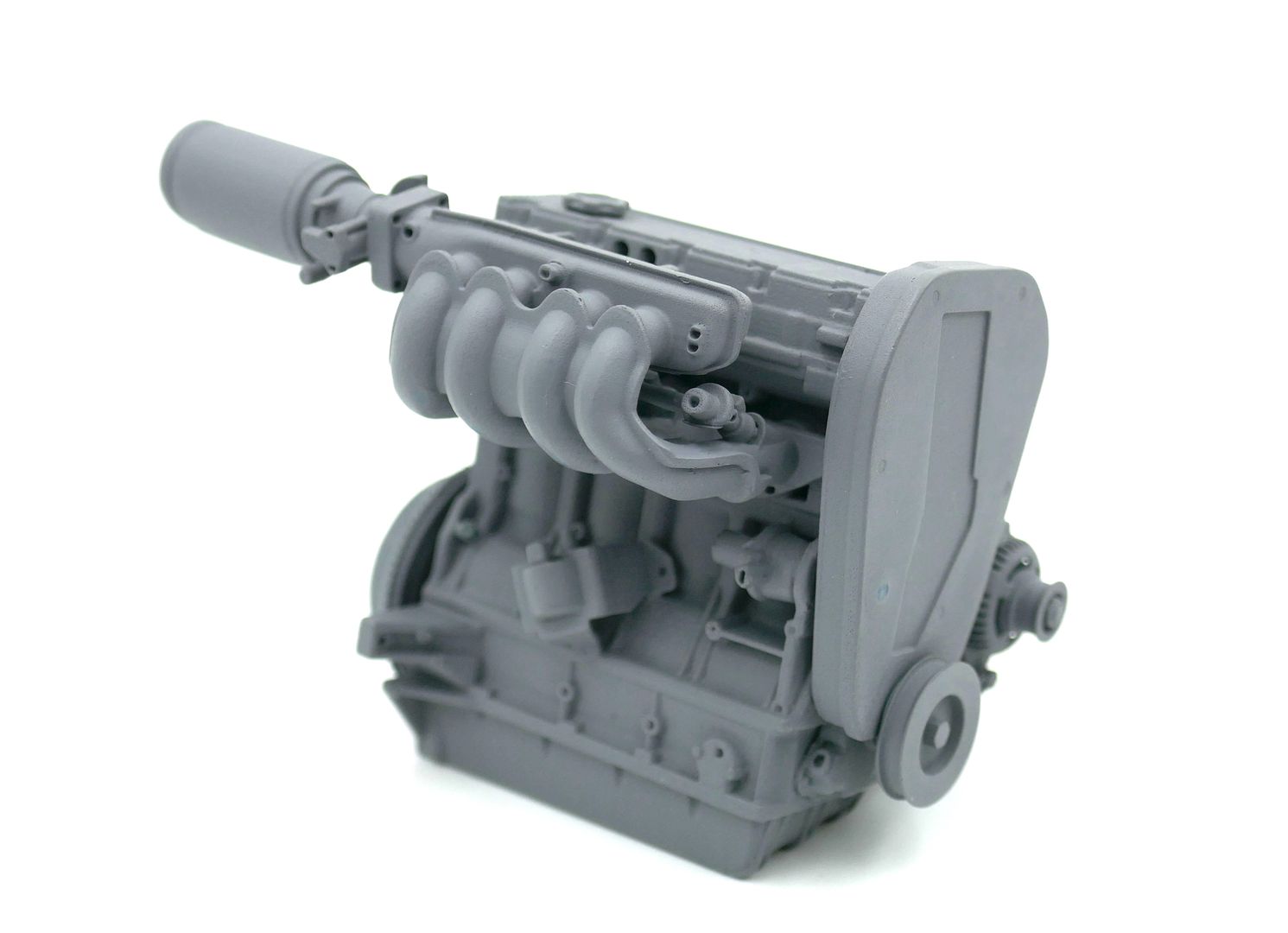
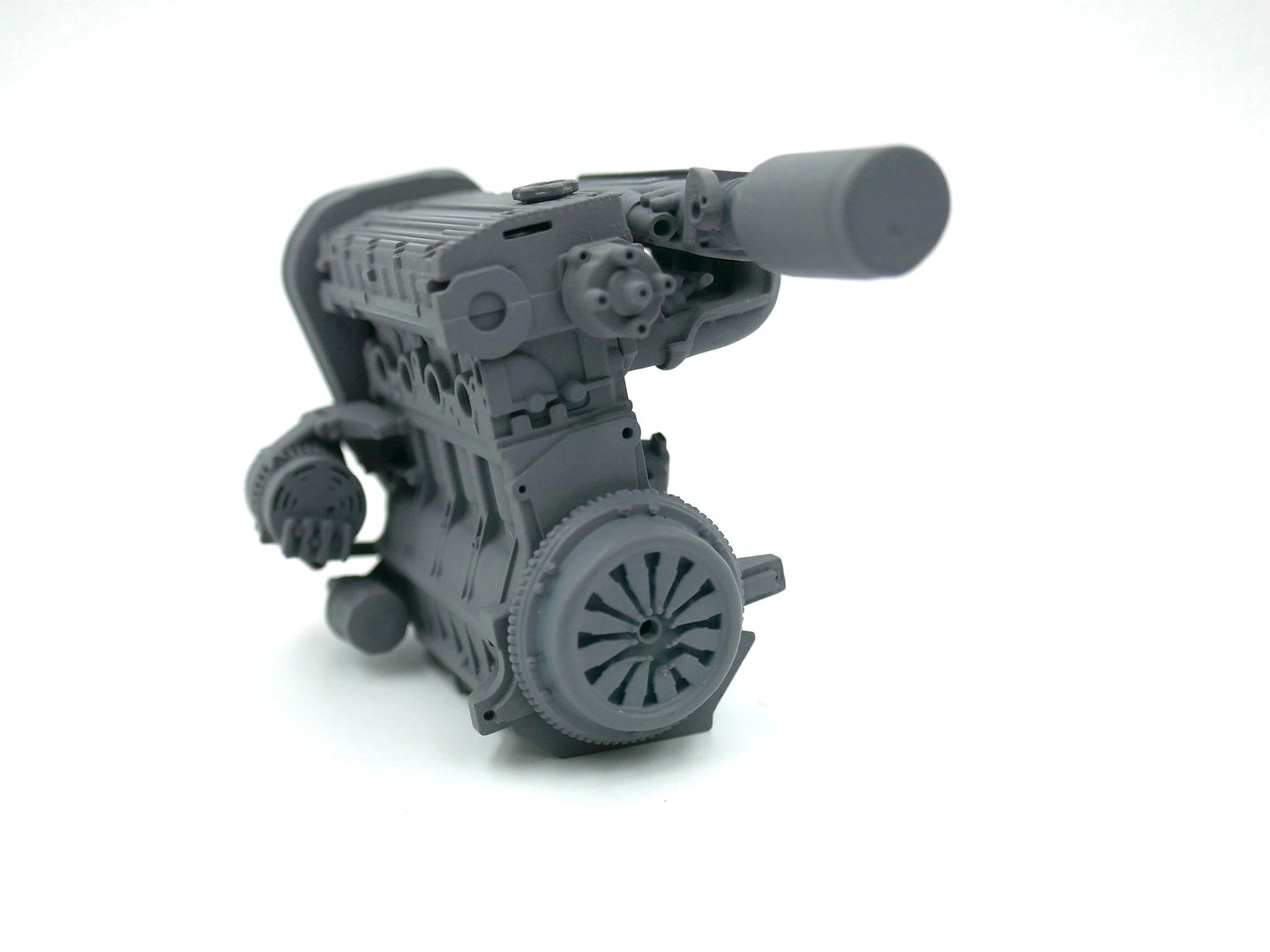
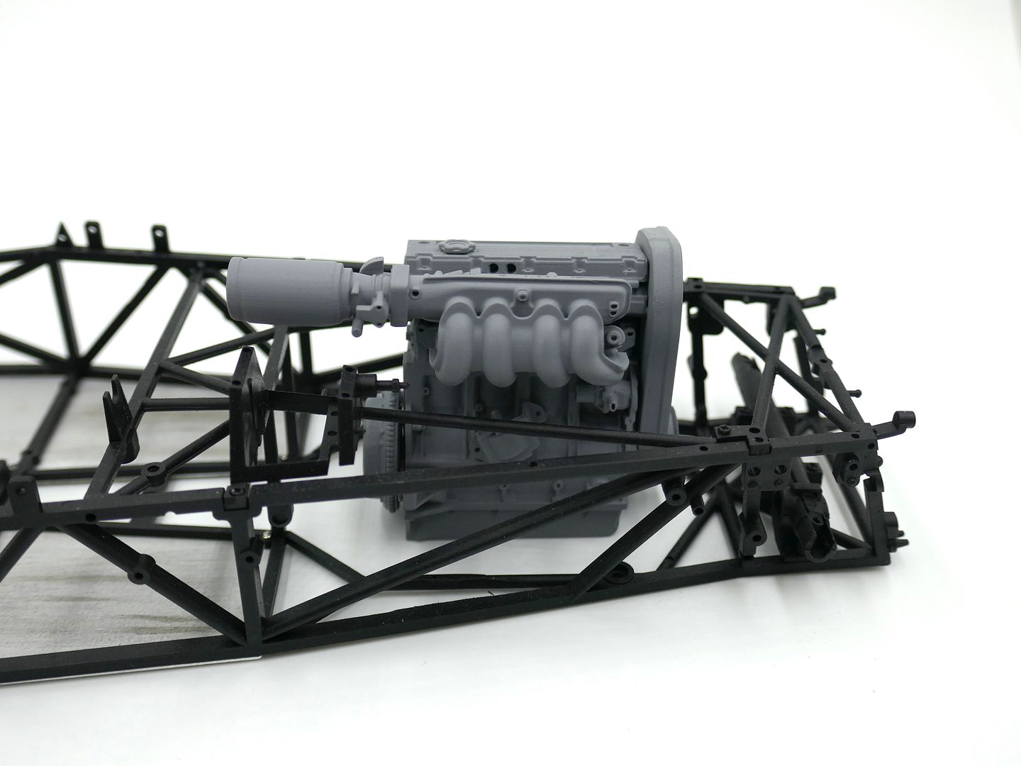
I'll have to move the engine mounts in the chassis!
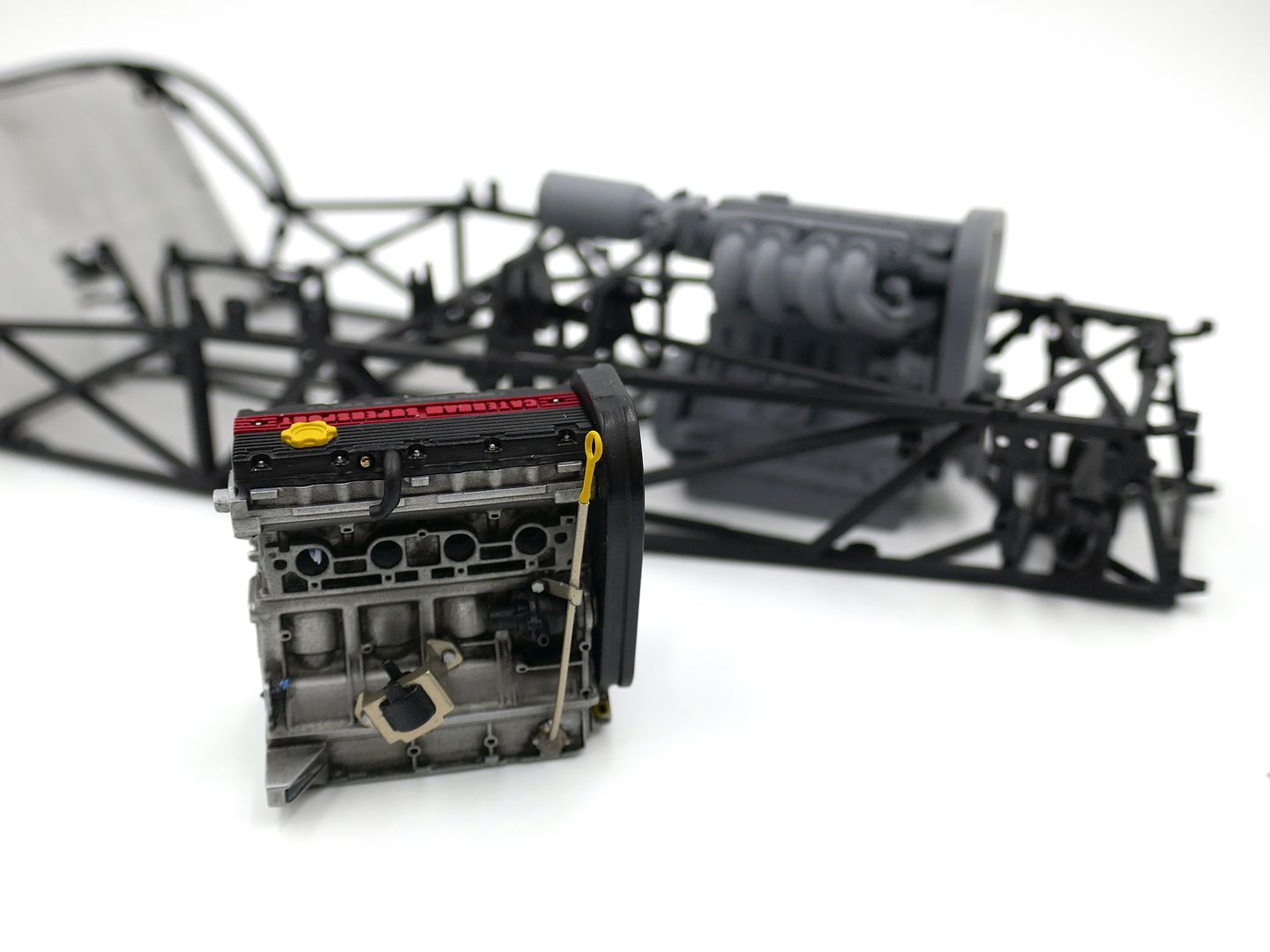
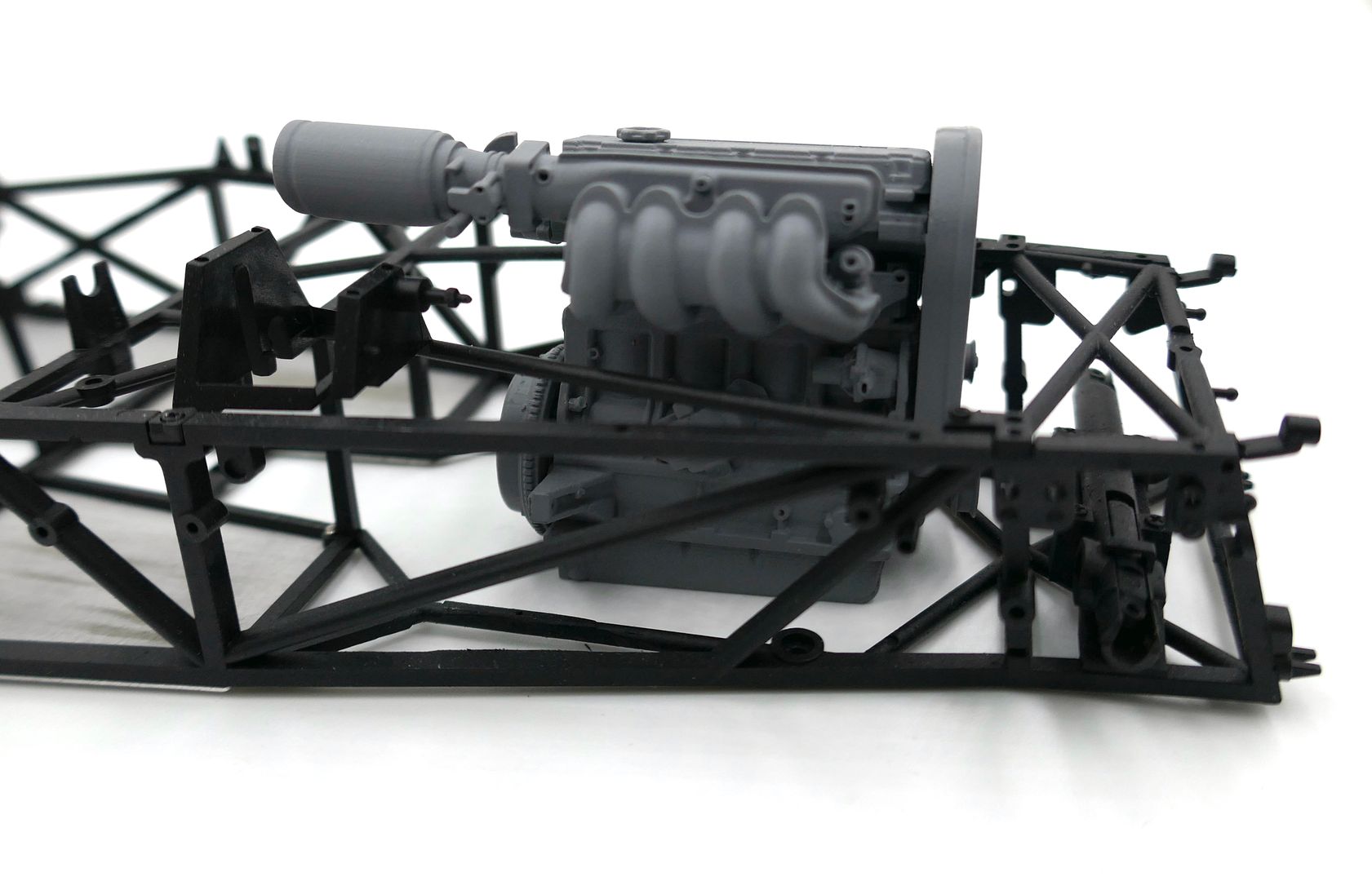
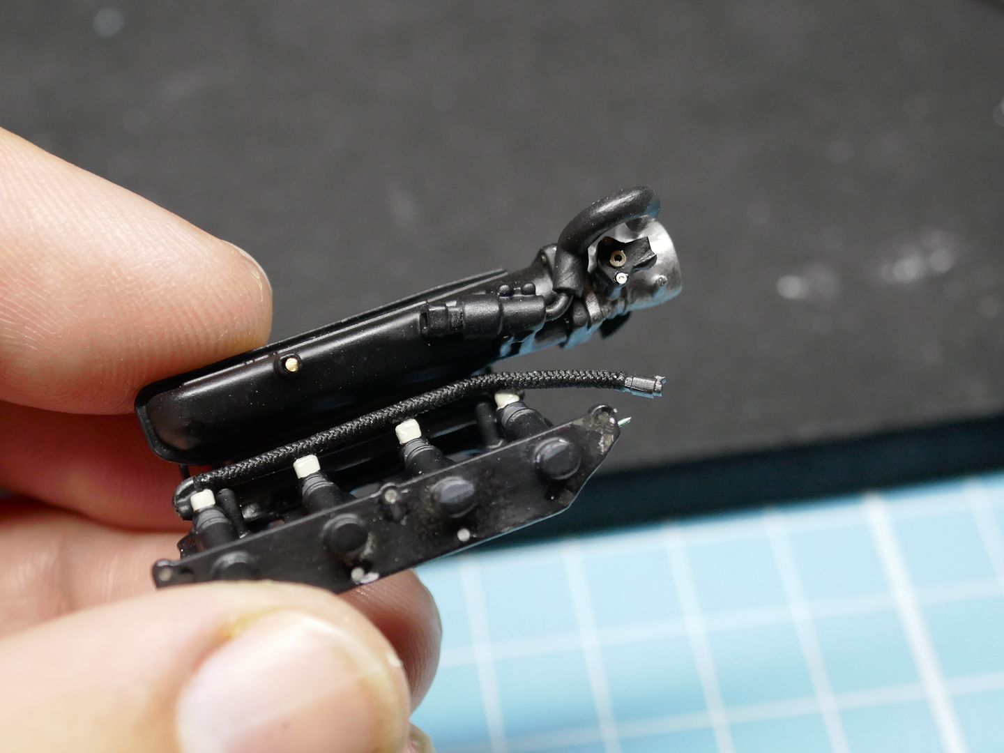
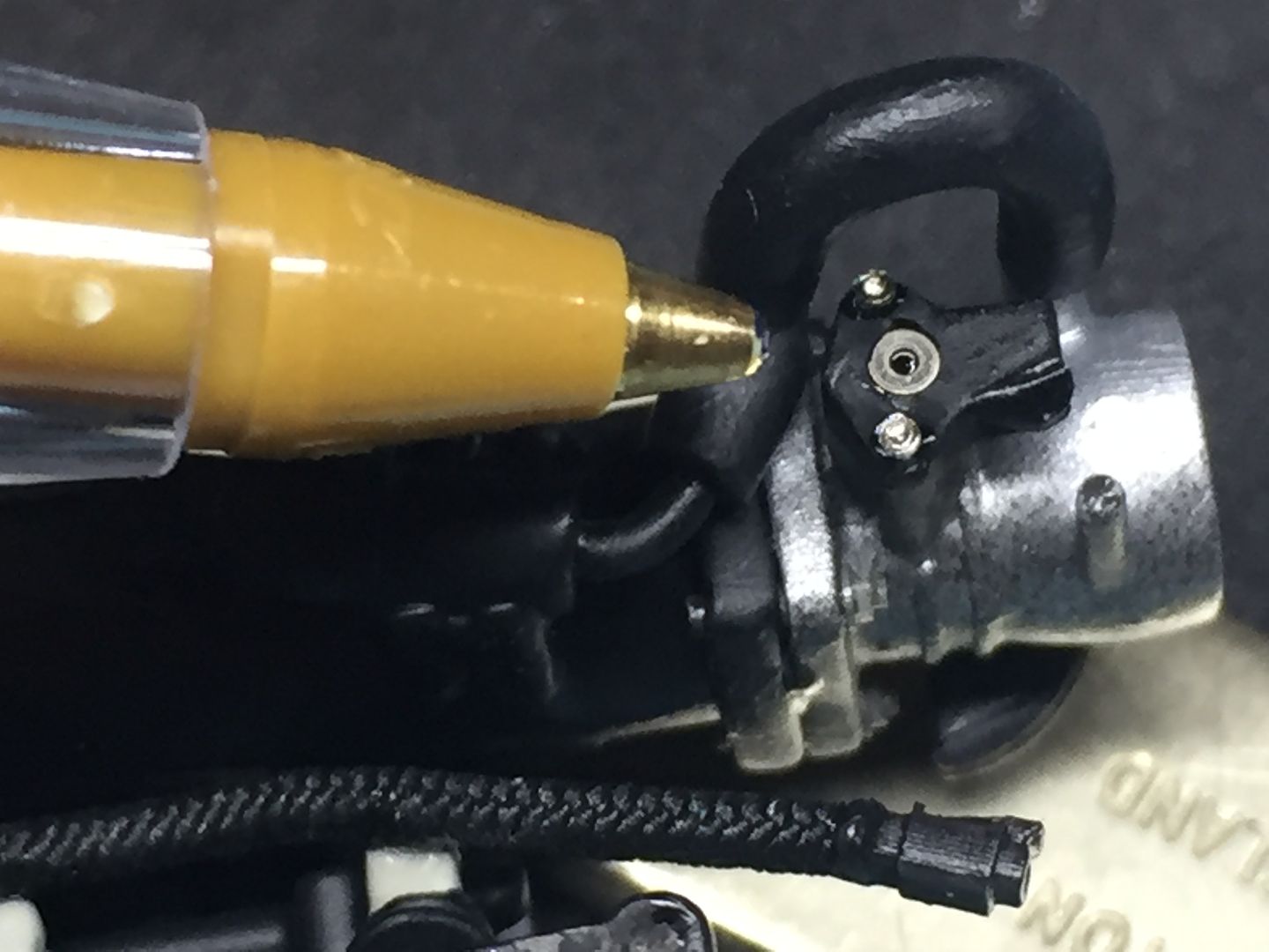
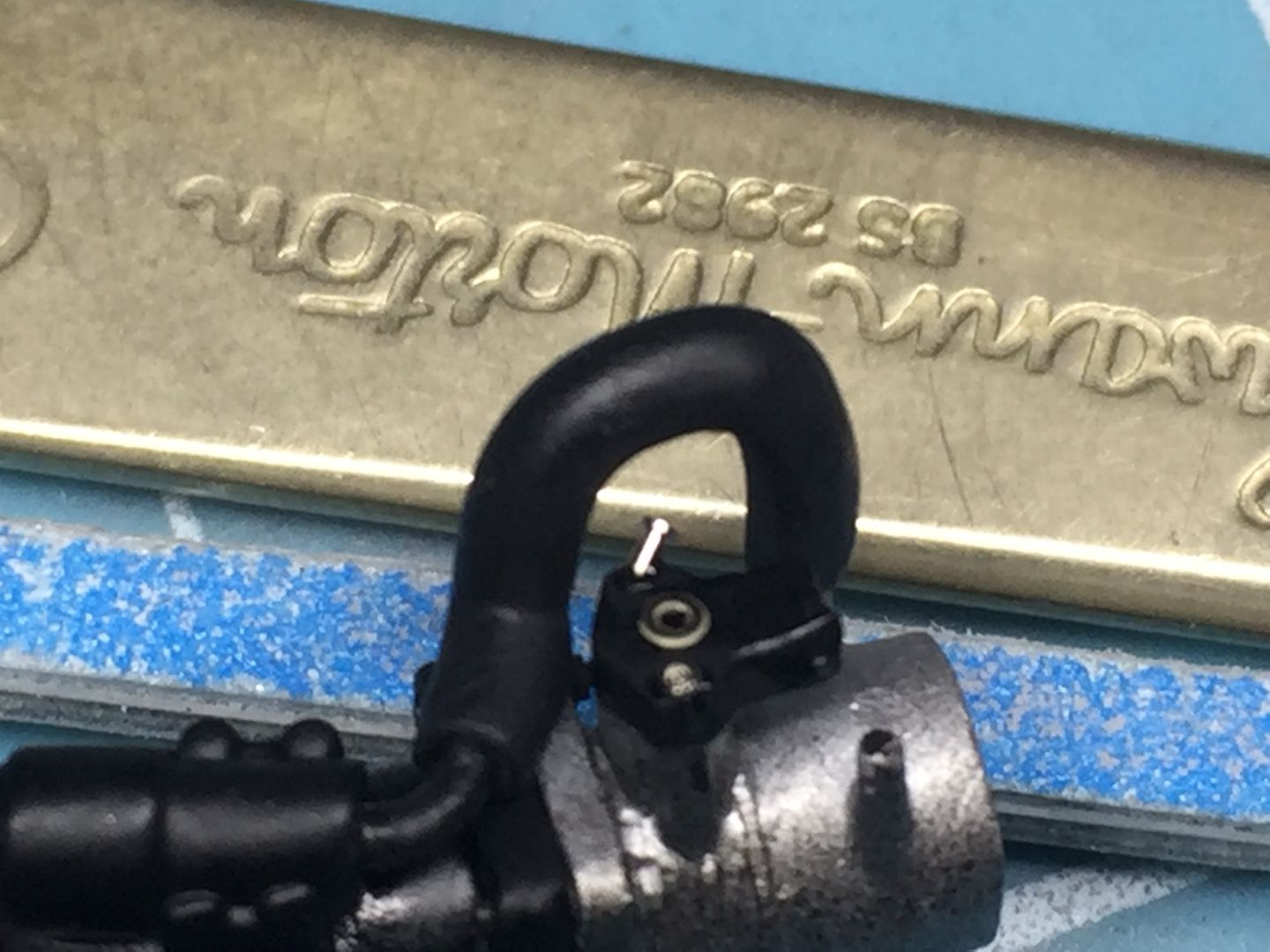
Painted the air intake black, and added some variation in terms of blacks for the injectors and fuel rail etc. None of this will ever be seen again once fitted to the engine!
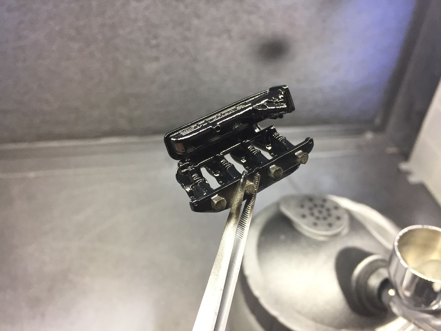
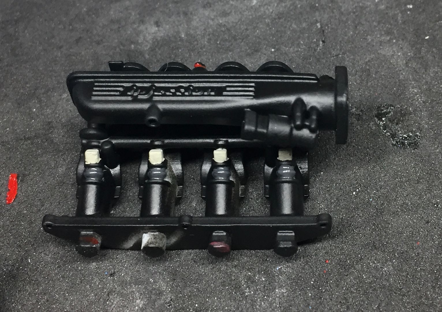
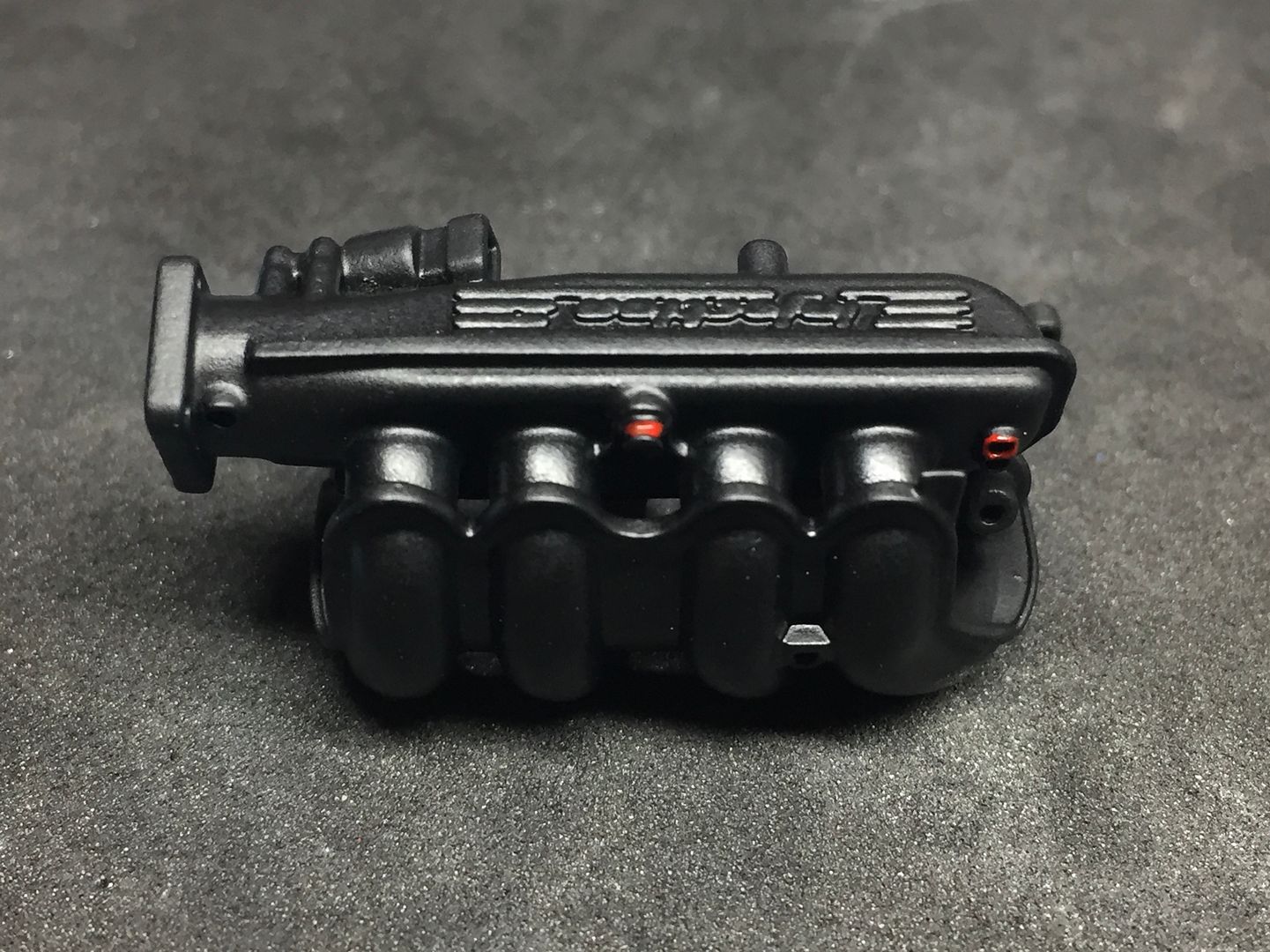
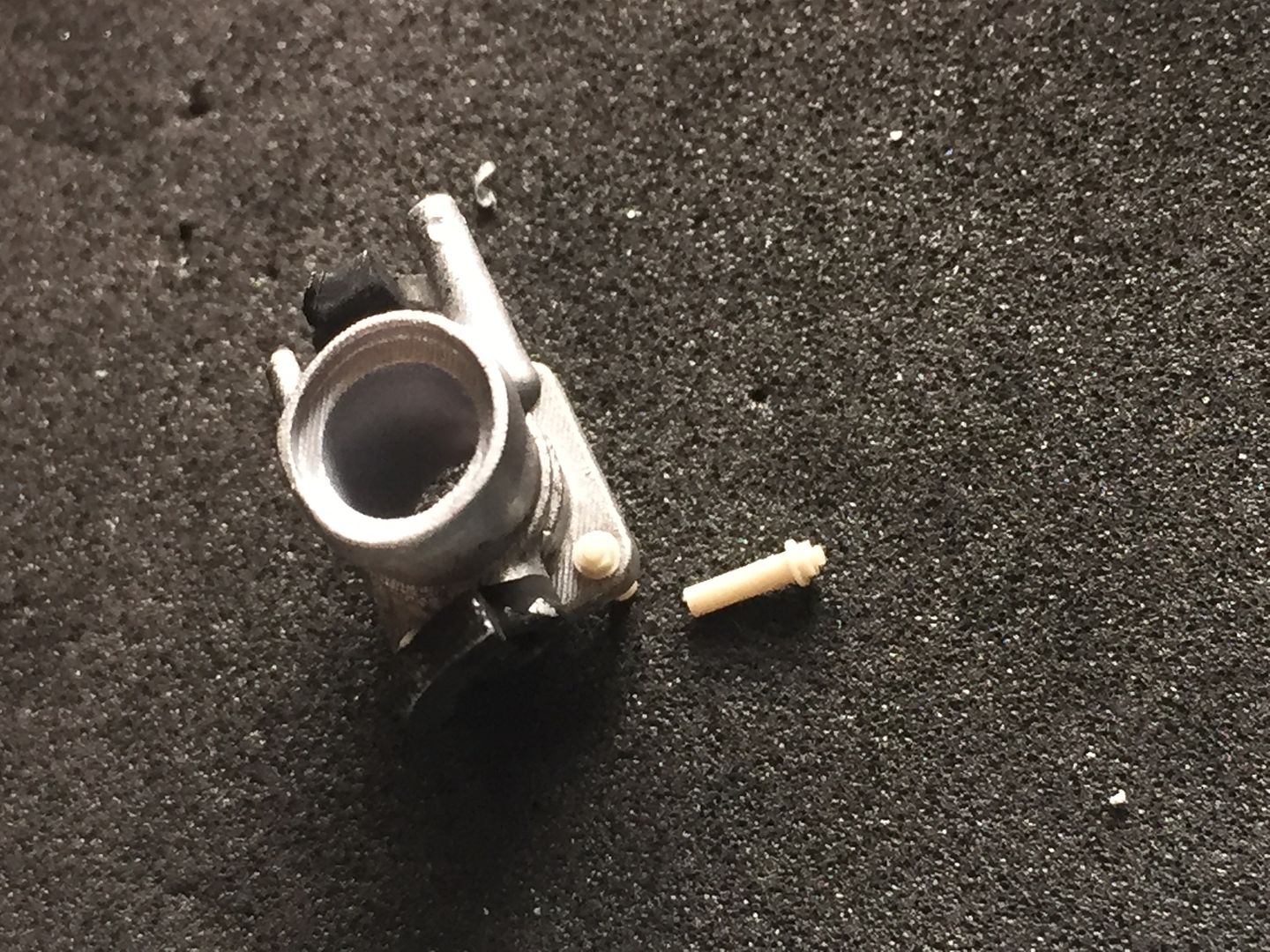
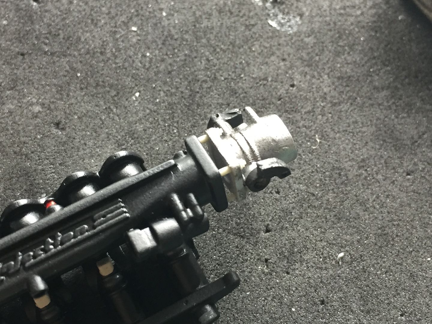
Bolting the throttle on...
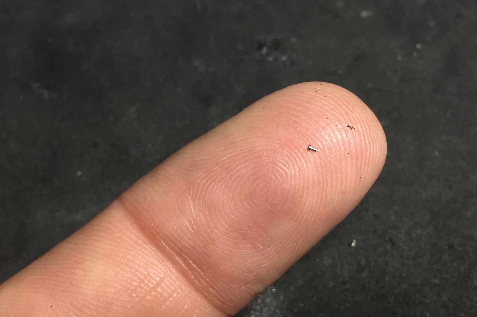
Rivet!
Holding the throttle pot on...(visually anyway)
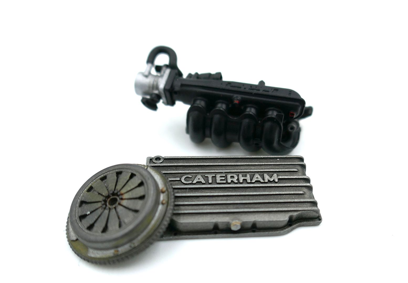
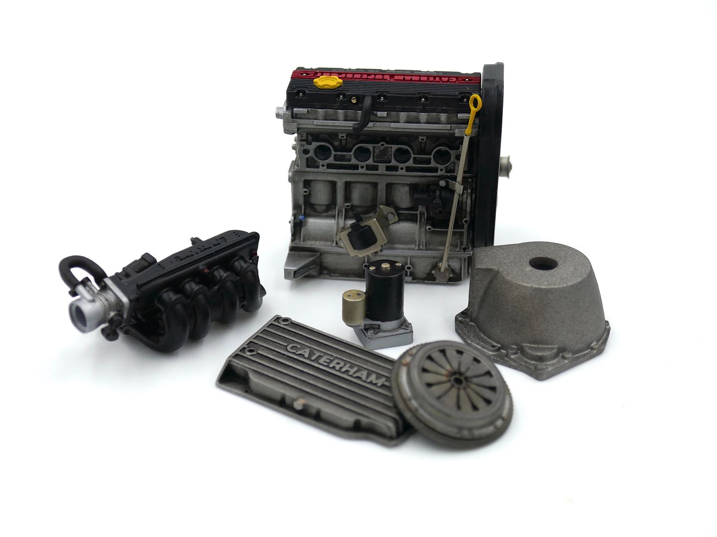
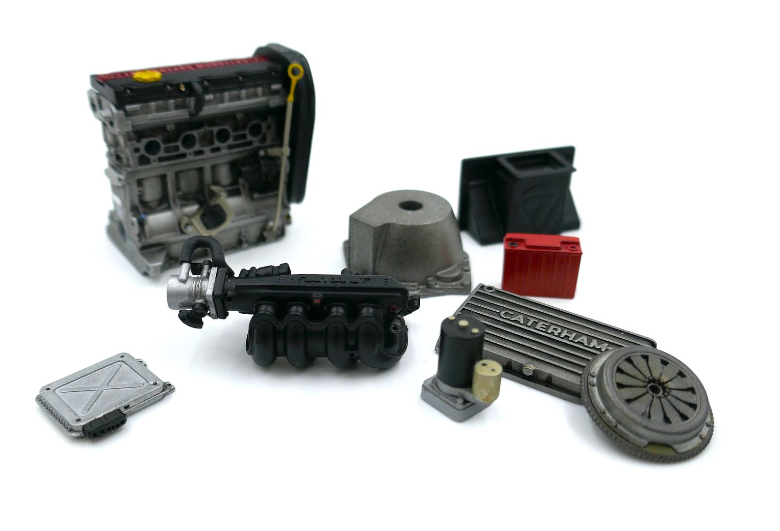
Gradually getting a kit of parts...
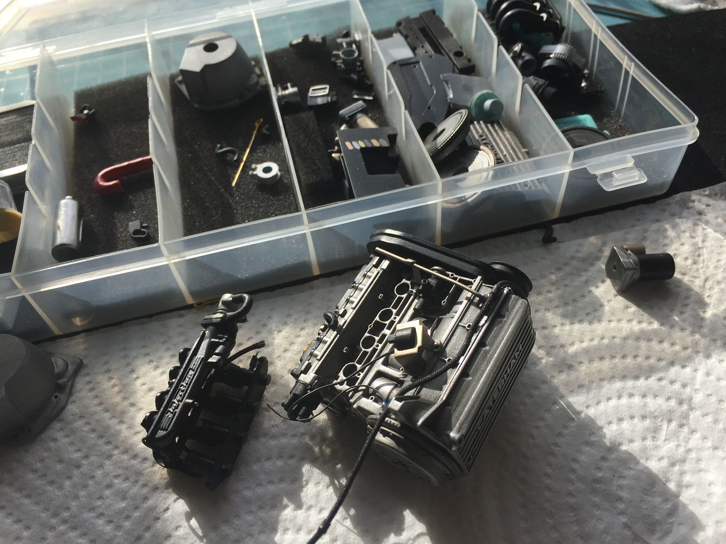
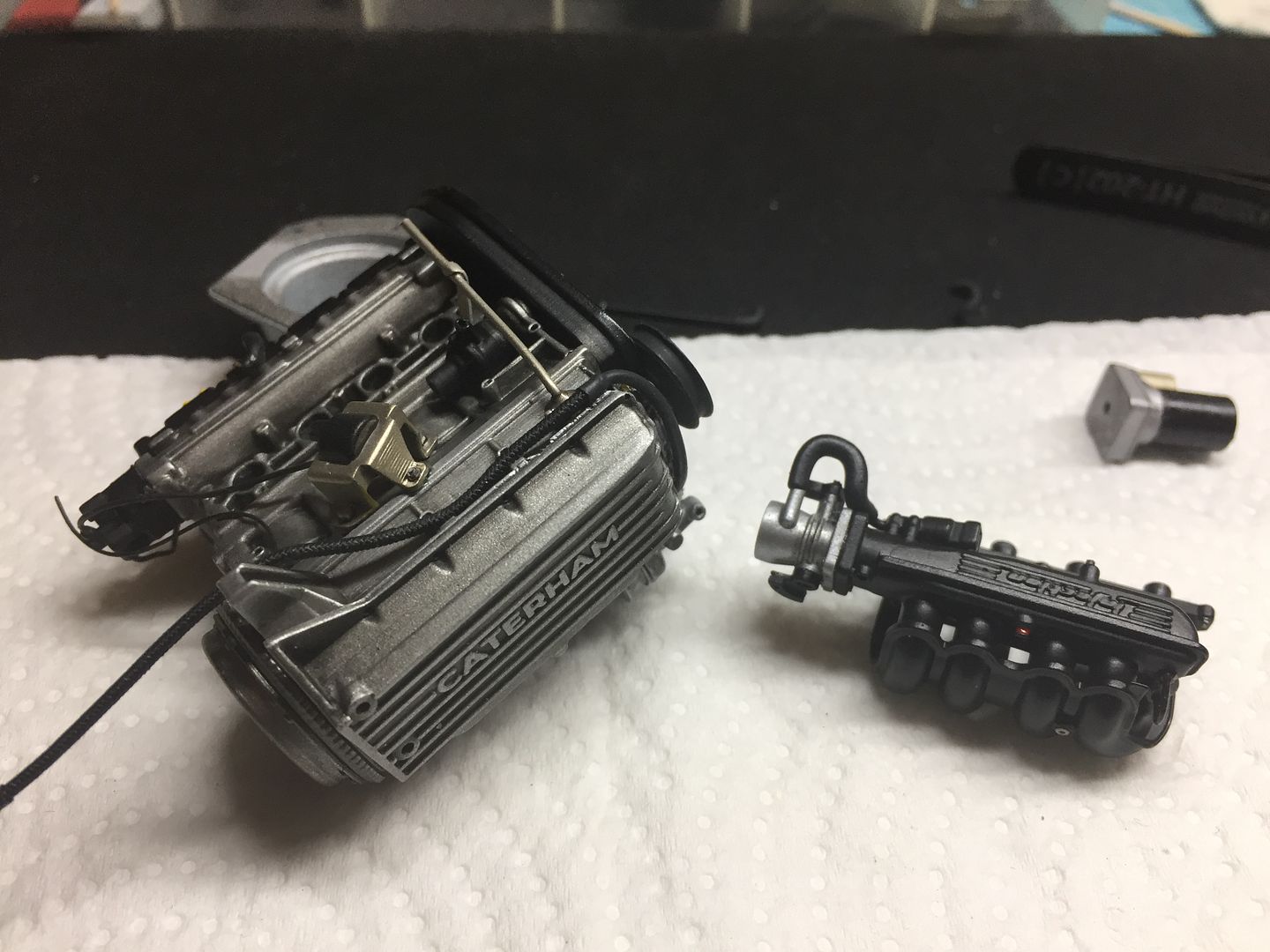
More wiring...
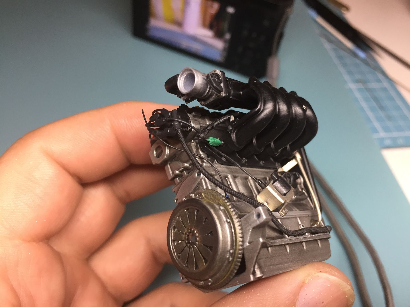
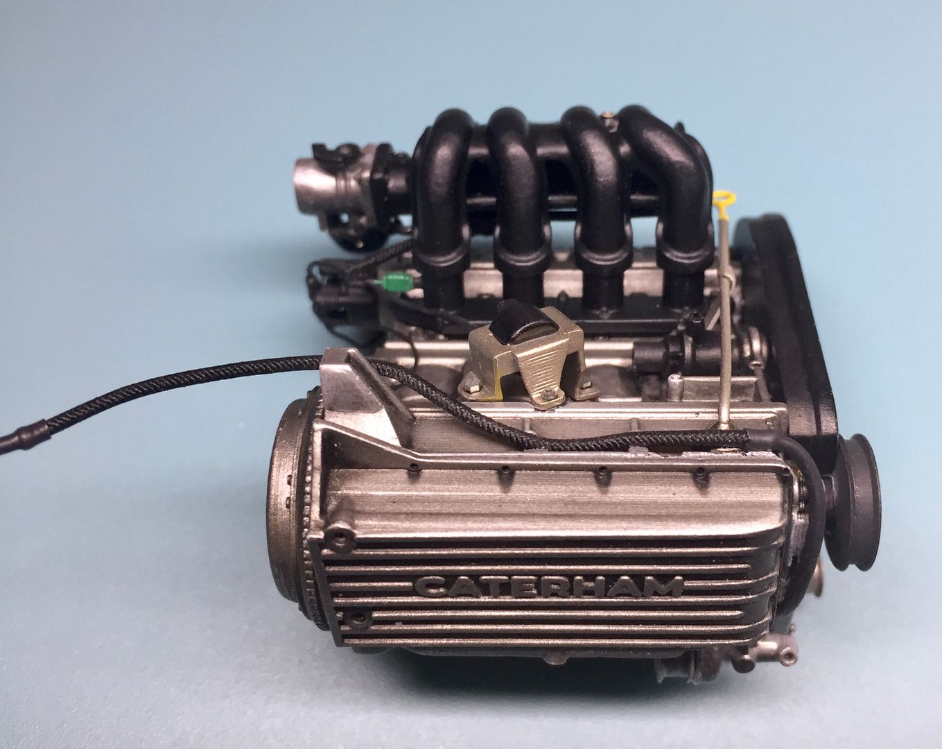
The braided hose is actually black elastic cord...

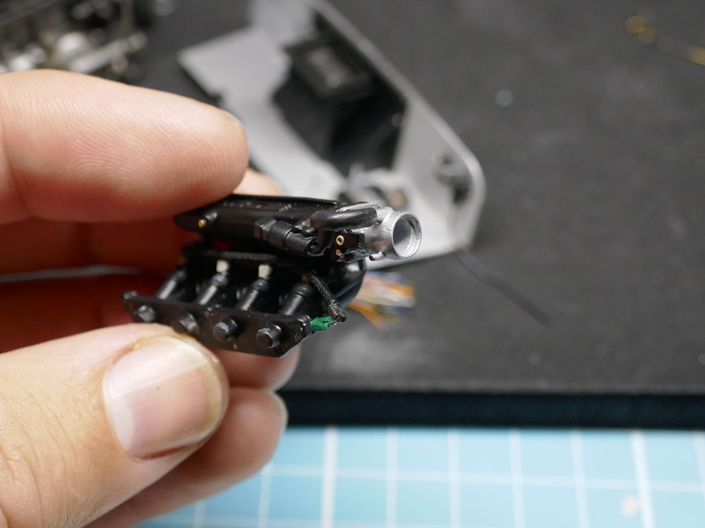
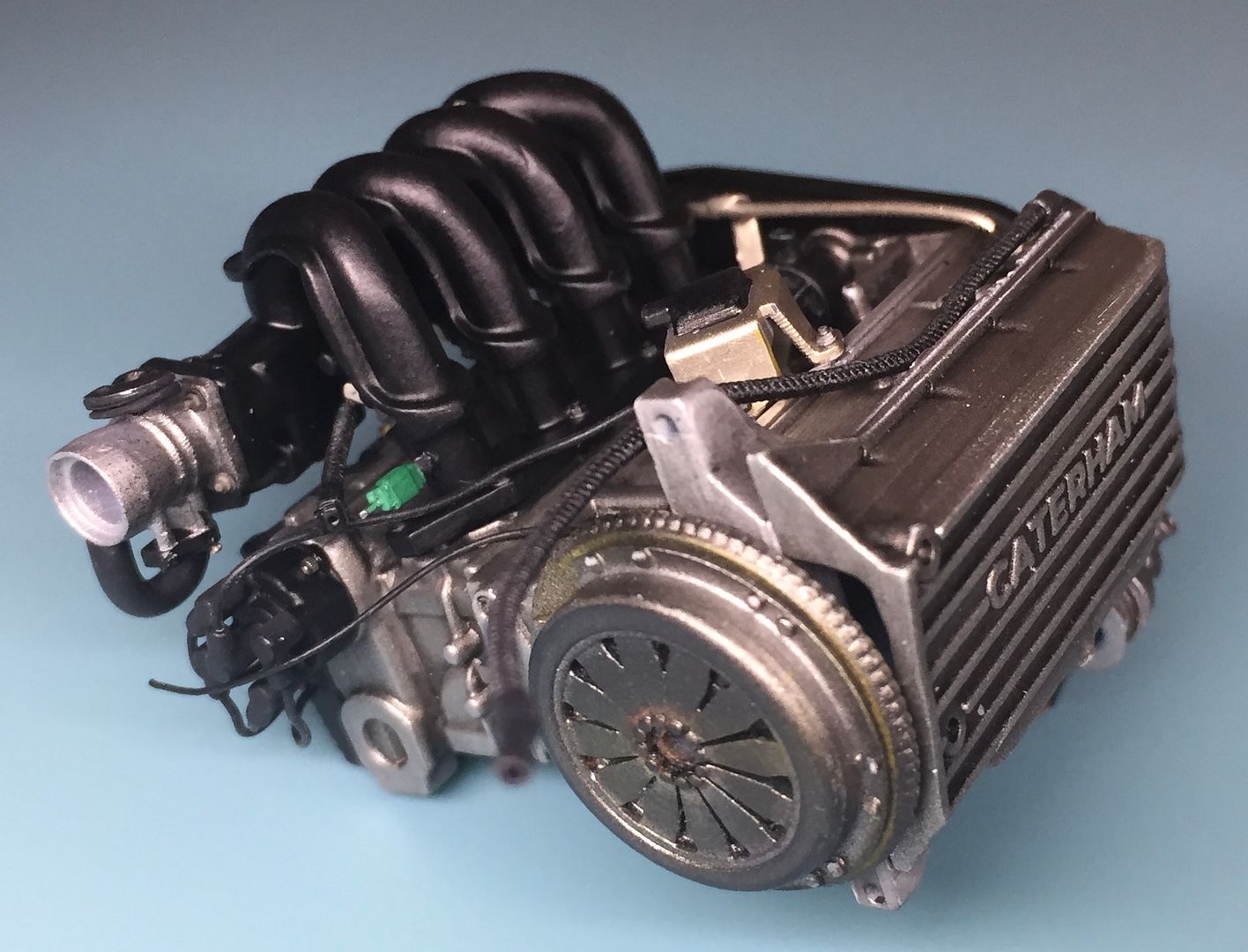
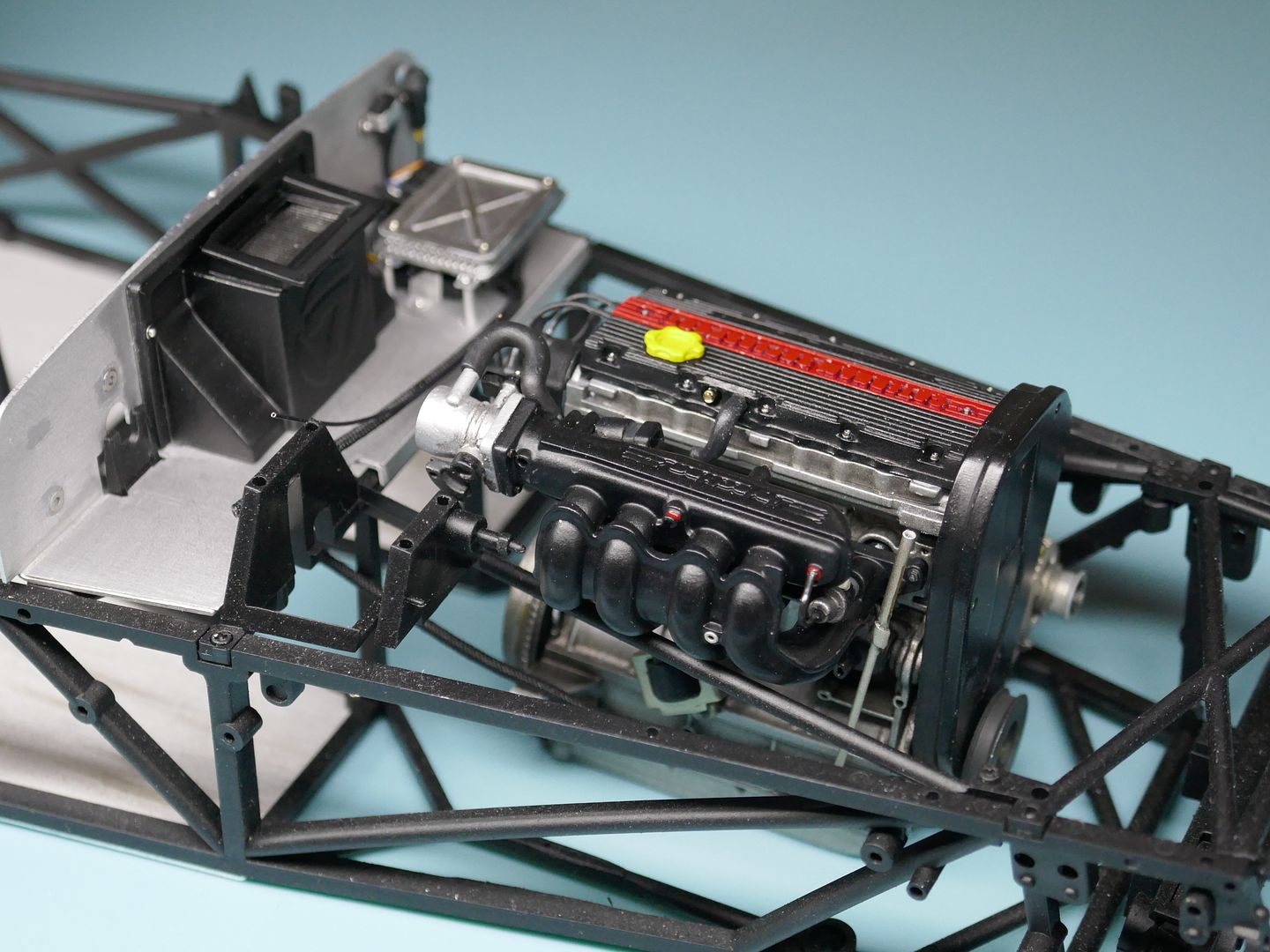
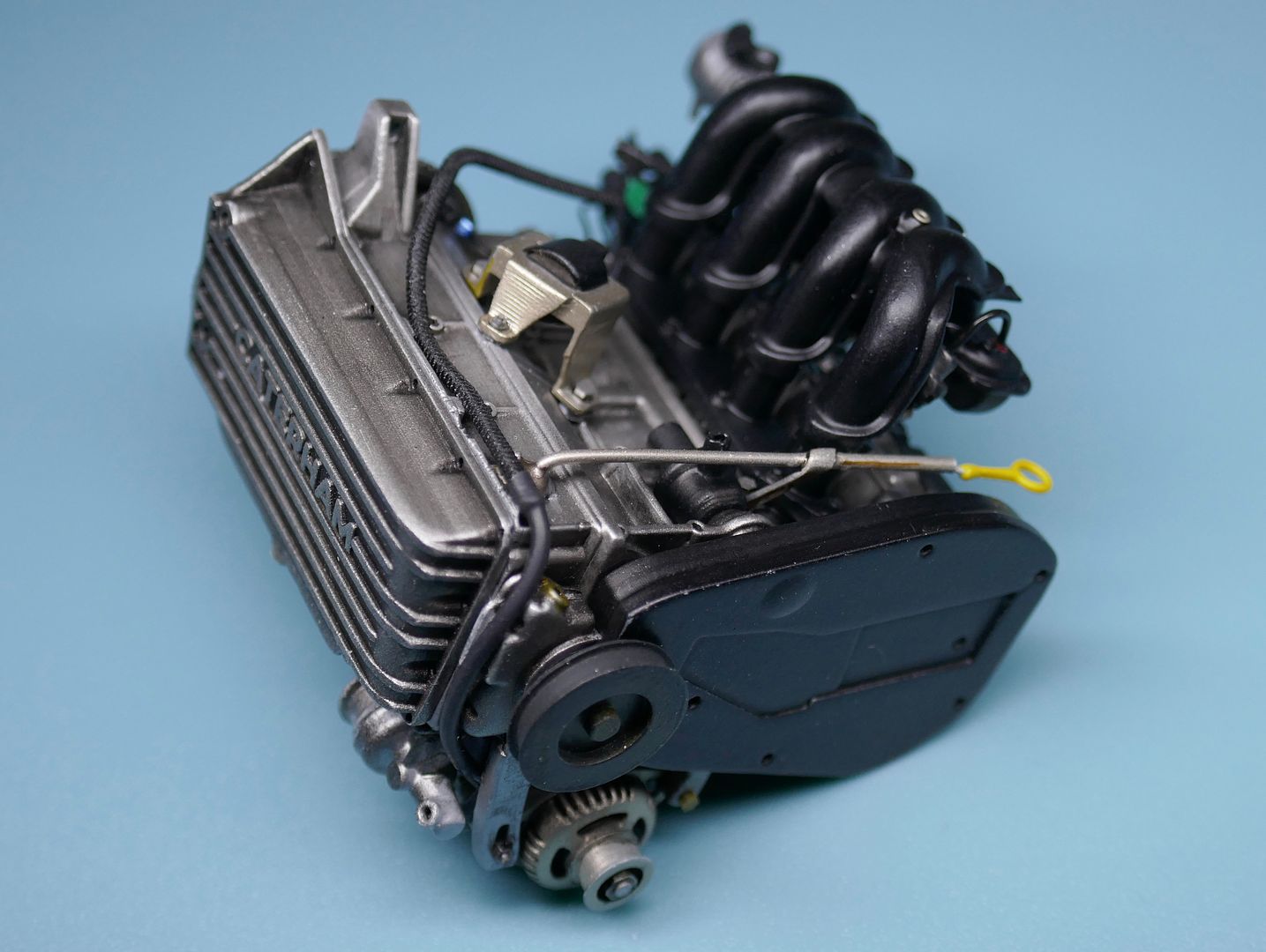
I printed some of the rubber hoses as solids for assembly, as the ones between the head and the air intake manifold actually help to hold them together, and bending rubber tube would have added too much strain...same with the ends of the HT leads - I actually printed them already on the distributor cap.
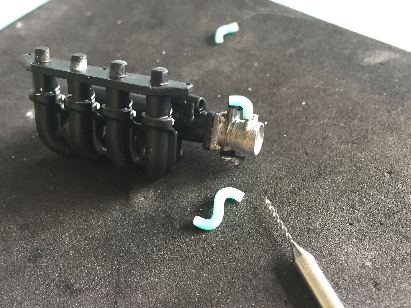
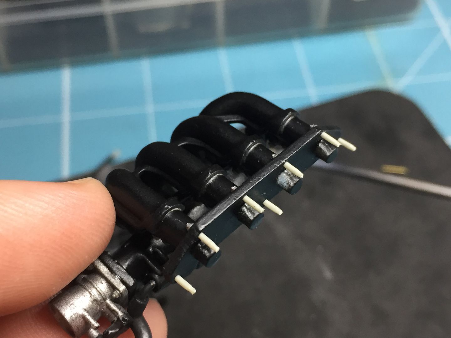
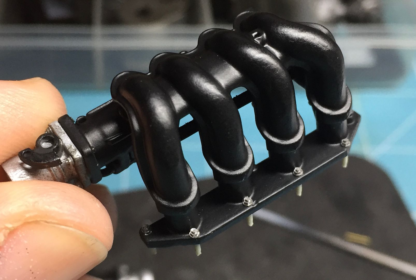
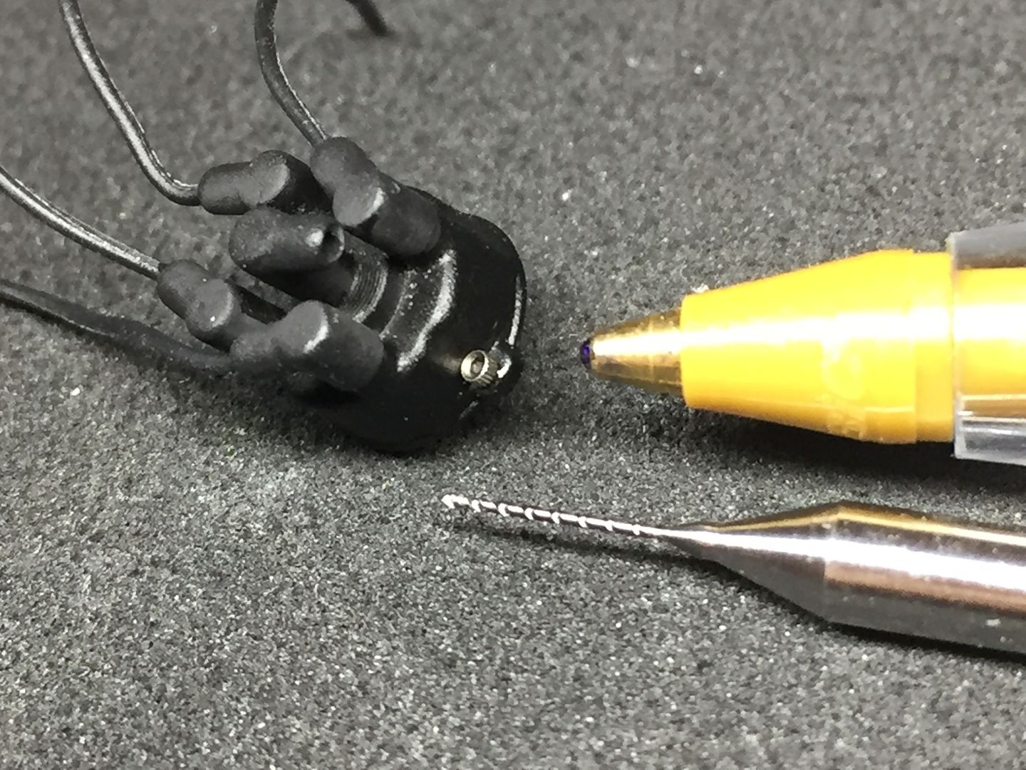
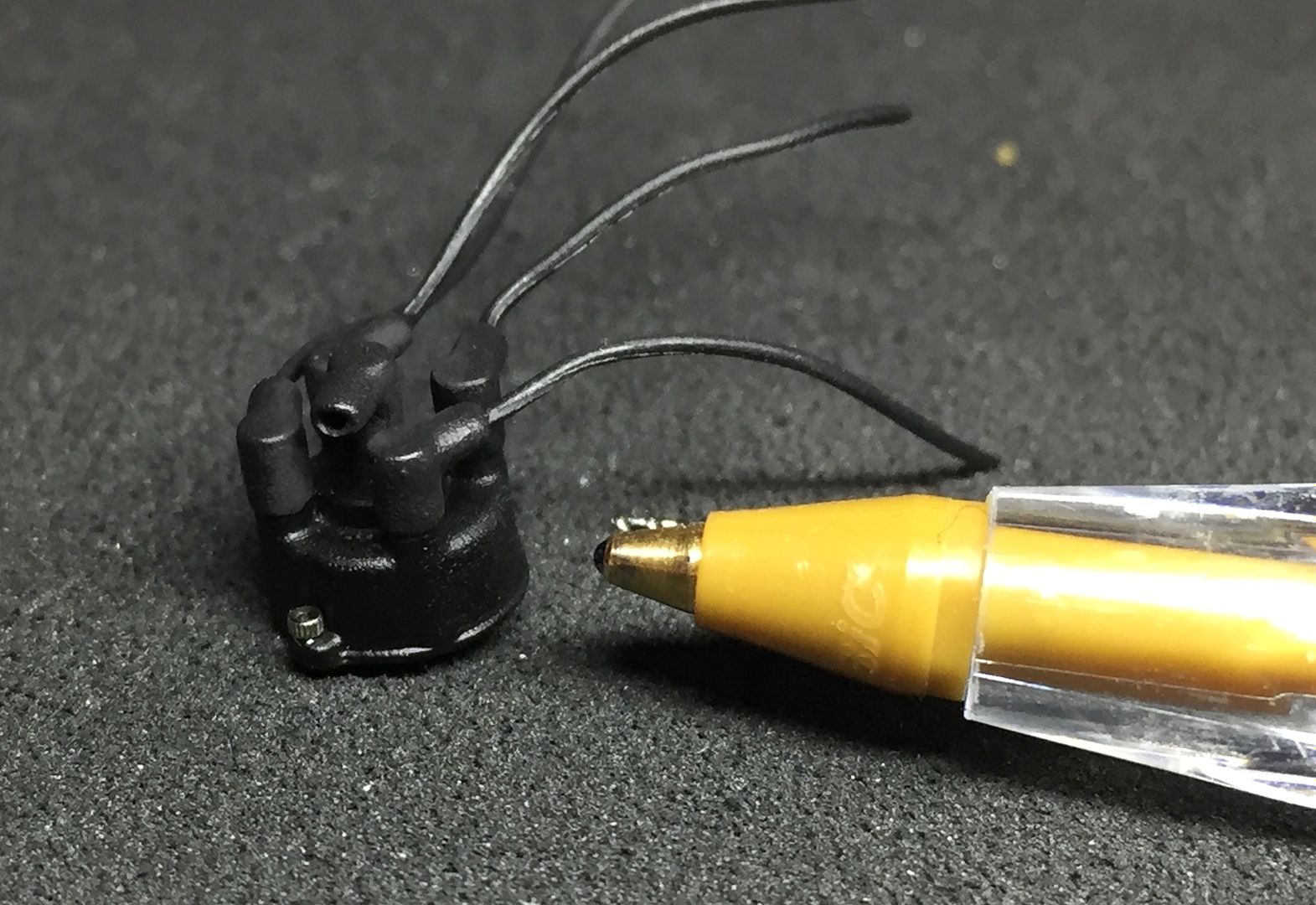
So that's where we are at this point!
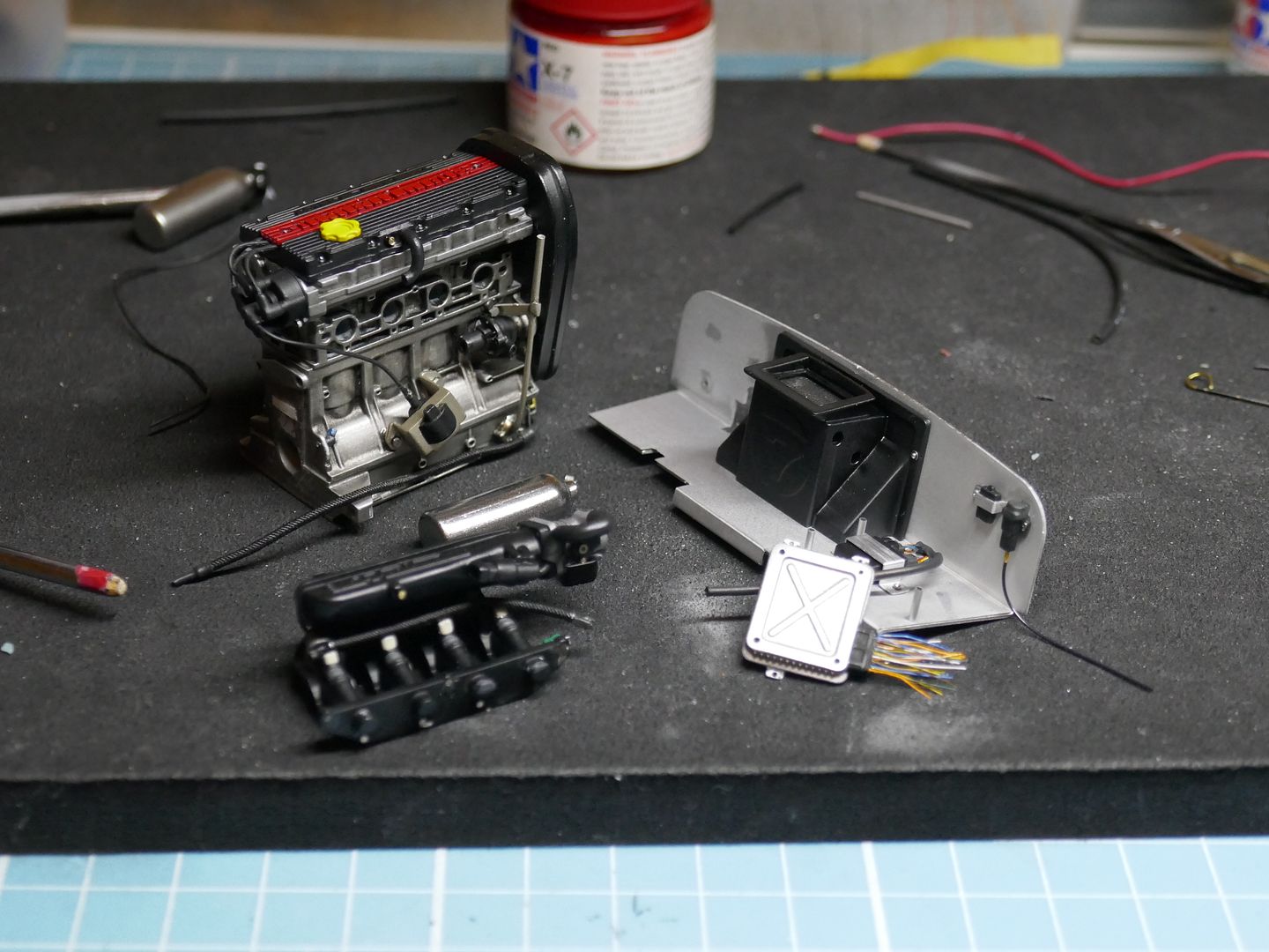
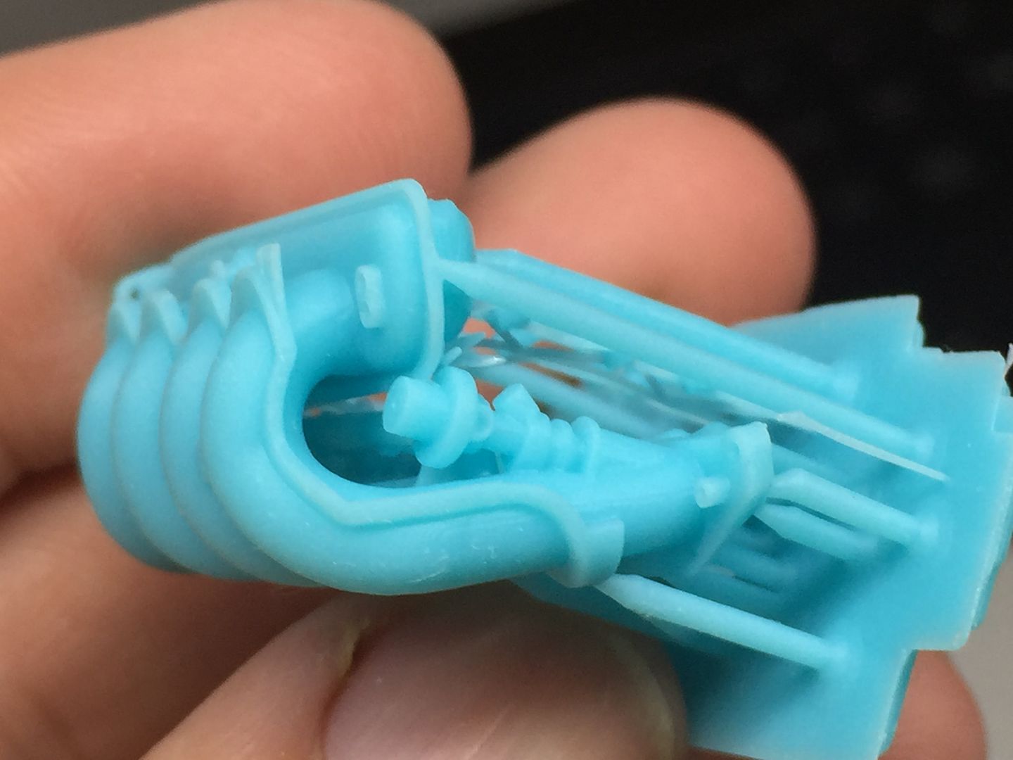
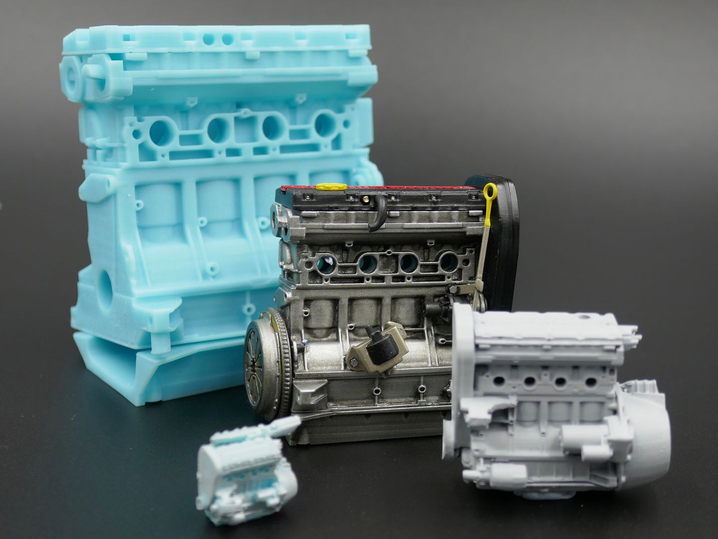
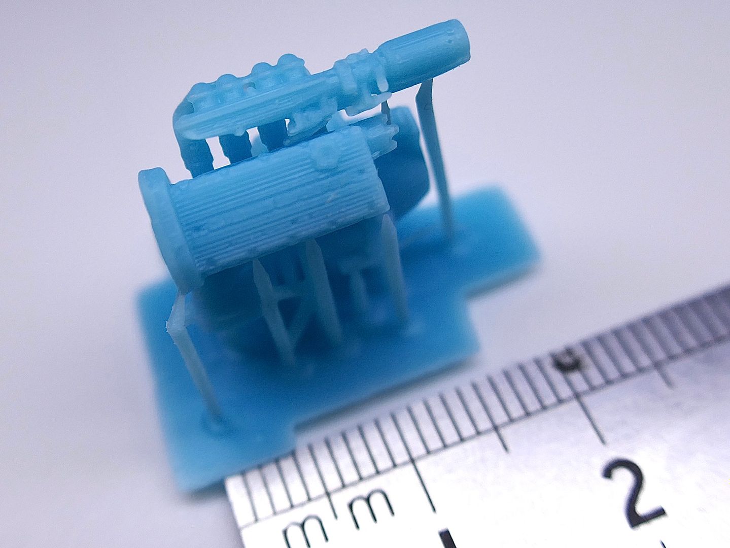
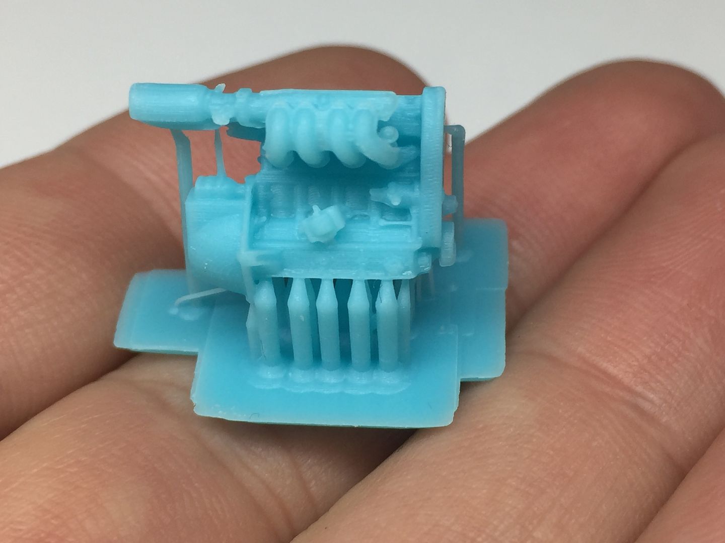
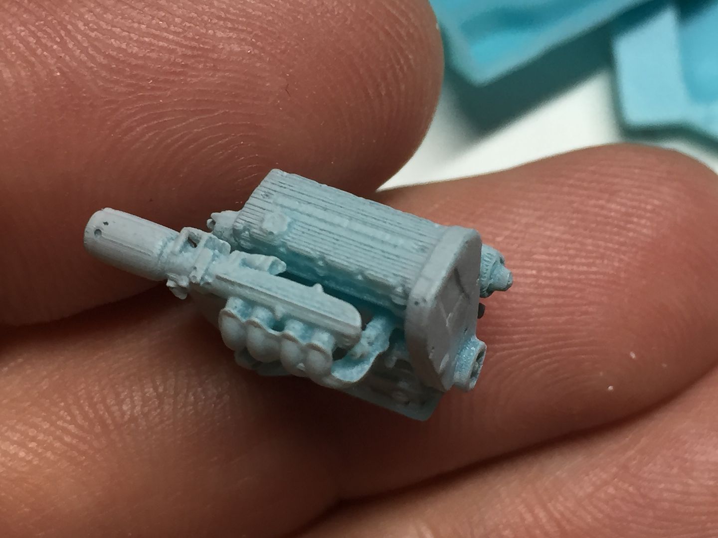
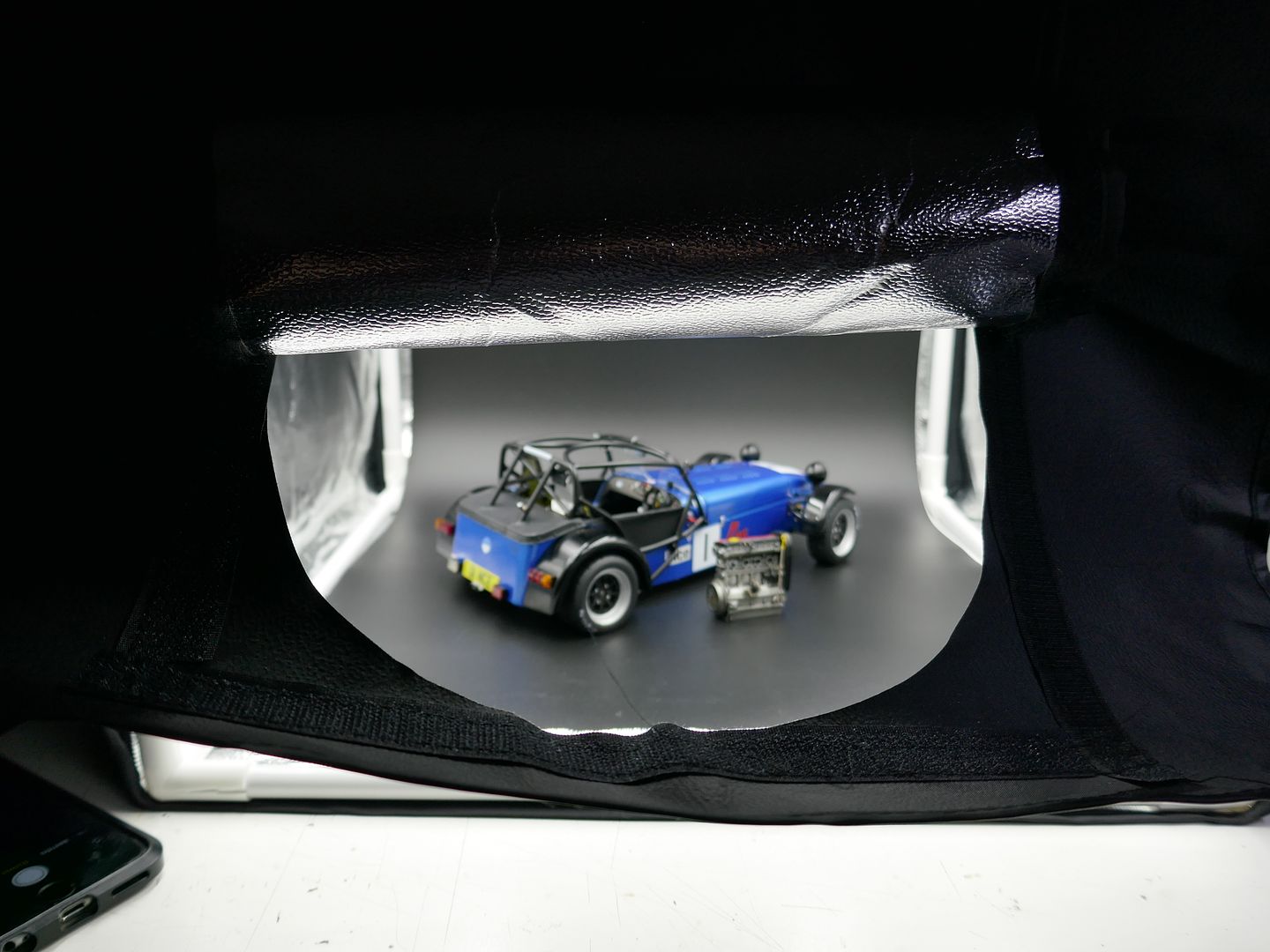
I printed some different scales for 'future projects' - Blue is 1/8th scale, painted is the 1/12 scale, grey is 1/18th for the Kyosho diecast Caterhams, and the tiny one is 1/43rd! That is 10mm across and I printed it whole to test - it would be assembled seperatley in the same way as the 1/12th - incrediable detail being picked out by the printer though...
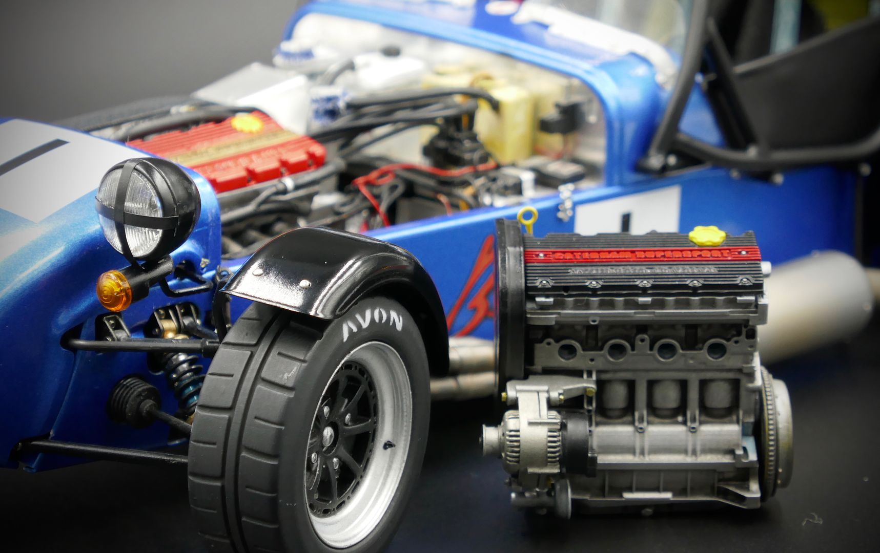
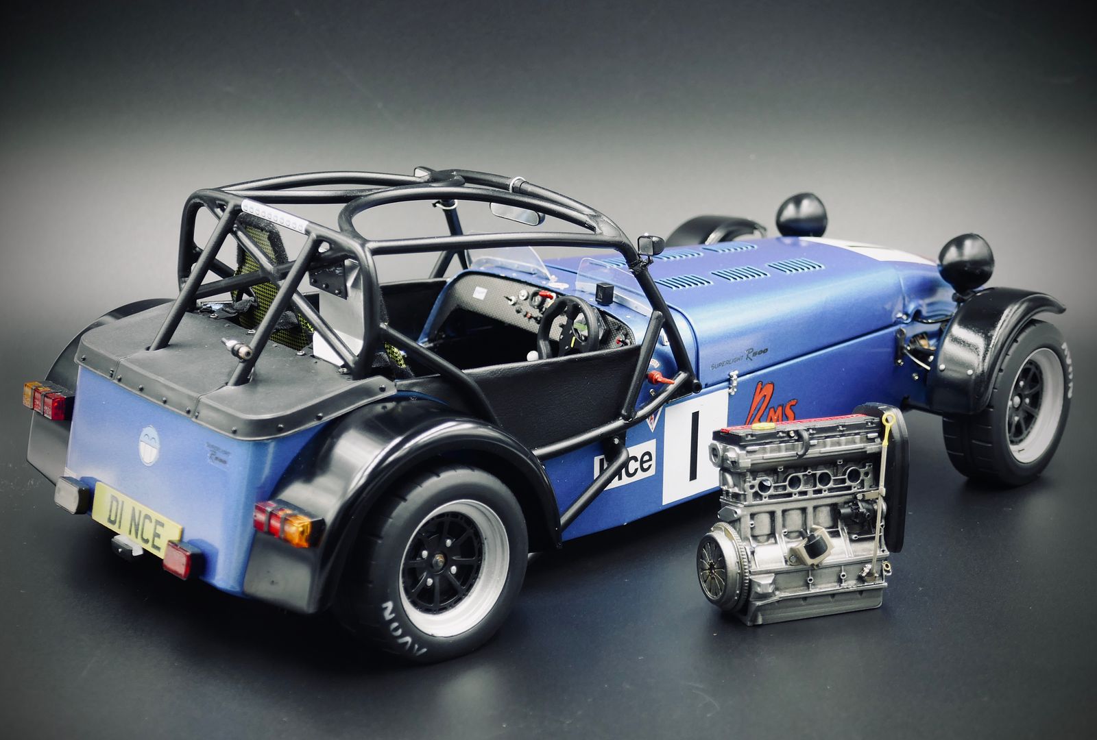
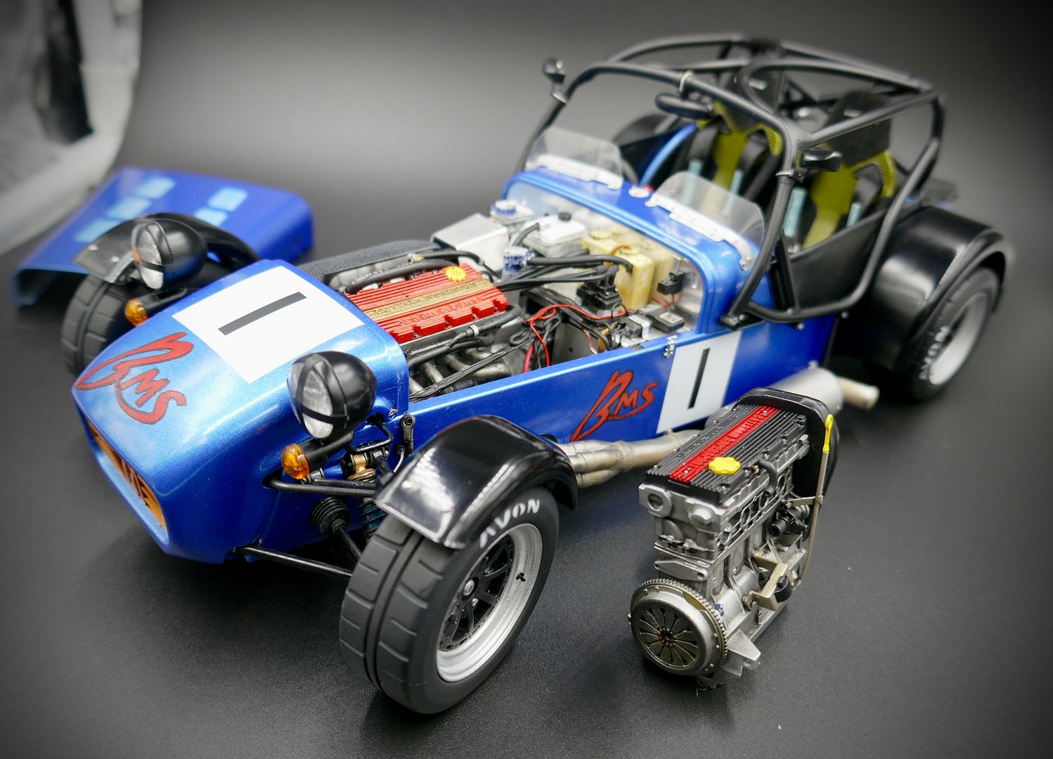
Before the R500's went, I managed to grab a few quick photos...

Brass and ali tubing for the dipstick tube, and I printed the 'handle' - another tiny part!


of course it 'works'....

So that was the main block sorted - the starter motor goes on after the bell housing...


You can see I have also started to add some wiring to the block.
But the next big bit to model was the air intake manifold. This was going to be a challenge in CAD for me, but managed it - best way to learn a program is a 'real' project! So the end result works, but it is by no means a 'good' CAD model! The splits involved made drawing and printing it more easily. The throttle is made separately and bolted together after painting, as will be the foam air filter.
I don't have this part on my car anymore, so had to rely on photos - although I was able to go and measure some bits halfway through the process - ebay and autofactors are good resources for parts pictures by the way...


Test print of the whole air intake assembly, to check fit and scale etc


Lots of test prints to find the best orientation etc


At this point I glued all the bits together and primed one version, just to get a clear overall view, and again, to test fit!


I'll have to move the engine mounts in the chassis!


Painted the air intake black, and added some variation in terms of blacks for the injectors and fuel rail etc. None of this will ever be seen again once fitted to the engine!


Bolting the throttle on...


Rivet!

Holding the throttle pot on...(visually anyway)


Gradually getting a kit of parts...


More wiring...


The braided hose is actually black elastic cord...


I printed some of the rubber hoses as solids for assembly, as the ones between the head and the air intake manifold actually help to hold them together, and bending rubber tube would have added too much strain...same with the ends of the HT leads - I actually printed them already on the distributor cap.


So that's where we are at this point!

I printed some different scales for 'future projects'
 - Blue is 1/8th scale, painted is the 1/12 scale, grey is 1/18th for the Kyosho diecast Caterhams, and the tiny one is 1/43rd! That is 10mm across and I printed it whole to test - it would be assembled seperatley in the same way as the 1/12th - incrediable detail being picked out by the printer though...


Before the R500's went, I managed to grab a few quick photos...


Back to the chassis:
I fitted the suspension, front and rear. Nothing much to change on the kit at this point - it is pretty spot on - I tweak the wheel track slightly with the hubs at a later point. The layout and geometry is spot on, and you can actually change the 'set-up' and see the changes if you fiddle with the trailing arms and de-dion tube - I need to video it sometime in the future!
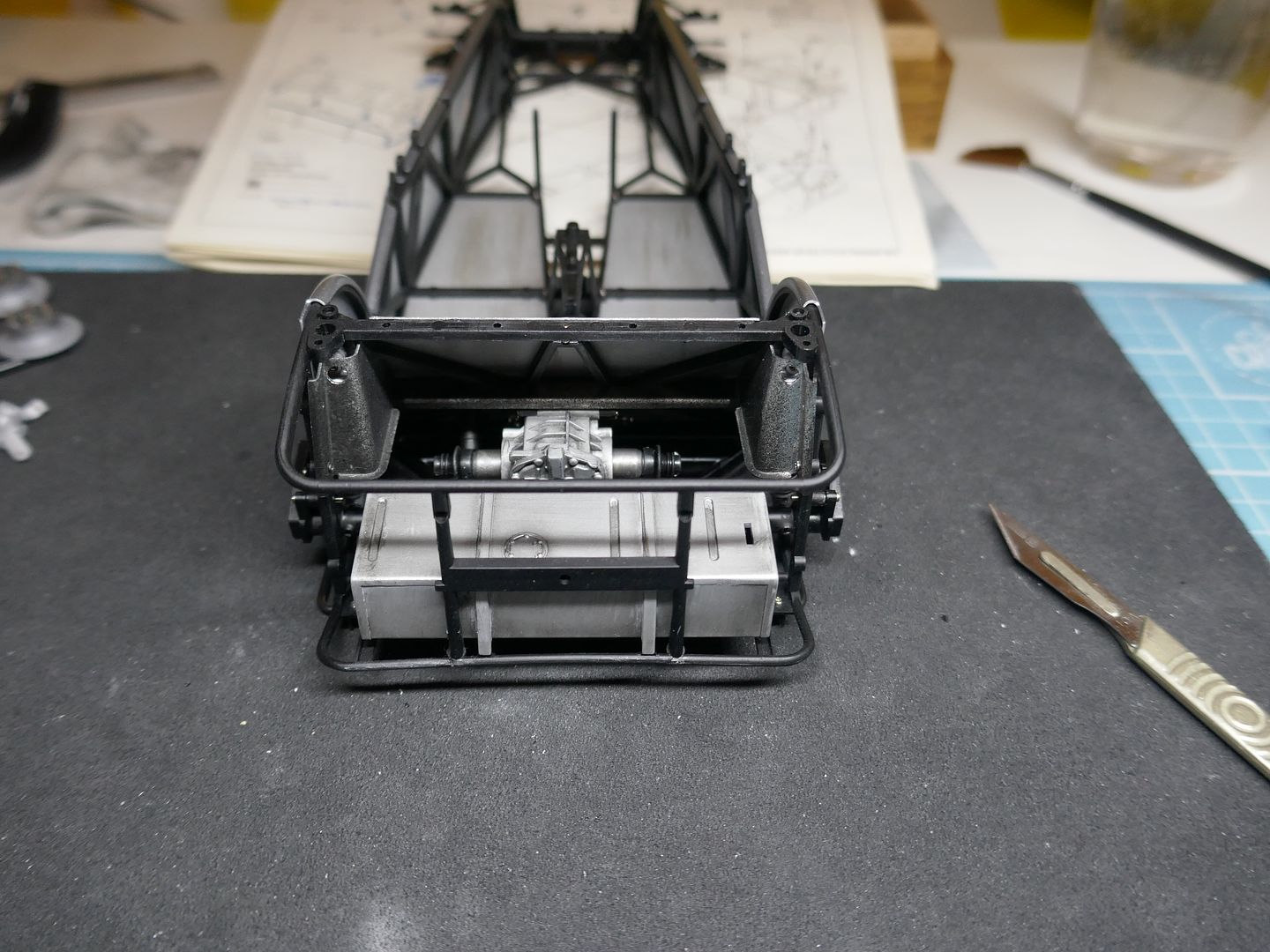
I also painted and fitted the diff and the fuel tank....
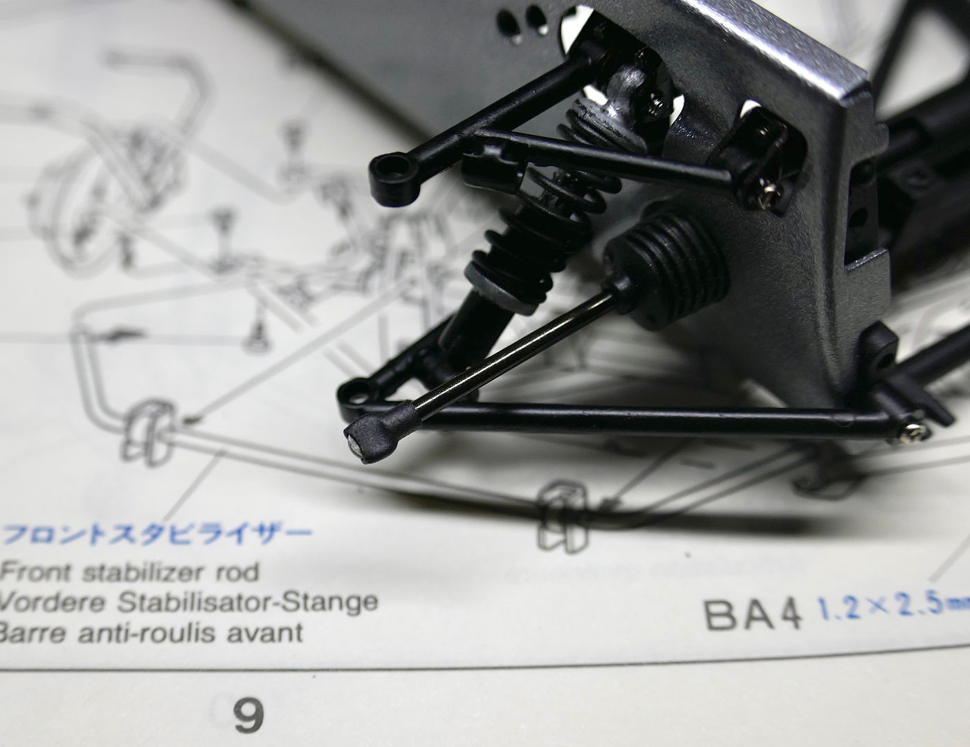
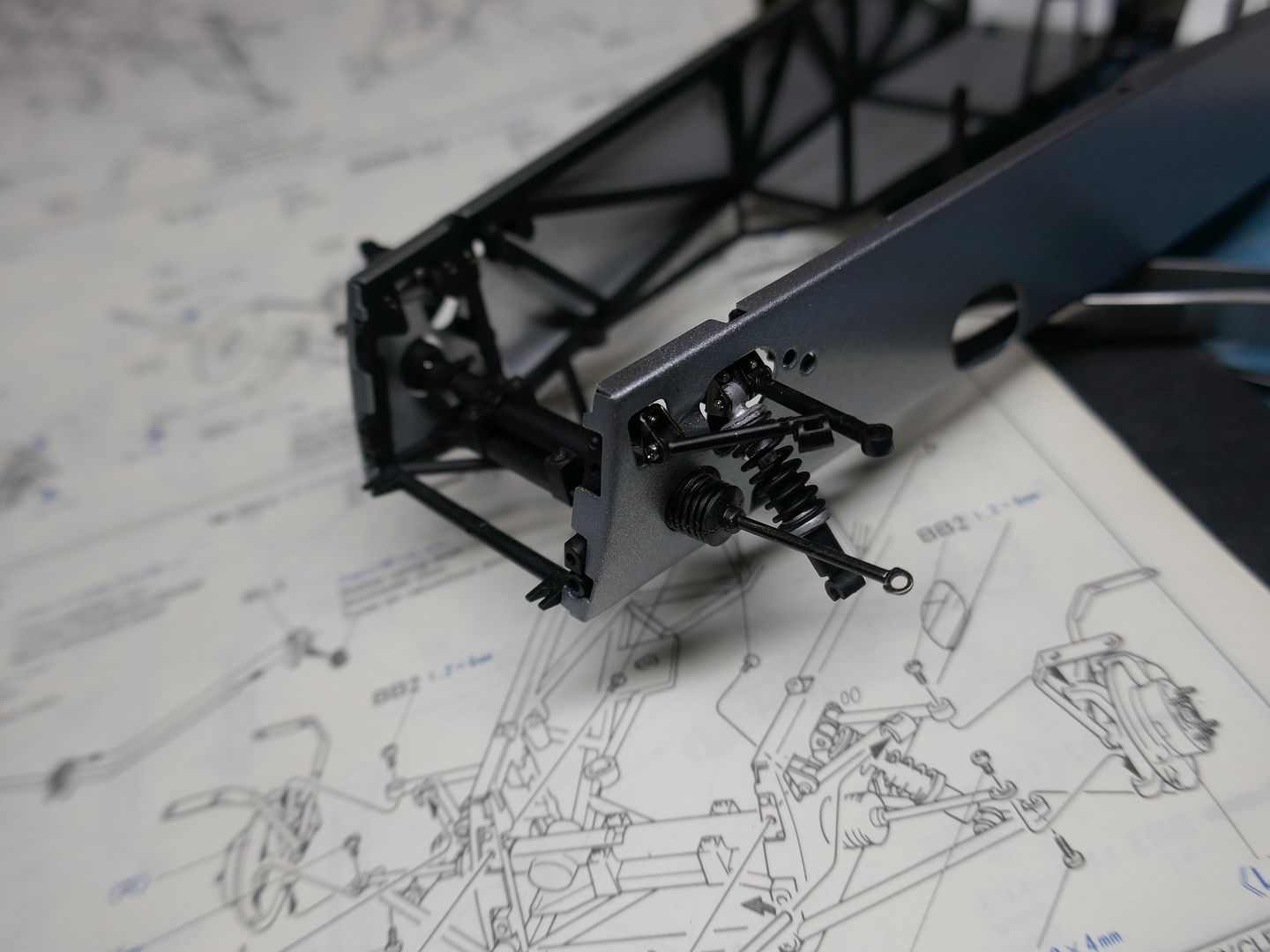
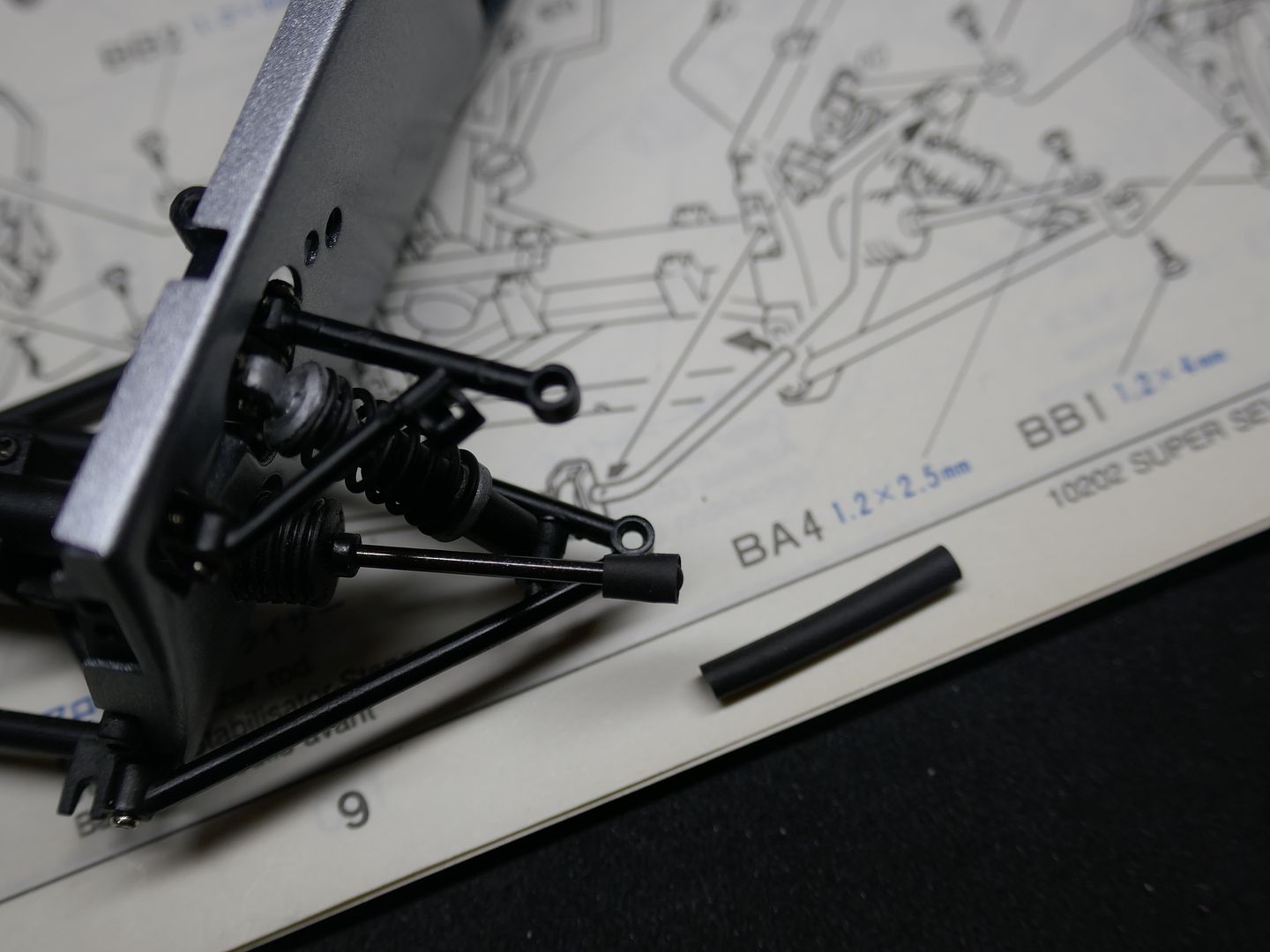
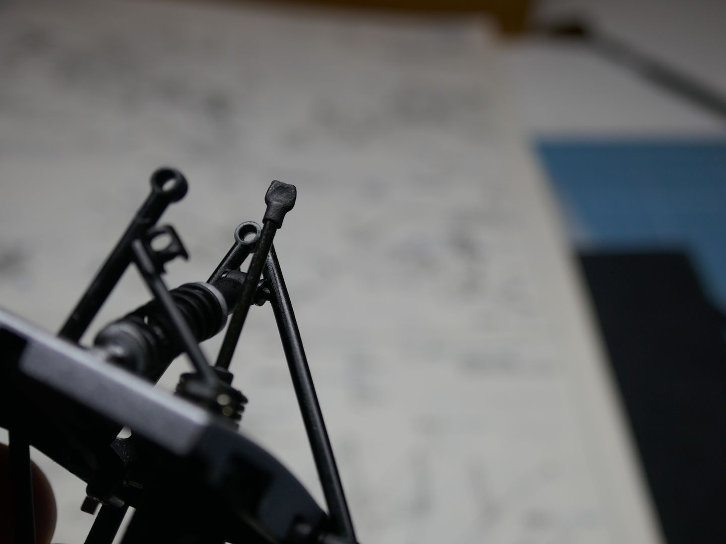
I added some heat shrink rubber tube on the end of the steering arms to represent the ball joints at the end
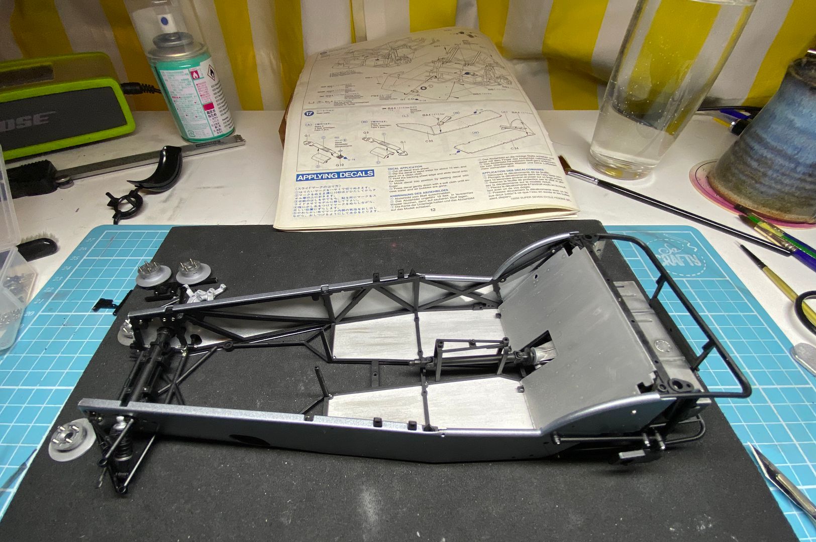
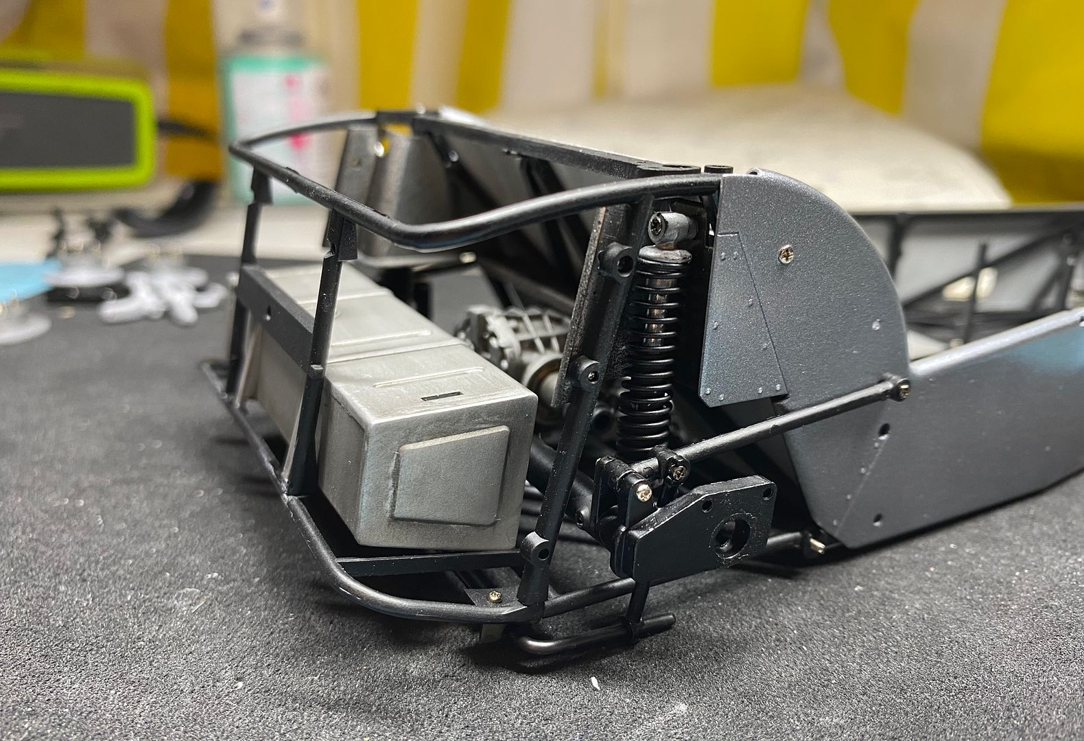
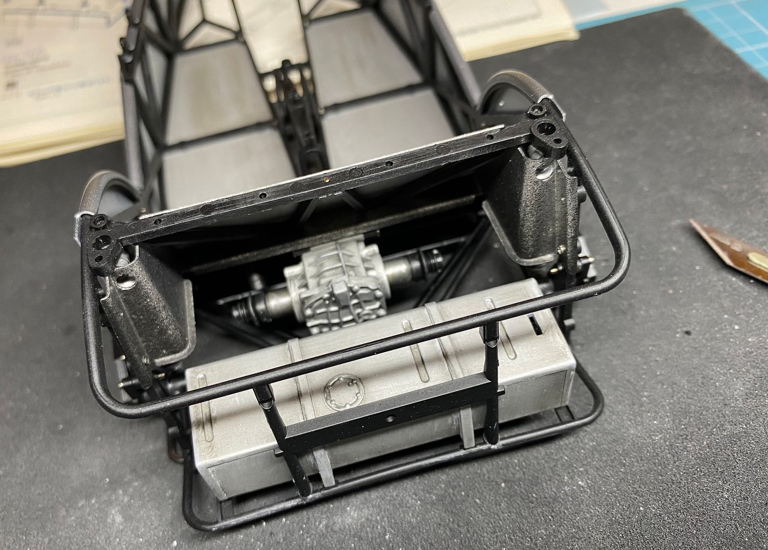
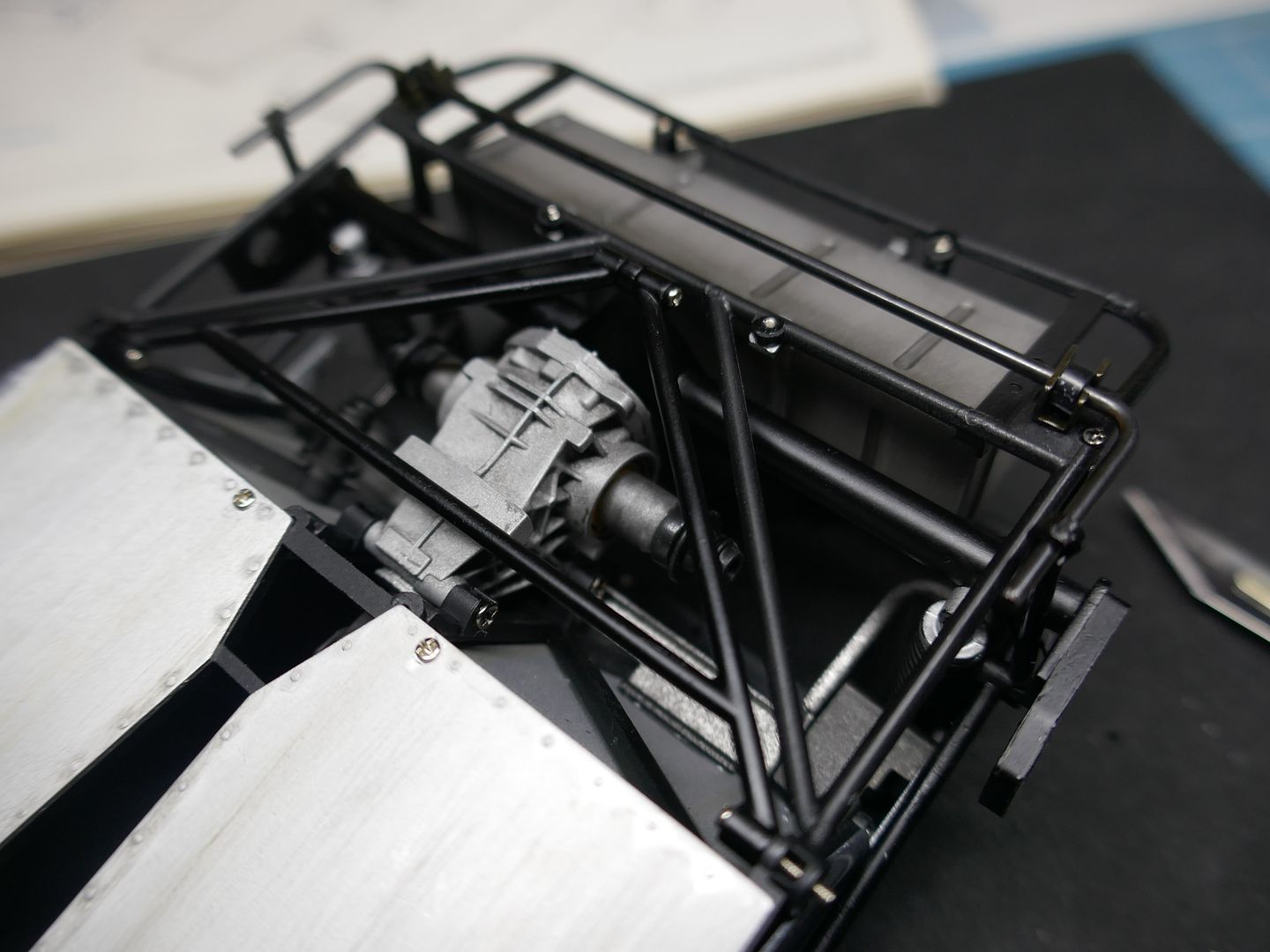
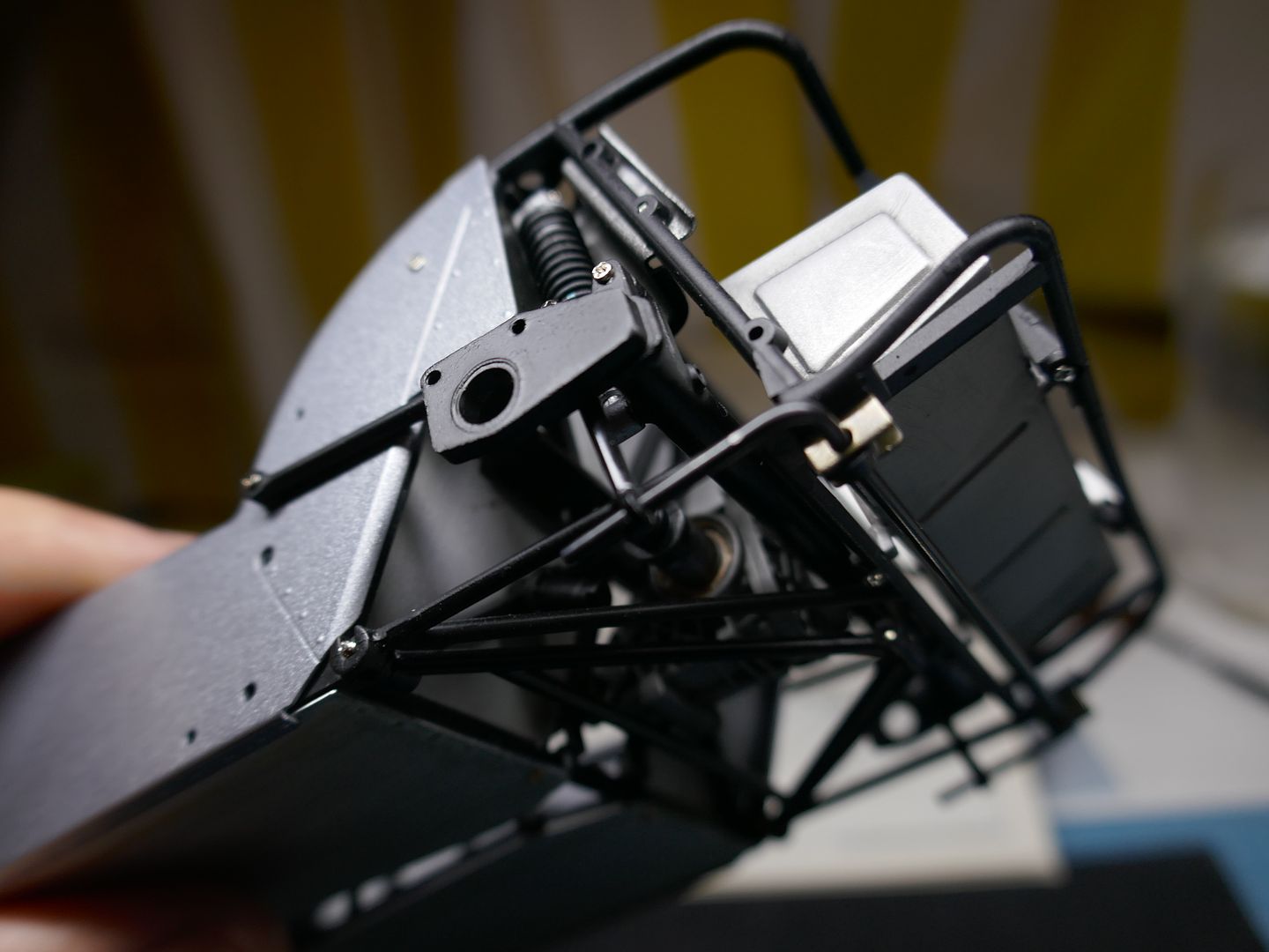
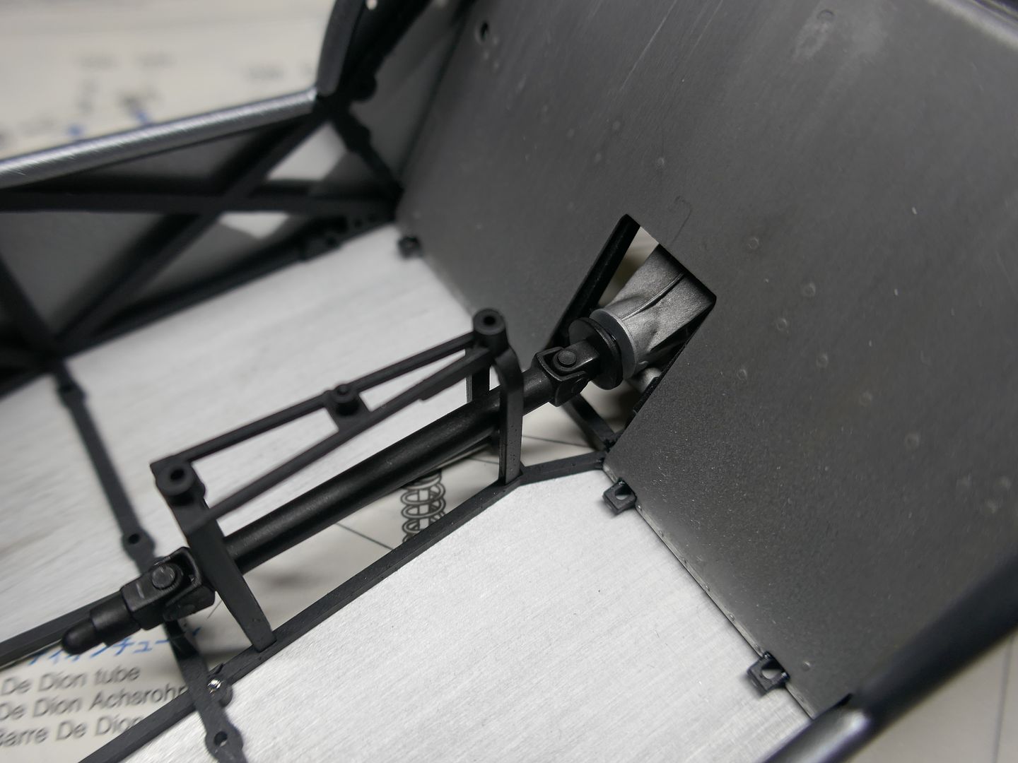
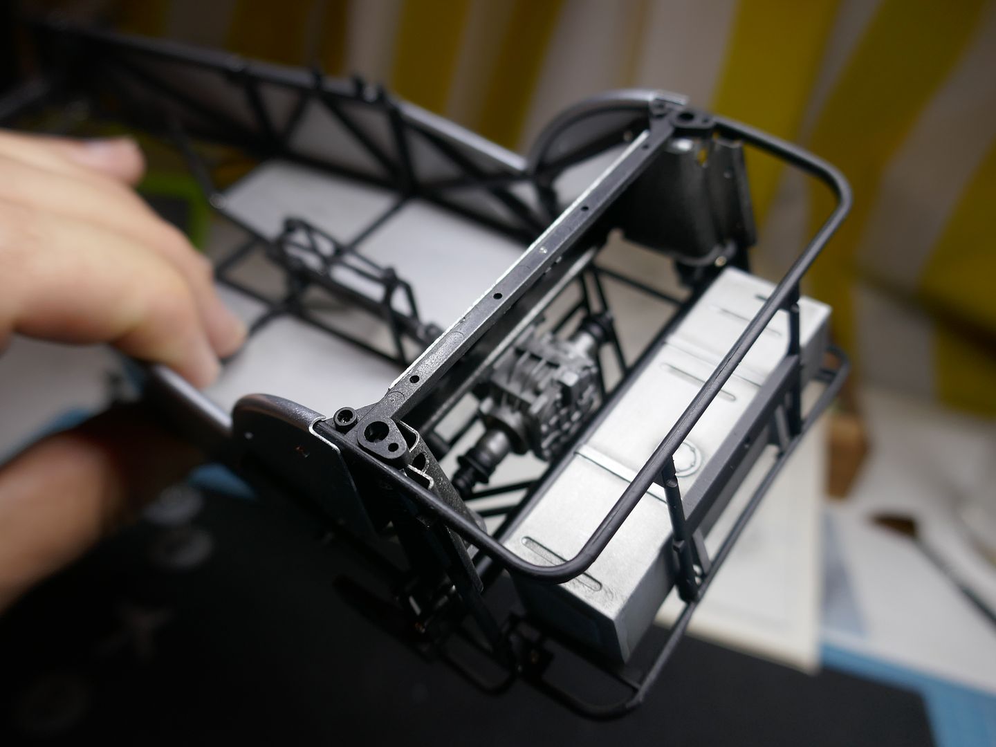
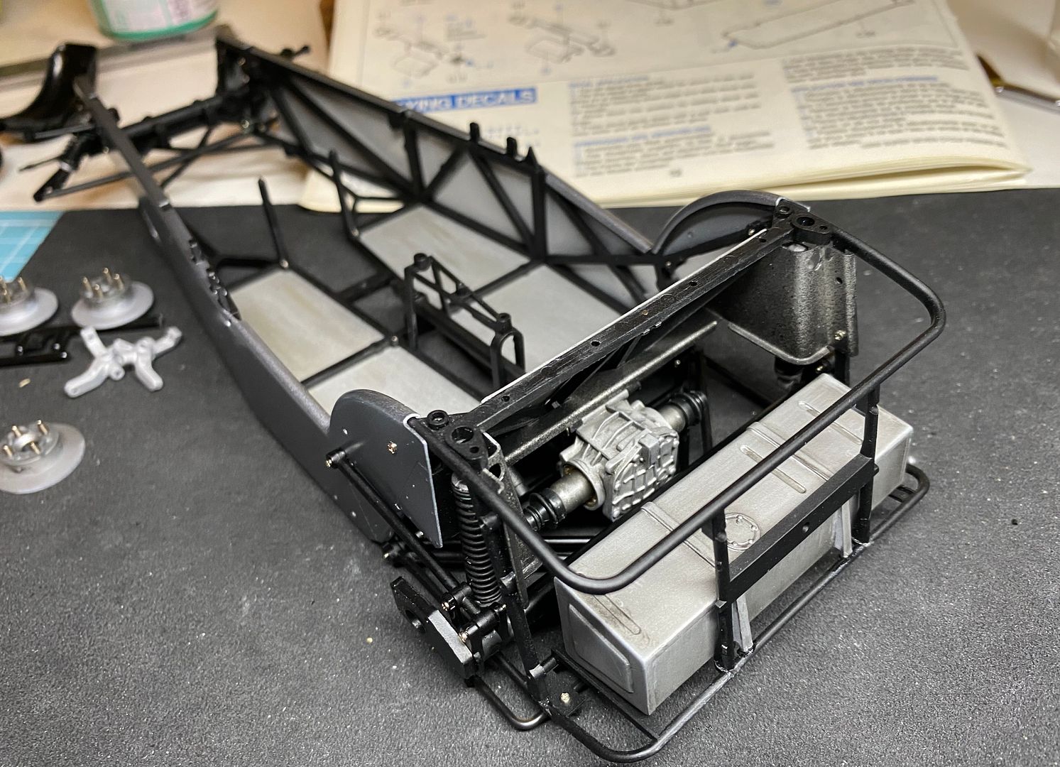
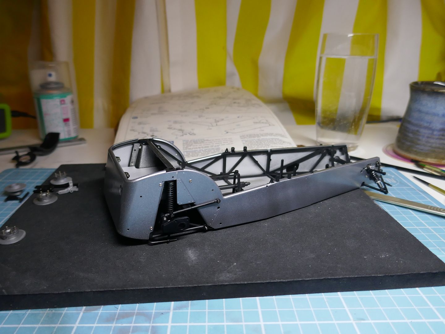
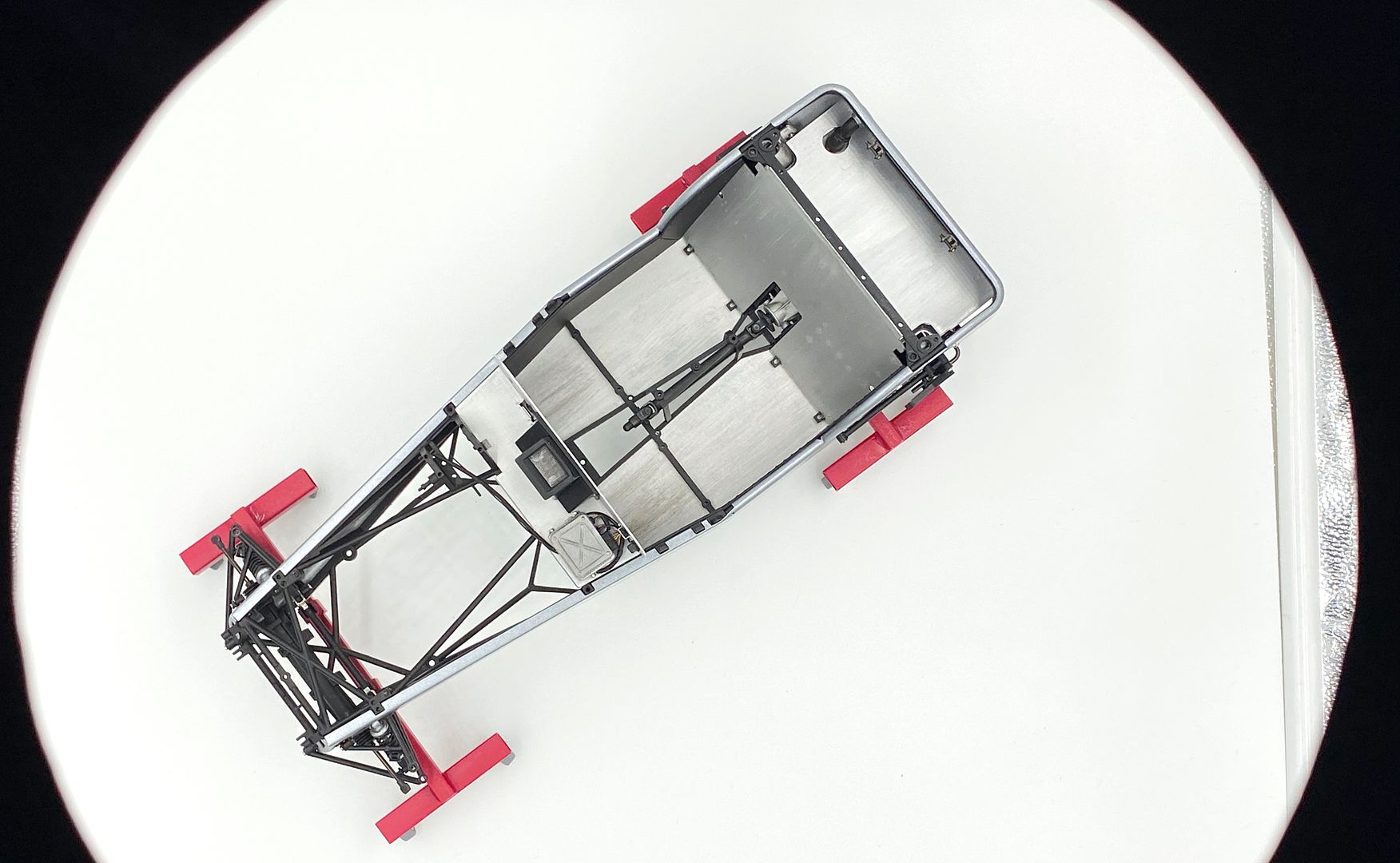
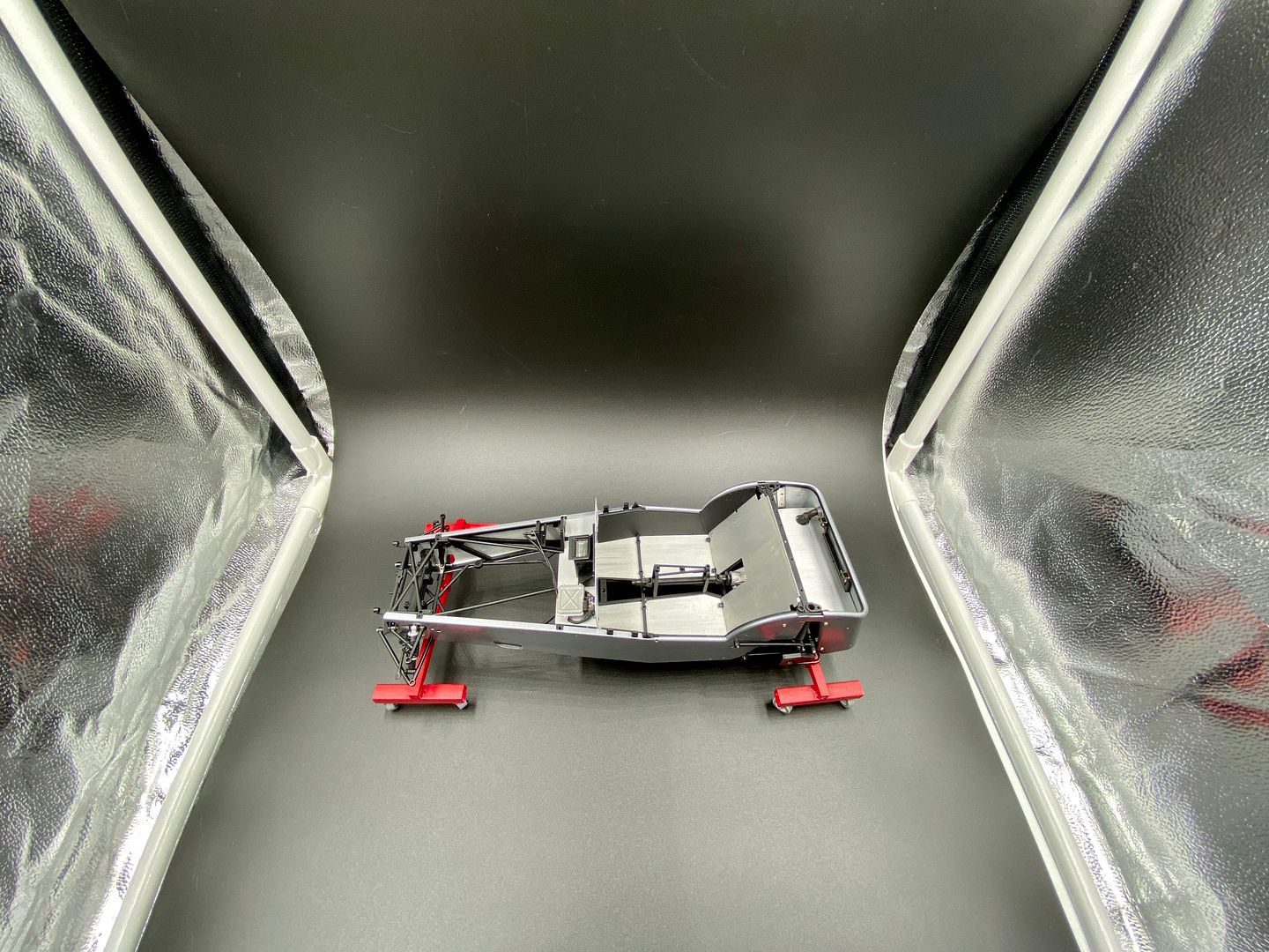
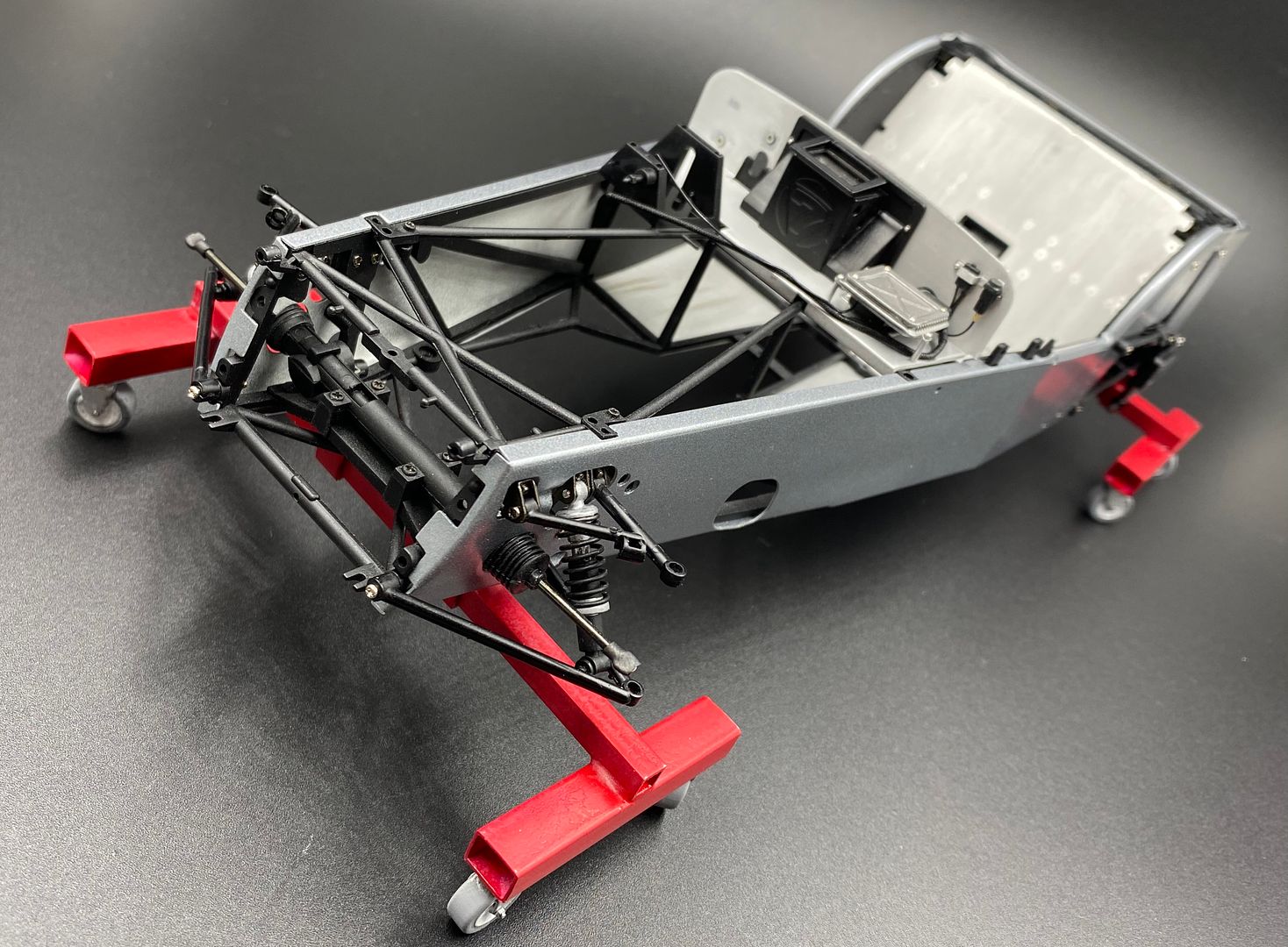
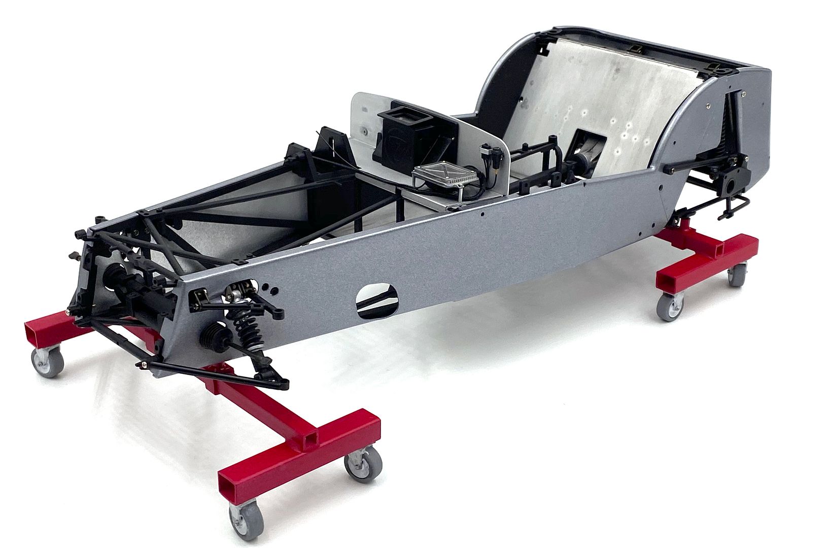
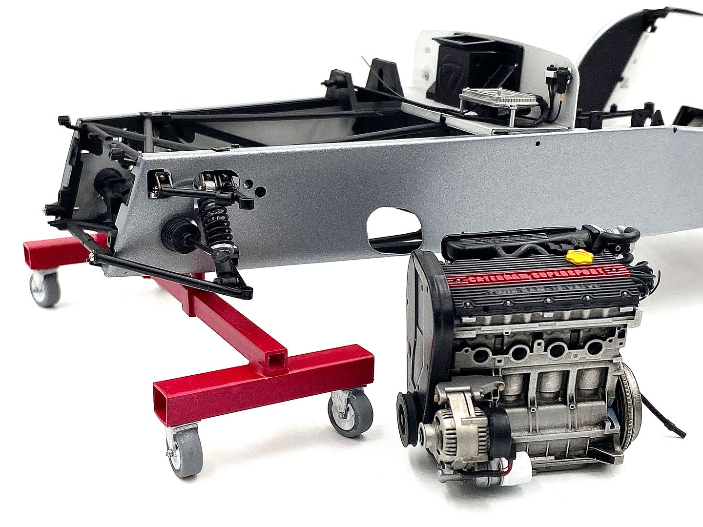
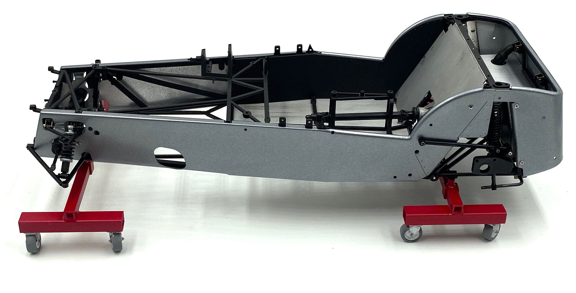
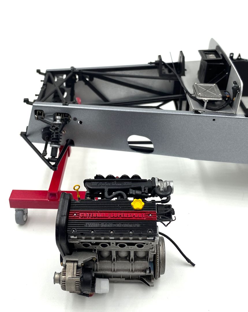


I fitted the suspension, front and rear. Nothing much to change on the kit at this point - it is pretty spot on - I tweak the wheel track slightly with the hubs at a later point. The layout and geometry is spot on, and you can actually change the 'set-up' and see the changes if you fiddle with the trailing arms and de-dion tube - I need to video it sometime in the future!
I also painted and fitted the diff and the fuel tank....


I added some heat shrink rubber tube on the end of the steering arms to represent the ball joints at the end


Gassing Station | Scale Models | Top of Page | What's New | My Stuff


