Yellow Ford Interior Lighting Relay
Discussion
Hi,
This is copy of my post on the TVR Griffith forum and I was hoping someone on the PH In-Car Electrics section could help me.
Looking to get my interior light working.
The above Yellow relay is missing which some say the light can still be swiitched on but mine doesn't.
Checked all the usual things so just got a relay and thought I would test it before trying it in place.
Got a early edition 85GG 13C718 AA.
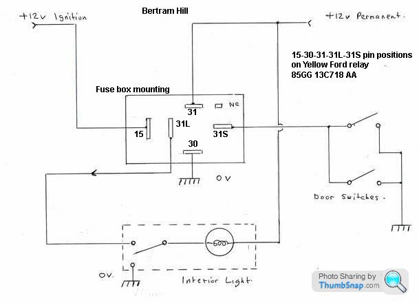
The interweb guides to testing a 5 pin relay I looked at didn't tie up with the pin numbers so I have borrowed Mr Hills drawing and added a few notes.

I have a battery and multimeter, so how should I test the relay?
Thanks.

This is copy of my post on the TVR Griffith forum and I was hoping someone on the PH In-Car Electrics section could help me.
Looking to get my interior light working.
The above Yellow relay is missing which some say the light can still be swiitched on but mine doesn't.
Checked all the usual things so just got a relay and thought I would test it before trying it in place.
Got a early edition 85GG 13C718 AA.
The interweb guides to testing a 5 pin relay I looked at didn't tie up with the pin numbers so I have borrowed Mr Hills drawing and added a few notes.

I have a battery and multimeter, so how should I test the relay?
Thanks.

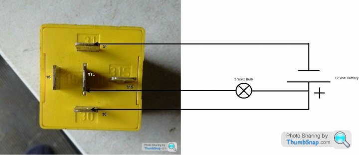
This was the bench test I did to prove the used relay I bought was working......

Penelope Stopit said:
Do you mean bench test it? If so

Once you've got as far as connecting it up as above diagram shows
Momentarily connect a negative from the battery to terminal 31 S of the relay (simulating the opening/closing of a door)
The 5 Watt bulb should remain illuminated for the pre-set time of the relay
Once the above has been proven to be ok
Momentarily connect a negative from the battery to terminal 31 S of the relay, the 5 Watt bulb has illuminated, now connect a positive from the battery to terminal 15 of the relay (simulating the ignition being switched on)
The 5 Watt bulb should be extinguished as soon as ignition on is simulated
It's best that you wire in a 3 or 5 amp in-line fuse to the battery positive for testing purposes (better be safe than sorry)
No Iggy Pop
All sorted now thanks.
Once you've got as far as connecting it up as above diagram shows
Momentarily connect a negative from the battery to terminal 31 S of the relay (simulating the opening/closing of a door)
The 5 Watt bulb should remain illuminated for the pre-set time of the relay
Once the above has been proven to be ok
Momentarily connect a negative from the battery to terminal 31 S of the relay, the 5 Watt bulb has illuminated, now connect a positive from the battery to terminal 15 of the relay (simulating the ignition being switched on)
The 5 Watt bulb should be extinguished as soon as ignition on is simulated
It's best that you wire in a 3 or 5 amp in-line fuse to the battery positive for testing purposes (better be safe than sorry)
No Iggy Pop

Gassing Station | In-Car Electronics | Top of Page | What's New | My Stuff


