MBE Cable alternative
Discussion
I gave myself a little challenge to learn a little bit more about RS232 and TTL communications with respect to the MBE ECU and diagnostic software.
Usually I use the standard type cable that I made up a few years ago from parts lying around in my bits box.
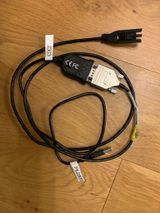
So that's the 3 pin connector to a serial 9-way connector and then use a PL2303 serial to USB converter. Fairly standard and described elsewhere on Pistonheads.
Instead I decided to make something a little less chunky. I came up with the following.
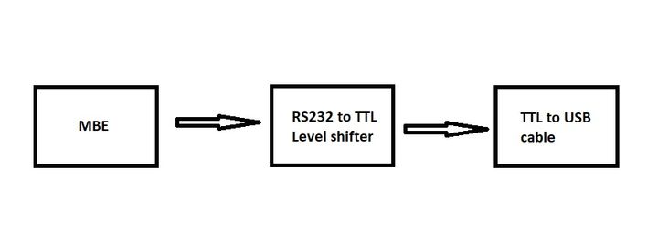
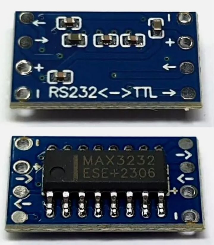
The level shifter converts the RS232 voltages and inverts to the standard TTL 5V signals.
The TTL to USB converter cable uses the CP2102 chip I believe.
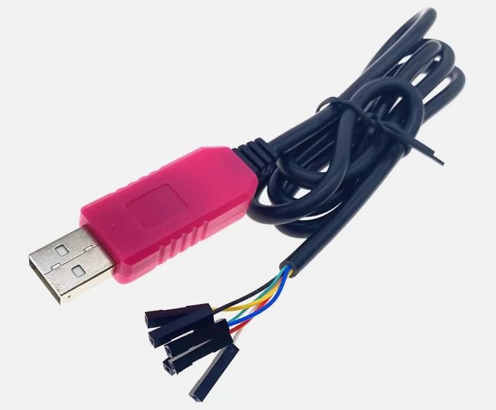
Red - 5V to power the level shifter
Black - Ground (-ve)
White - TXD - Goes to the input connection of the TTL of the level shifter
Green - RXD - Goes to the output connection of the TTL of the level shifter
Yellow and Blue not used.
On the RS232 side of the level shifter and the 3 pin connector
Pin 3 - Ground - Goes to the -ve connection point of the level shifter
Pin 2 - TX - Goes to the input connection of the RS232 side of the level shifter
Pin 1 - RX - Goes to the output connection of the RS232 side of the level shifter
See the following test cable I made up and I checked it worked using the AJP diagnostics software on an Android phone. Hence the extra USB to micro USB cable.
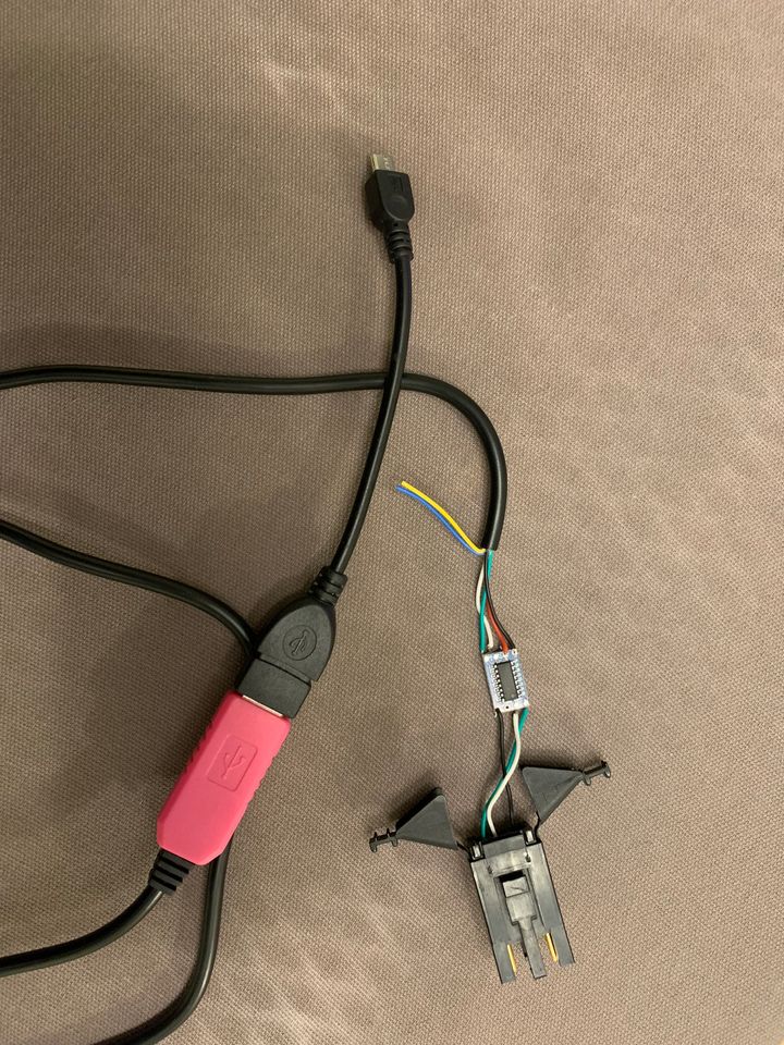
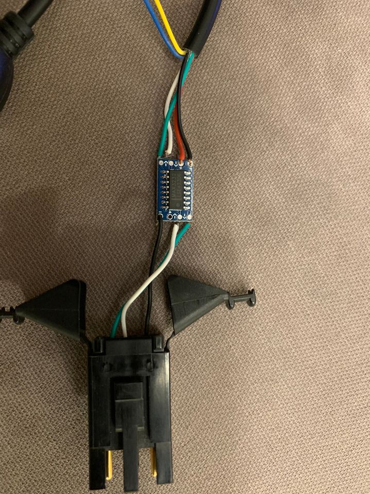
A tidy up and some heatshrink would make this a nice alternative MBE cable. Cost of the level board £2 and the USB converter cable £8 from eBay. I'm sure you can get these cheaper elsewhere if you looked.
Hope this info is useful.
Usually I use the standard type cable that I made up a few years ago from parts lying around in my bits box.
So that's the 3 pin connector to a serial 9-way connector and then use a PL2303 serial to USB converter. Fairly standard and described elsewhere on Pistonheads.
Instead I decided to make something a little less chunky. I came up with the following.
The level shifter converts the RS232 voltages and inverts to the standard TTL 5V signals.
The TTL to USB converter cable uses the CP2102 chip I believe.
Red - 5V to power the level shifter
Black - Ground (-ve)
White - TXD - Goes to the input connection of the TTL of the level shifter
Green - RXD - Goes to the output connection of the TTL of the level shifter
Yellow and Blue not used.
On the RS232 side of the level shifter and the 3 pin connector
Pin 3 - Ground - Goes to the -ve connection point of the level shifter
Pin 2 - TX - Goes to the input connection of the RS232 side of the level shifter
Pin 1 - RX - Goes to the output connection of the RS232 side of the level shifter
See the following test cable I made up and I checked it worked using the AJP diagnostics software on an Android phone. Hence the extra USB to micro USB cable.
A tidy up and some heatshrink would make this a nice alternative MBE cable. Cost of the level board £2 and the USB converter cable £8 from eBay. I'm sure you can get these cheaper elsewhere if you looked.
Hope this info is useful.
Many USB to Serial connectors are often sketchy comms wise avoid Prolific chipsets and use FTDI that use to be the thing with Megasquirt ECU's now the chipset is onboard in the latter ECU's , FTDI was rock solid whilst I used one , you dont want comms issues whilst loading firmware etc on any ECU  I also made my own for this reason and used a donor case
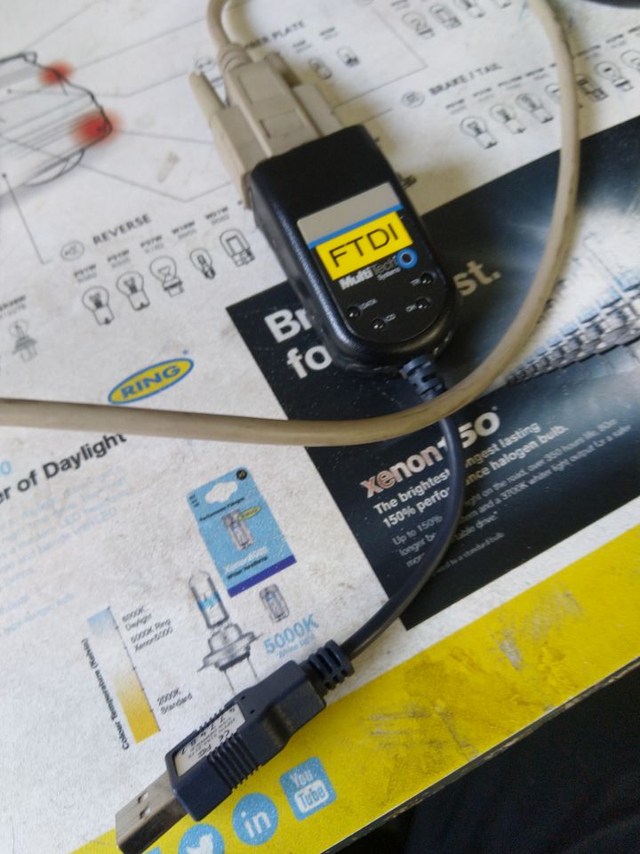
 I also made my own for this reason and used a donor case
 Gassing Station | General TVR Stuff & Gossip | Top of Page | What's New | My Stuff


