Temp Sensor / Rad Fan Switch Identification
Discussion


Rad fans not coming on.
Installed jumper across secondary contacts at Fan Relay socket. Fans came on.
Tested relay on bench. All good.
Removed left headlight pod to look at otter switch. No otter switch?!
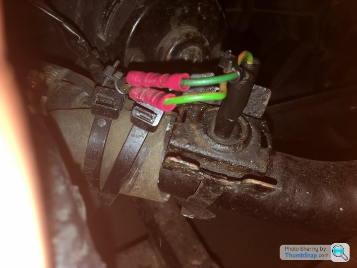
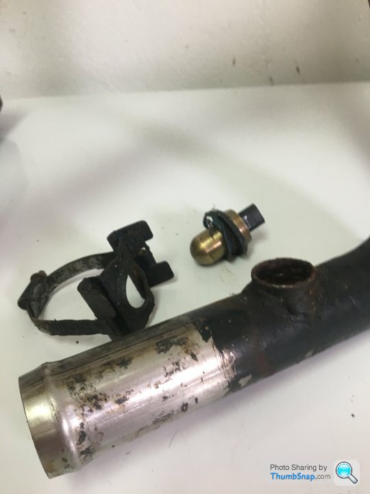
Closer look in engine bay. Aftermarket switch installed in rad hose. It’s actually a hardline, is this standard?
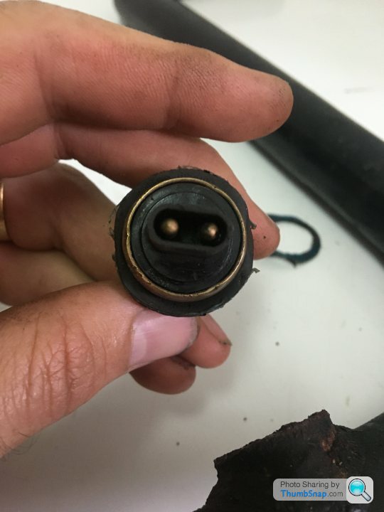
I pulled the contacts and shorted them together. Fans came on.
Cleaned corrosion from jack and plug contacts. Let engine warm up, reached 100+ and fans failed to come on.
Now I’m left with this mystery... Can anyone ID this switch? Or a Mfg?
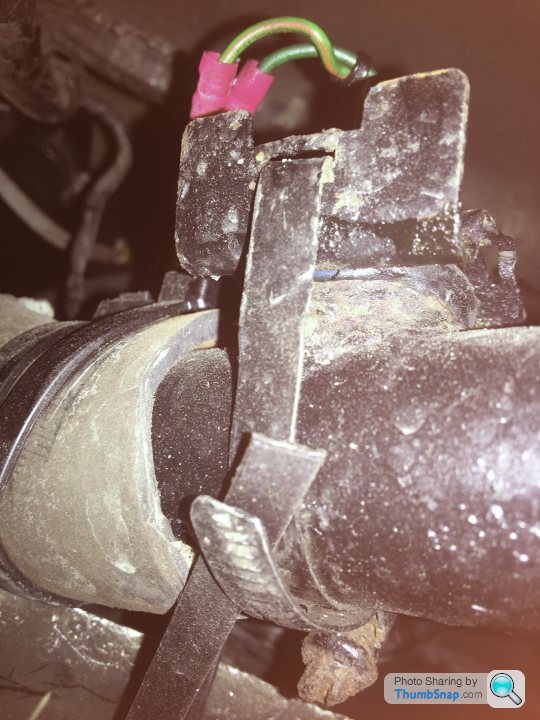
Tomorrow I’ll loosen the band clamp to see if I can just peel that bracket off and unthread the sensor and order a standard replacement. Suggested closing temp ~90 C?
I guess this is a good opportunity to drain and flush the coolant.
Installed jumper across secondary contacts at Fan Relay socket. Fans came on.
Tested relay on bench. All good.
Removed left headlight pod to look at otter switch. No otter switch?!
Closer look in engine bay. Aftermarket switch installed in rad hose. It’s actually a hardline, is this standard?
I pulled the contacts and shorted them together. Fans came on.
Cleaned corrosion from jack and plug contacts. Let engine warm up, reached 100+ and fans failed to come on.
Now I’m left with this mystery... Can anyone ID this switch? Or a Mfg?
Tomorrow I’ll loosen the band clamp to see if I can just peel that bracket off and unthread the sensor and order a standard replacement. Suggested closing temp ~90 C?
I guess this is a good opportunity to drain and flush the coolant.
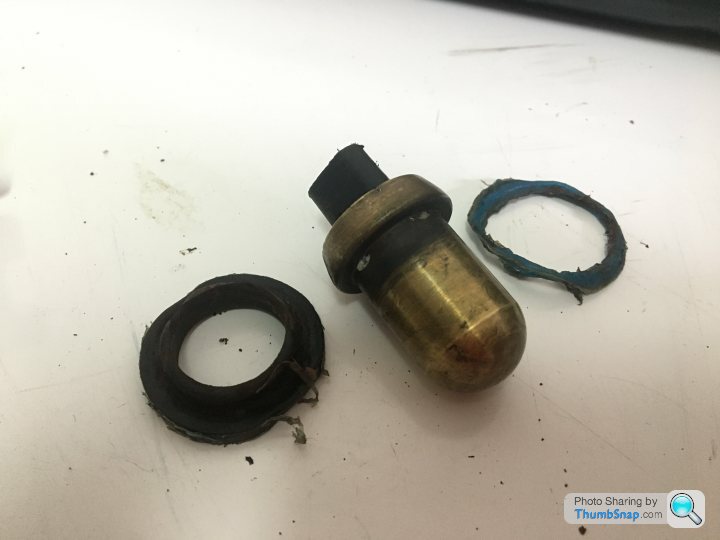
Pulled the switch out today. Was easier to remove the entire hardline and disassemble out of the engine bay.
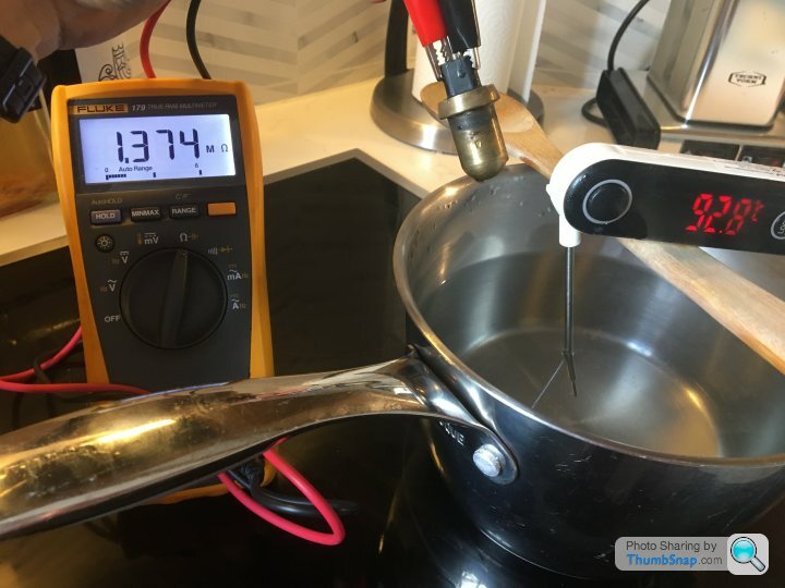
Cleaned the switch and tested in a pot of hot water.
At room temp, resistance was approx 1.3MOhms. Not wide open (50M is the standard in my industry) but definitely not passing enough current to energize the relay solenoid.
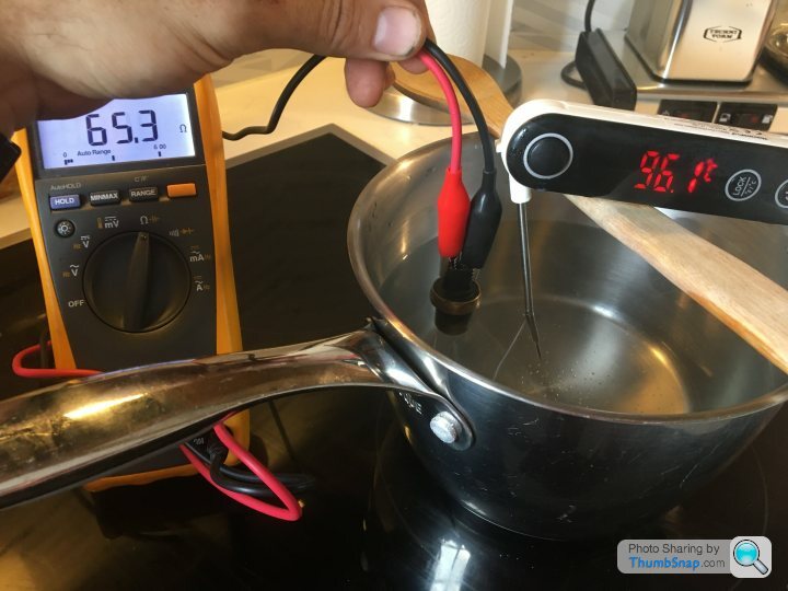
At about 90C, resistance began to drop. Read 65Ohms at about 30s. Reached minimum of 25Ohms or so after about 2 minutes above 90C. This should be plenty low enough to actuate the solenoid.
I may reinstall everything and give it another shot.
In the meantime, has any ever seen a switch similar to this? No markings other than a warning on the gasket not to reuse. I’m going to take that as more of a suggestion than a rule.
Cleaned the switch and tested in a pot of hot water.
At room temp, resistance was approx 1.3MOhms. Not wide open (50M is the standard in my industry) but definitely not passing enough current to energize the relay solenoid.
At about 90C, resistance began to drop. Read 65Ohms at about 30s. Reached minimum of 25Ohms or so after about 2 minutes above 90C. This should be plenty low enough to actuate the solenoid.
I may reinstall everything and give it another shot.
In the meantime, has any ever seen a switch similar to this? No markings other than a warning on the gasket not to reuse. I’m going to take that as more of a suggestion than a rule.
The Otter switches have contacts built into the top of them that make at a certain temperature, the way to test Otter switches is by heating them up and measuring for continuity, there should be very little resistance across the contacts
Anyway, you've ordered a new one and should be good to go soon
Anyway, you've ordered a new one and should be good to go soon

Phillpot,
That’s a fine method of getting a rough idea of whether a switch is working. But an incandescent bulb can glow or it can GLOW. How much glow do we need to energize our relay?
The voltage supplied by the battery (via temp switch) to the fan relay will be reduced before reaching the relay by (Vs*(R1/(R1+R2))) where R1 is the resistance across the switch and R2 is the resistance across the solenoid. If this remaining voltage is less than the amount required to energize and latch the relay, the fan will not come on.
From past experience I expect this relay will energize at approx 6-7VDC. I expect the solenoid should have a operating resistance in the region of 50-100 Ohms, we can call it 75. If we assume zero loss through the fuse box, Vs=12VDC.
Using the prior eqn, (12VDC*(65Ohms/(65Ohms+75Ohms))= 6.43VDC. So, we are right on the border of energizing that relay. Any lower, it should work. Any higher, no love.
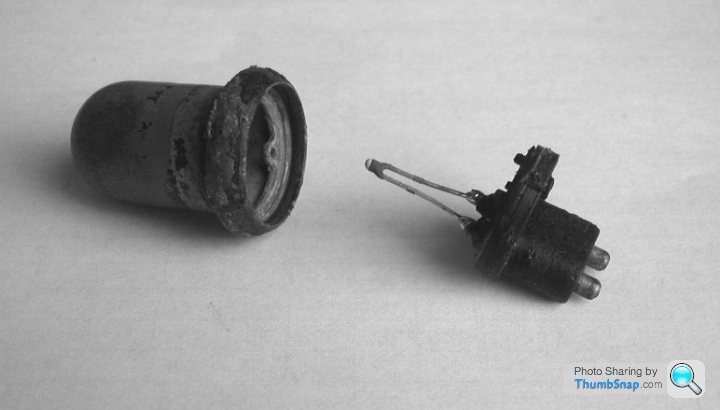
It can be helpful to note the difference between the originally installed Otter bimetal switch and this Lucas temp switch. In truth, the Lucas switch would more accurately be described as an NTC (Negative Temperature Coefficient) thermistor. The Otter unit works similar to a circuit breaker by relying on the dissimilar expansion rates of metals at similar temperatures. The bonded bimetal strip will curve when heated. At a calibrated temperature the curve metal strip will touch a second contact, complete the circuit and “switch” on. The Lucas unit does not provide a discrete “on/off” signal like a true switch. They do not definitively “switch” at a set temperature. They decrease resistance across a defined range as temperature increases.
VS
That’s a fine method of getting a rough idea of whether a switch is working. But an incandescent bulb can glow or it can GLOW. How much glow do we need to energize our relay?
The voltage supplied by the battery (via temp switch) to the fan relay will be reduced before reaching the relay by (Vs*(R1/(R1+R2))) where R1 is the resistance across the switch and R2 is the resistance across the solenoid. If this remaining voltage is less than the amount required to energize and latch the relay, the fan will not come on.
From past experience I expect this relay will energize at approx 6-7VDC. I expect the solenoid should have a operating resistance in the region of 50-100 Ohms, we can call it 75. If we assume zero loss through the fuse box, Vs=12VDC.
Using the prior eqn, (12VDC*(65Ohms/(65Ohms+75Ohms))= 6.43VDC. So, we are right on the border of energizing that relay. Any lower, it should work. Any higher, no love.
It can be helpful to note the difference between the originally installed Otter bimetal switch and this Lucas temp switch. In truth, the Lucas switch would more accurately be described as an NTC (Negative Temperature Coefficient) thermistor. The Otter unit works similar to a circuit breaker by relying on the dissimilar expansion rates of metals at similar temperatures. The bonded bimetal strip will curve when heated. At a calibrated temperature the curve metal strip will touch a second contact, complete the circuit and “switch” on. The Lucas unit does not provide a discrete “on/off” signal like a true switch. They do not definitively “switch” at a set temperature. They decrease resistance across a defined range as temperature increases.
VS
Edited by VyperSpace on Friday 9th September 23:11

Otter Switch Laid Bare - https://forums.jag-lovers.com/t/otter-switch-laid-...
Found here - http://lotus-europa.com/index.html
Edited by Polly Grigora on Saturday 10th September 07:56
VyperSpace said:
That’s a fine method of getting a rough idea of whether a switch is working. . . . . . and lots of very technical stuff!
Plan 2: Why not just rig it up with a battery (9volt PP3 to allow for cruddy old wiring and corroded connections), a relay and a bulb, drop in boiling water and see if bulb lights up? 
phillpot said:
Plan 2: Why not just rig it up with a battery (9volt PP3 to allow for cruddy old wiring and corroded connections), a relay and a bulb, drop in boiling water and see if bulb lights up?
Now you’re getting somewhere. Please post results.I’ll stick with Kirchhoff’s method and a DMM.
Polly, great pics showing showing the difference between a switch and a thermistor. Thanks for posting.
VyperSpace said:
phillpot said:
Plan 2: Why not just rig it up with a battery (9volt PP3 to allow for cruddy old wiring and corroded connections), a relay and a bulb, drop in boiling water and see if bulb lights up?
Now you’re getting somewhere. Please post results.I’ll stick with Kirchhoff’s method and a DMM.
Polly, great pics showing showing the difference between a switch and a thermistor. Thanks for posting.
Please forgive me for waffling on about otter switch testing, have come across your type of temperature sensor in the past but can't remember where, it was only after reading the following that I realised what you were dealing with
VyperSpace said:
It can be helpful to note the difference between the originally installed Otter bimetal switch and this Lucas temp switch. In truth, the Lucas switch would more accurately be described as an NTC (Negative Temperature Coefficient) thermistor. The Otter unit works similar to a circuit breaker by relying on the dissimilar expansion rates of metals at similar temperatures. The bonded bimetal strip will curve when heated. At a calibrated temperature the curve metal strip will touch a second contact, complete the circuit and “switch” on. The Lucas unit does not provide a discrete “on/off” signal like a true switch. They do not definitively “switch” at a set temperature. They decrease resistance across a defined range as temperature increases.
Knowing that when the charging voltage is up to a possible 14.5 volts that the relay pull-in voltage will be reached sooner than when the battery voltage is a little above 12 volts excites me, sorry but I'm funny that waySomething I have noticed is that many websites do list the Lucas SNB712 as a switch or Otter switch, frightening really
Anyway, your findings and calculations are very interesting and will no doubt help others understand the circuits operation better
Gassing Station | Wedges | Top of Page | What's New | My Stuff