S1 body-off lift
Discussion


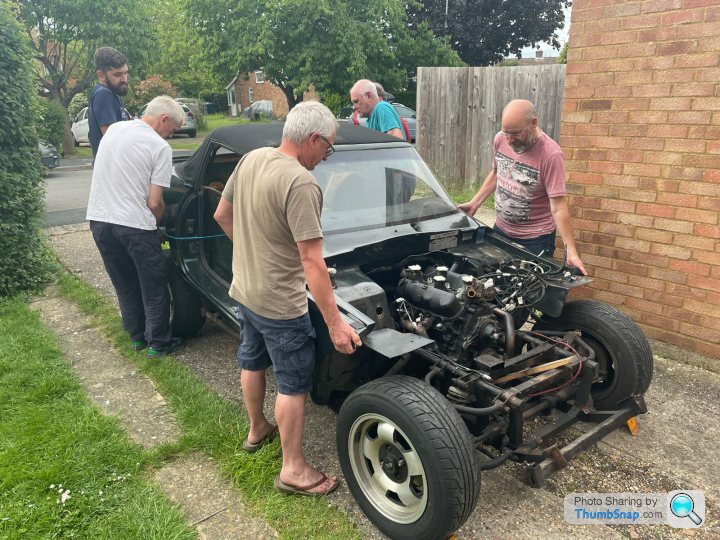
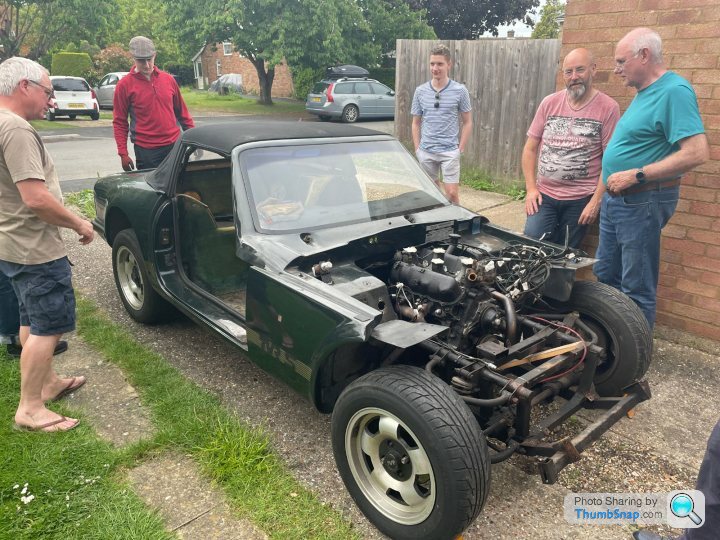
The big step of dismantling for restoration finally happened yesterday evening. The body is off the chassis. I took the approach of inviting a bunch of fellow car club members round and we did it in 10 minutes.
To give credit, I had searched this forum and come up with (1) a checklist of things to disconnect first and (2) the technique for the lift. That all worked perfectly so a big thank you to all who have posted your experiences on here. In the same spirit I'll add a series of pictures to this thread and (if I can figure out how) a video showing the final lift.
To give credit, I had searched this forum and come up with (1) a checklist of things to disconnect first and (2) the technique for the lift. That all worked perfectly so a big thank you to all who have posted your experiences on here. In the same spirit I'll add a series of pictures to this thread and (if I can figure out how) a video showing the final lift.
The starting point was that I'd already removed the bonnet, boot and doors, nearly all the interior, and engine bay ancillaries such as radiator, fuel injection unit, plenum chamber, brake servo and clutch master cylinder. It should be possible to leave quite a few of these attached but I was going to remove them anyway so it made sense to get them out of the way first.
The wiring loom remains attached to the body, except for the battery to starter motor cable. The fuel system up to the filter/metering unit and the hydraulic pipes for brakes and clutch remain attached to the chassis. So all the connections across that body/chassis divide need to be detached. Most are fairly obvious under the bonnet but the hidden or less obvious ones are:
- reverse light switch, connector is accessible through the holes in tunnel when console has been removed.
- rubber gaiter around gearstick, not just the leather trim gaiter on the console
- fuel pump wiring, connector is under left rear wheel arch or nearby bits of chassis
- fuel level sender, remove wires from terminals on end of tank under left rear wheel arch
- fuel filler needs both lower and upper hoses freeing by loosening the jubilee clips. I then cut through the lower one with a Stanley knife, after which I could wriggle the pipe free from the upper hose. Then I sealed the open neck of the tank with plastic tied on with wire, to avoid filling the garage with petrol vapour.
Other people have referred to sealant around the fuel filler and an earth strap there, but these weren't on my car. It's an early 1988 build so maybe they were added later.
And then there are the interior items: body bolts in the corners of the seat/footwells (also two in the boot floor), seat belts, and the handbrake. Two of the body bolts at the rear outside corners face backwards, the rest face downwards.
With the brakes disconnected wheel chocks were used to keep the car, and later the chassis, in place. The steering was last to be disconnected as I needed that to position the car with space either side on the drive. I'd undone the upper UJ previously to ensure it was freed off and then reconnected it with the bolts not fully tightened so it was quick release.
The video linked below shows the final separation. At the point where it starts we'd already lifted the back and slid a 3x3 timber beam between the top of the chassis rails and bottom of the rear shelf. This made subsequent lifting much easier and supported the body more evenly. The rope was to stop it sliding backwards when the body was at a steeper angle. The back is heavier than the front hence more people there.
The boot area can flex up and down rather a lot once it is off the chassis support. The roof is up to minimise upwards flexing during the lift, but after putting the body down there was about a 10mm gap at the front of the Targa panels due to the boot sagging. I've put some wood blocks underneath to support the boot whilst it's "parked".
https://youtu.be/VjSe9avyrQ4
Retrotune said:
Hi Simon
I have recently purchased an S1 that needs chassis work outriggers are vanishing.
Just wondered how you were getting on and if you have any updates or photos of work
Hopefully will be lifting the body of in the next few weeks
I am based stone staffs
Regards j
Hello JI have recently purchased an S1 that needs chassis work outriggers are vanishing.
Just wondered how you were getting on and if you have any updates or photos of work
Hopefully will be lifting the body of in the next few weeks
I am based stone staffs
Regards j
Glad you found it helpful. It is quiet on here as Mike says, but I find it a far more useful repository of information than Facebook, which always seems very transient to me.
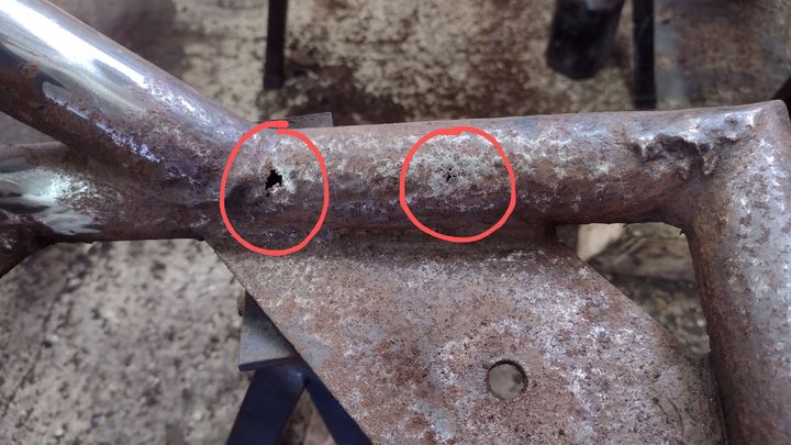
The work on my S1 has progressed slowly, entirely due to me, since the body lift. I took everything off the chassis and initially thought it was OK and wouldn't need much doing. However when I stripped the muck, waxoyl and powder coating off it wasn't so good. The n/s outrigger had been replaced quite a few years ago with the body still on and that was fine, but the o/s outrigger and both body mounting brackets (in front of rear wheels) had rusted through in places. That's beyond my very limited welding ability so I've had it professionally repaired and recoated.
That work was just finished on Thursday and I should get it back in the next week I hope. And then the even bigger job begins - putting it all back together again! I'll post some before & after photos of the chassis when I've got it back.
Simon
Magpies' post reminded me I'd not put the photos here of the repaired chassis. Here are the 'before and after' shots.
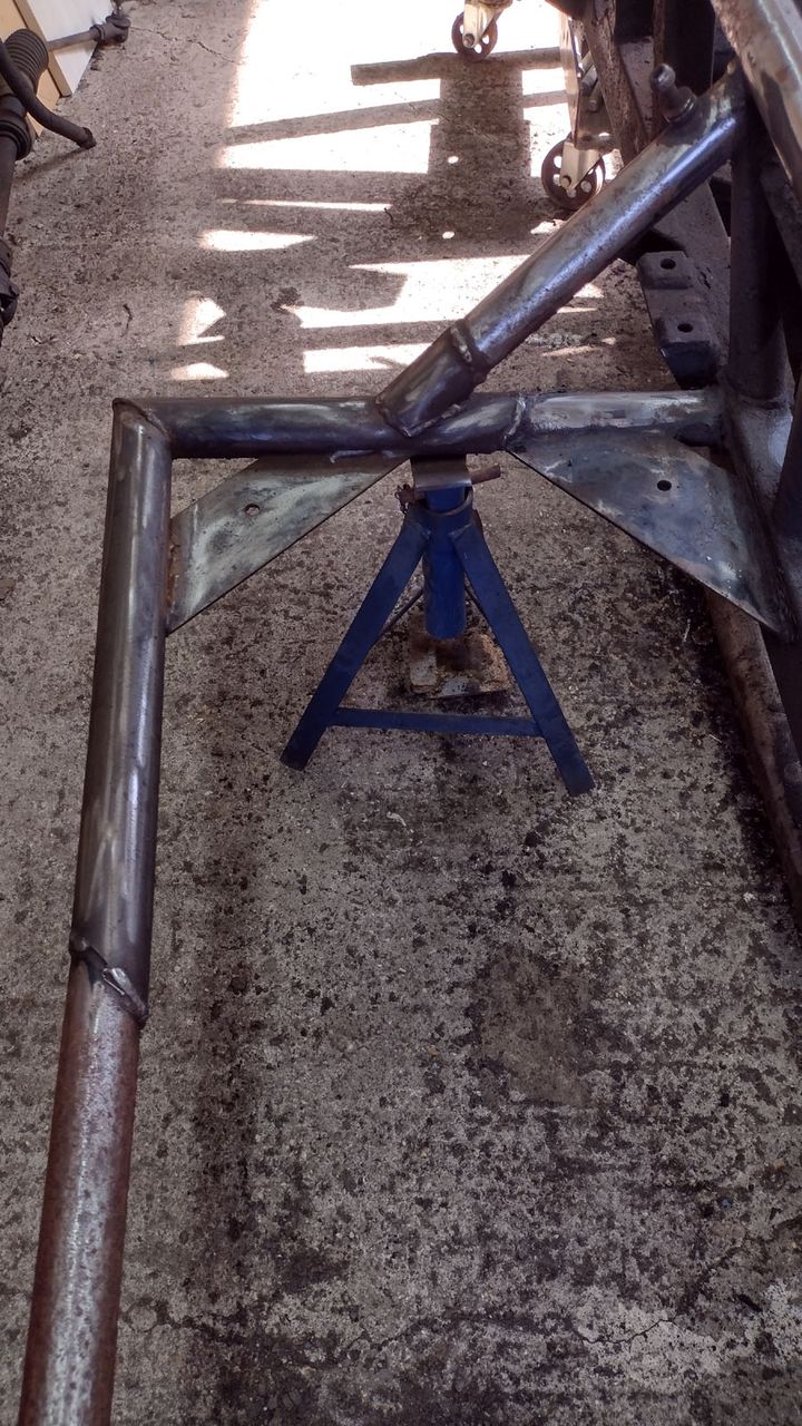
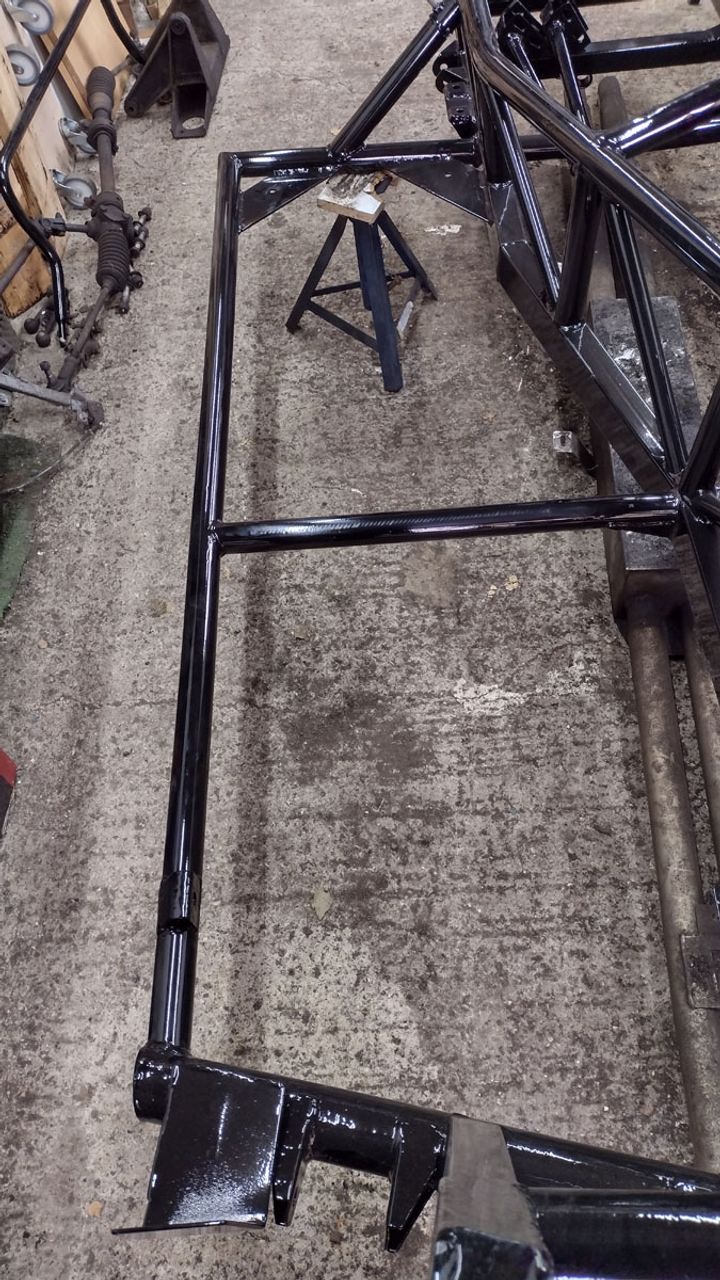
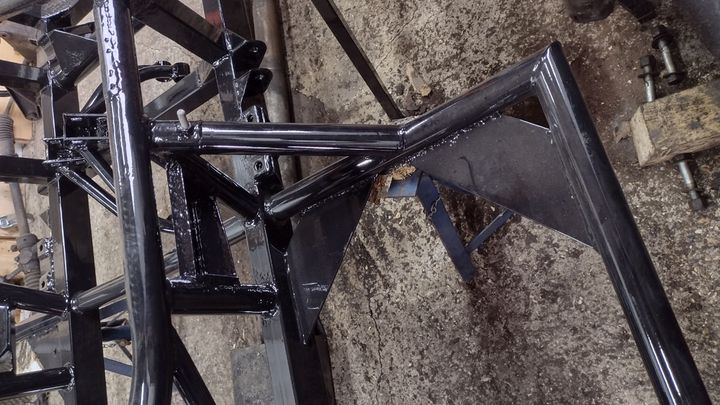
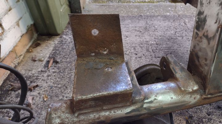
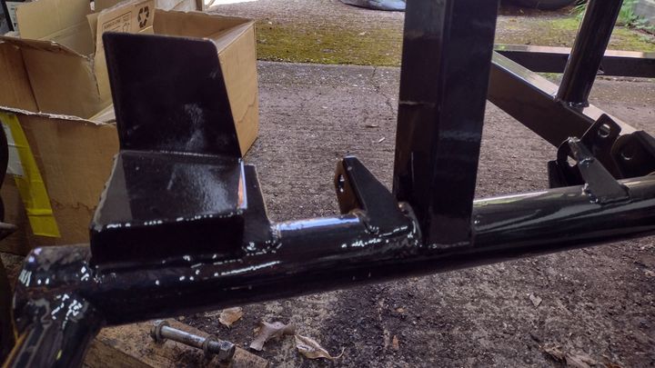
Credit where it's due, the work was done by Mat Smith in Downham Market (https://www.matsmithsportscars.com/)
I have done a little more since then, I've fitted new poly bushes to all the wishbones. I tried to fit one to the chassis but was having real problems getting the first bolt lined up. The threaded part went in fine but when the shank reached the tube inside the bush it would not go any further despite some persuasion from a club hammer. The bolt goes through the tube with no problem when it's on the bench so I must have something misaligned. Any tips?
An update on fitting the wishbones - I got the two n/s ones fitted but am now stuck with a different problem on the o/s.
Firstly one fix I worked out was to redrill the mounting holes. The new powder coating had very slightly reduced their diameter and with everything here being a tight fit that was enough to make the bolts difficult or impossible to get into the mountings. Drilling it back to the metal again means the fit is just right.
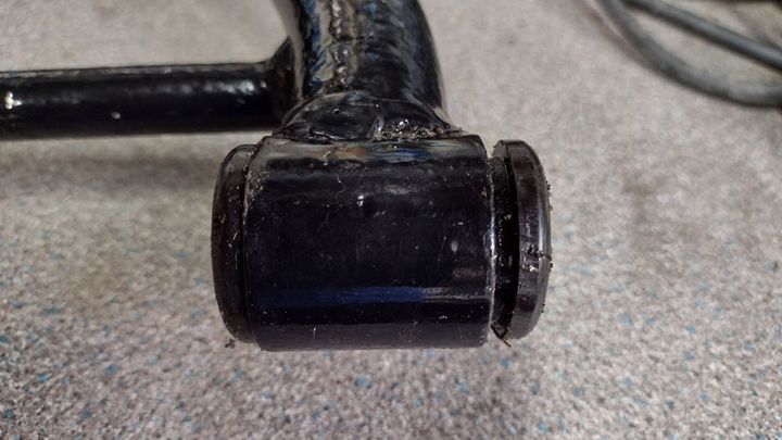
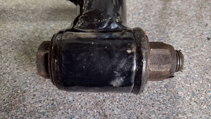
The problem I have now involves the new bushes not seating quite right in the wishbones. The photos show the problem. The bushes come as two 'top hat' shaped halves and a steel tube for the centre. One half mounts just right but the other stops about 2mm out - photo on left. The tube is flush with the surface of the properly fitting half and recessed inside the half that is not fully in.
If I attach one of the bolts and wind it in then it compresses the bush so that the 2mm gap disappears but the bush also bulges outwards - photo on right. As soon as I remove the bolt it opens the gap again.
Trying to fit this to the chassis mounts will compress the bush but the tube on the side where it's flush gets stuck and digs into the powder coat instead of centralising across the width of the bush. I can't remove the bush from the wishbone as it's an interference fit - I used an engineer's vice to get it in and various pliers, vice grips and even a chain wrench can't get enough grip to remove it.
Suggestions for how to get them into the mounting flanges?
Firstly one fix I worked out was to redrill the mounting holes. The new powder coating had very slightly reduced their diameter and with everything here being a tight fit that was enough to make the bolts difficult or impossible to get into the mountings. Drilling it back to the metal again means the fit is just right.
The problem I have now involves the new bushes not seating quite right in the wishbones. The photos show the problem. The bushes come as two 'top hat' shaped halves and a steel tube for the centre. One half mounts just right but the other stops about 2mm out - photo on left. The tube is flush with the surface of the properly fitting half and recessed inside the half that is not fully in.
If I attach one of the bolts and wind it in then it compresses the bush so that the 2mm gap disappears but the bush also bulges outwards - photo on right. As soon as I remove the bolt it opens the gap again.
Trying to fit this to the chassis mounts will compress the bush but the tube on the side where it's flush gets stuck and digs into the powder coat instead of centralising across the width of the bush. I can't remove the bush from the wishbone as it's an interference fit - I used an engineer's vice to get it in and various pliers, vice grips and even a chain wrench can't get enough grip to remove it.
Suggestions for how to get them into the mounting flanges?
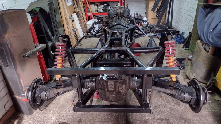
Reviving this thread after nearly a year. I rather ran out of enthusiasm for several months but have been pressing on with the rebuild recently. This weekend I reached a mini-milestone - the drivetrain, suspension and steering rack are all now back in the chassis.  A few bolts are missing or need replacing but it's pretty much there. Fuel system and brakes are next.
I fixed the problem in my last post about the front wishbones. The problem in the end was that the powder coating on the refurbished chassis was just thick enough to make the metal tubes in the bushes an interference fit. Stripping the powder coat off the inside of the mounting flanges with a flap wheel in an electric drill was enough to let the bushes move into place.
A couple of other tips: If both gearbox and diff are fitted then there's not enough room to fit the propshaft! Gearbox, then propshaft, then diff.
Having had a nightmare extracting the Torx-head halfshaft bolts, I replaced them with conventional hex heads. They will fit, just, but do it with the CV joints at an angle and rotate the shaft so it's angled away from the bolt you want to fit. This means keep rotating the shaft 60deg between each bolt. There's not enough room for a ring spanner or socket but an open ended spanner is fine.
A few bolts are missing or need replacing but it's pretty much there. Fuel system and brakes are next.I fixed the problem in my last post about the front wishbones. The problem in the end was that the powder coating on the refurbished chassis was just thick enough to make the metal tubes in the bushes an interference fit. Stripping the powder coat off the inside of the mounting flanges with a flap wheel in an electric drill was enough to let the bushes move into place.
A couple of other tips: If both gearbox and diff are fitted then there's not enough room to fit the propshaft!
Gearbox, then propshaft, then diff. Having had a nightmare extracting the Torx-head halfshaft bolts, I replaced them with conventional hex heads. They will fit, just, but do it with the CV joints at an angle and rotate the shaft so it's angled away from the bolt you want to fit. This means keep rotating the shaft 60deg between each bolt. There's not enough room for a ring spanner or socket but an open ended spanner is fine.
phillpot said:
Propshaft will go in/come out if you just drop the front mounting bolts on the "diff" and lower the nose a bit 
Thanks Mike, yes that what I figured out. I slackened the two rear bolts on the rear mount and removed the front two plus the ones holding the cradle onto the front mounts. Then I could drop the front end so that the cradle crossmember sat on the lower chassis rails. It was annoying to have to undo all the bolts I'd just done up, but at least I didn't have to redo the 3D puzzle of how to get the diff+cradle into or out of the chassis.magpies said:
Will you be able to achieve the torque required for the cv joint bolts using an open end spanner? It may be worth drilling the bolt heads to accept locking wire to ensure they do not self undo.
That's an interesting thought about drilling and lockwiring the bolts.I did try tightening another bolt to the driveshaft bolt settings, using a torque wrench but holding it at a length equal to the spanner length, and feeling how much pull I needed. That was about as much force as I could sensibly apply single-handed. I tightened the driveshaft bolts up to as near as possible the same force using the spanner. I know it's not exact but I believe it's close enough for starters and I'm going to periodically check them for tightness once it's back on the road.
Gassing Station | S Series | Top of Page | What's New | My Stuff