WIDE OPEN BONNET, A DIFFERENT APPROACH!
Discussion


Apologies for the delay, I know a few people were interested, hope it is not too late.
The following sounds more complicated than it is. The method is really simple, if a bit tricky to get the initial dimensions sorted out. The crucial bit was finding where the optimum pivot position should be. I did the geometry and came out with moving the pivot 59mm forward and dropping it 10-12mm. And a couple of mm makes a surprising difference!
Aims 1. To at least double the angle of opening of the bonnet for access while maintaining at least 1" clearance when open
2. Not to need to cut the bonnet
3. Easy removal of bonnet (car was soon to be sprayed and also due and engine out overhaul)
4. Remove the bending load, and spread the load, on the ply. These have failed on a few cars
5 To include a simple restraint to stop the bonnet over opening too far by accident, and a means of restraining the bonnet at the catch end to provide security when open especially in a wind.
6. Generally to have a engineering designed solution, not a fabricators afterthought! But there had to be no fancy items I couldn't make myself!
I did NOT seek to keep the original mounting slot. That was an unnecessary design restraint as I had no intention of reverting to original. Furthermore the original mounting tube is too thin and frequently distorted. So my design works from the front chassis cross tube. On the later cars that is not a continuous straight tube but that is not an issue with this design. What I do not know however is if the cross tube is the same internal size, clearance on 34mm. If not part of the design would need amendment to fit.
A key point in my design are sliding tubes inserted either side inside the chassis tube which allow sideways movement. When set right these are through bolted in place. I was surprised to find the positions of the ply were so far out it needed about 25mm adjustment across the car. Now we get to the only manufacturing problem.
The steel chassis tube is 1 1/2" (38.1mm) external and under 2mm thick wall which gives 34.4mm internal. There is no tube available to slide in with a good fit. 2 pieces 150mm long are needed, 34mm x 34mm ideally. 1 1/2 used to be common and sure enough my local fabricator had a few bits of thick wall tube that could be milled down to 34 x 34 Alternatives might be 40x40x5mm box and get 3mm milled off all sides, .40x40x2mm angle cut down and welded. 30 x30 x2mm box with pads welded on.
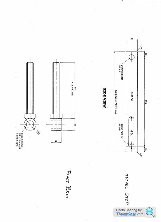
The sliding tubes have a 3mm plate welded on the end to which a piece of 12mm ID steel tube is welded as per diagram.
In order to satisfy 4 above the pivot needed to be in axial line with the ply, that constrained the position of the pivot to being behind the ply. Luckily that didnt turn out to be an issue. The optimum pivot point just cleared the ply.
I started with the details from 4 cars, ground clearance under front of bonnet, position of front and bottom of bonnet relative to front of chassis and the height of the existing pivot above ground level.. Those four were NOT a full range of S chassis/bonnet alternatives but what I have seen since suggests it is transferable to other cars. The original height of pivot was pretty consistent in the 245-250mm range. The crucial dimensions of the bonnet were also remarkably consistent including on a V8 bonnet.
I plotted the position of the original pivot and the bonnet lower front on the drawing board and then worked out optional pivot positions and tested them. (Trained on the drawing board..pre CAD days!) When I had my optimum, just to be sure I did the old fashioned cardboard cut out and tested it!
The optimum position moves the pivot forwards 59mm and lowers it 12mm. I was able to use the original pivot bolt, M12 with 12mm ID tube welded on end. This brought the external diameter of the tube just clear of the ply at the optimum position , which is lucky! The original pivot bolt is effectively now reversed and provides the forward and backwards adjustment. I did experiment with a nice stainless rose joint but the OD of the rose joint was too large and moved the pivot too far from the optimum, and the shank of the rose joint restricted forward and backwards adjustment too much.
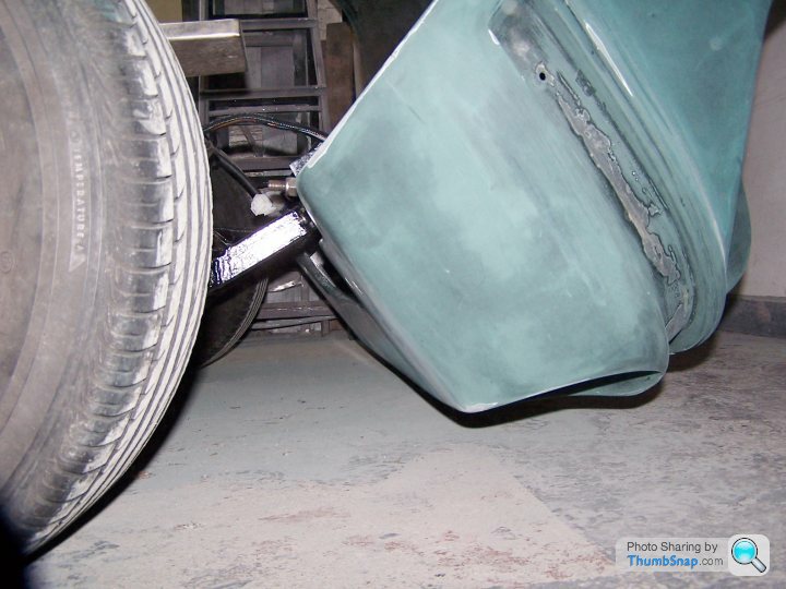
The original opening is little more than 30 degrees. This solution gives 70 degrees. It is NOT fully vertical, now does it need to be. I can get the radiator out with the bonnet up. The 1" ground clearance is achieved when up so OK to use on flat ground or grass without damage.
The bonnet clears without being cut.
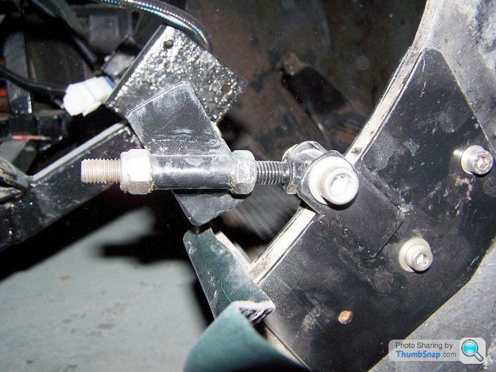
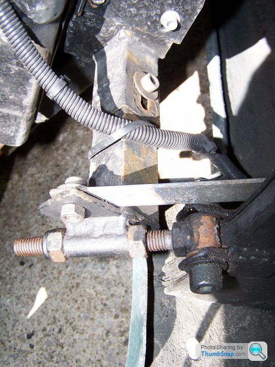
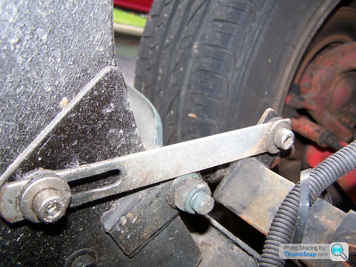
The bonnet now pivots of two 12mm stainless socket head screws with lock nuts, very easy to see and understand. To remove: Remove nuts, put wood and foam rubber under front of bonnet, disconnect the two (new) x pin electrical sockets. Close bonnet, remove M8 bolt from restraint, and slide out the pivot screws which are now easy to access.. Bonnet remains in place but can now readily be lifted away.
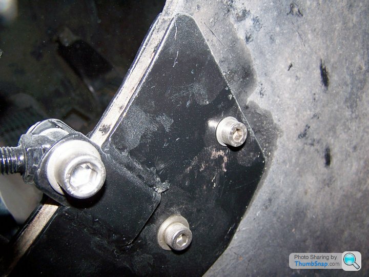
The plates holding the hinge to the bonnet ply were made considerably bigger to spread the load over a much greater area. If you think about the load on the ply at the mountings the original mounting bolts are not well positioned.The plates are extended by welded on sections to project behind the ply and those sections are drilled to provide the holes for the pivot screw. Note, the ply is 12mm think. I used 3mm plate which gave me a pivot width of 18mm. I made a mock up and found I needed to have greater clearance with washers to ease movement, so I welded the side sections on with spacers a touch thicker than the washers.
The plates are held on with 3 x M6 socket head bolts but the holes in the ply are 10mm that provides enough movement for vertical adjustment.
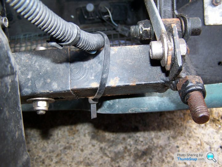
The limit stop was dead easy. 175mm of 20 x 5mm bar. Drilled and mounted to the chassis extension at one end and slotted at the other and fitted to one of the bolts holding the plates to the ply. A little bit of careful work and the slot comes to an end when the bonnet is 1" up AND the bar rests on the pivot bolt, that provides a very firm travel stop.
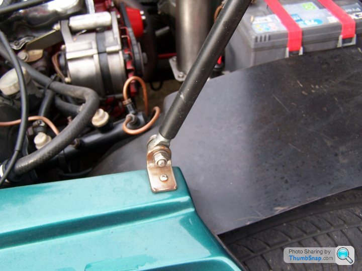
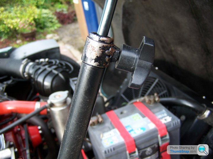
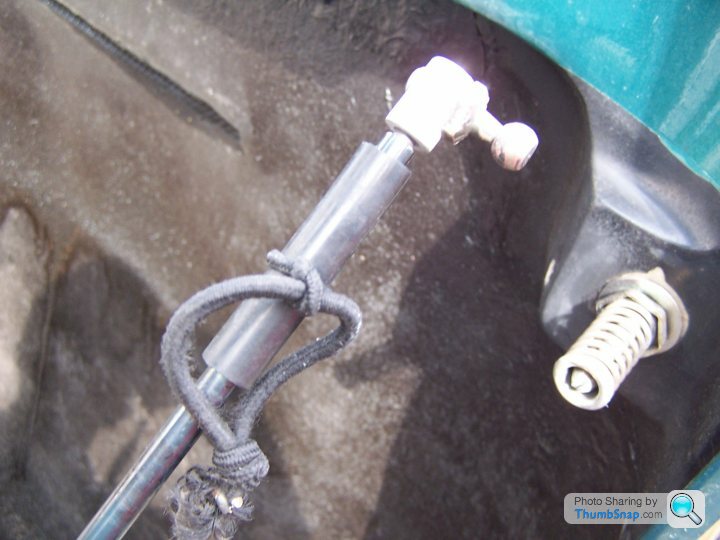
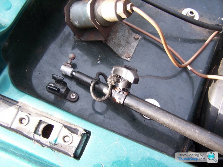
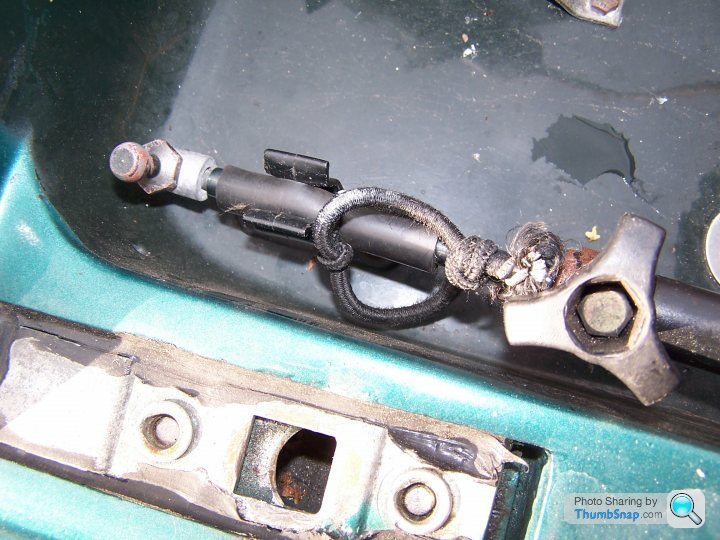
I then used a gas strut from a tailgate and its two ball end connectors. Pin drilled to let the gas out, welded an M5 nut on the side of the end of the cylinder and made up an M5 clamp screw so I now have an infinitely adjustable stay to support the bonnet.
I attach drawings of most parts and some photos of it in use.
I have no doubt that still leaves questions in your mind, so please ask.
The following sounds more complicated than it is. The method is really simple, if a bit tricky to get the initial dimensions sorted out. The crucial bit was finding where the optimum pivot position should be. I did the geometry and came out with moving the pivot 59mm forward and dropping it 10-12mm. And a couple of mm makes a surprising difference!
Aims 1. To at least double the angle of opening of the bonnet for access while maintaining at least 1" clearance when open
2. Not to need to cut the bonnet
3. Easy removal of bonnet (car was soon to be sprayed and also due and engine out overhaul)
4. Remove the bending load, and spread the load, on the ply. These have failed on a few cars
5 To include a simple restraint to stop the bonnet over opening too far by accident, and a means of restraining the bonnet at the catch end to provide security when open especially in a wind.
6. Generally to have a engineering designed solution, not a fabricators afterthought! But there had to be no fancy items I couldn't make myself!
I did NOT seek to keep the original mounting slot. That was an unnecessary design restraint as I had no intention of reverting to original. Furthermore the original mounting tube is too thin and frequently distorted. So my design works from the front chassis cross tube. On the later cars that is not a continuous straight tube but that is not an issue with this design. What I do not know however is if the cross tube is the same internal size, clearance on 34mm. If not part of the design would need amendment to fit.
A key point in my design are sliding tubes inserted either side inside the chassis tube which allow sideways movement. When set right these are through bolted in place. I was surprised to find the positions of the ply were so far out it needed about 25mm adjustment across the car. Now we get to the only manufacturing problem.
The steel chassis tube is 1 1/2" (38.1mm) external and under 2mm thick wall which gives 34.4mm internal. There is no tube available to slide in with a good fit. 2 pieces 150mm long are needed, 34mm x 34mm ideally. 1 1/2 used to be common and sure enough my local fabricator had a few bits of thick wall tube that could be milled down to 34 x 34 Alternatives might be 40x40x5mm box and get 3mm milled off all sides, .40x40x2mm angle cut down and welded. 30 x30 x2mm box with pads welded on.
The sliding tubes have a 3mm plate welded on the end to which a piece of 12mm ID steel tube is welded as per diagram.
In order to satisfy 4 above the pivot needed to be in axial line with the ply, that constrained the position of the pivot to being behind the ply. Luckily that didnt turn out to be an issue. The optimum pivot point just cleared the ply.
I started with the details from 4 cars, ground clearance under front of bonnet, position of front and bottom of bonnet relative to front of chassis and the height of the existing pivot above ground level.. Those four were NOT a full range of S chassis/bonnet alternatives but what I have seen since suggests it is transferable to other cars. The original height of pivot was pretty consistent in the 245-250mm range. The crucial dimensions of the bonnet were also remarkably consistent including on a V8 bonnet.
I plotted the position of the original pivot and the bonnet lower front on the drawing board and then worked out optional pivot positions and tested them. (Trained on the drawing board..pre CAD days!) When I had my optimum, just to be sure I did the old fashioned cardboard cut out and tested it!
The optimum position moves the pivot forwards 59mm and lowers it 12mm. I was able to use the original pivot bolt, M12 with 12mm ID tube welded on end. This brought the external diameter of the tube just clear of the ply at the optimum position , which is lucky! The original pivot bolt is effectively now reversed and provides the forward and backwards adjustment. I did experiment with a nice stainless rose joint but the OD of the rose joint was too large and moved the pivot too far from the optimum, and the shank of the rose joint restricted forward and backwards adjustment too much.
The original opening is little more than 30 degrees. This solution gives 70 degrees. It is NOT fully vertical, now does it need to be. I can get the radiator out with the bonnet up. The 1" ground clearance is achieved when up so OK to use on flat ground or grass without damage.
The bonnet clears without being cut.
The bonnet now pivots of two 12mm stainless socket head screws with lock nuts, very easy to see and understand. To remove: Remove nuts, put wood and foam rubber under front of bonnet, disconnect the two (new) x pin electrical sockets. Close bonnet, remove M8 bolt from restraint, and slide out the pivot screws which are now easy to access.. Bonnet remains in place but can now readily be lifted away.
The plates holding the hinge to the bonnet ply were made considerably bigger to spread the load over a much greater area. If you think about the load on the ply at the mountings the original mounting bolts are not well positioned.The plates are extended by welded on sections to project behind the ply and those sections are drilled to provide the holes for the pivot screw. Note, the ply is 12mm think. I used 3mm plate which gave me a pivot width of 18mm. I made a mock up and found I needed to have greater clearance with washers to ease movement, so I welded the side sections on with spacers a touch thicker than the washers.
The plates are held on with 3 x M6 socket head bolts but the holes in the ply are 10mm that provides enough movement for vertical adjustment.
The limit stop was dead easy. 175mm of 20 x 5mm bar. Drilled and mounted to the chassis extension at one end and slotted at the other and fitted to one of the bolts holding the plates to the ply. A little bit of careful work and the slot comes to an end when the bonnet is 1" up AND the bar rests on the pivot bolt, that provides a very firm travel stop.
I then used a gas strut from a tailgate and its two ball end connectors. Pin drilled to let the gas out, welded an M5 nut on the side of the end of the cylinder and made up an M5 clamp screw so I now have an infinitely adjustable stay to support the bonnet.
I attach drawings of most parts and some photos of it in use.
I have no doubt that still leaves questions in your mind, so please ask.
An excellent and very clear write up, thank you. I've printed it out and filed it ready for the inevitable time when I will need to take the bonnet off.
Could you please post a photo of your modified gas strut bonnet stay and how and where you attached it to the body/bonnet as that is something I have needed to do for some time (as my existing stay allows the bottom of the bonnet to touch the ground.)
Thanks, any info very greatly appreciated.
Could you please post a photo of your modified gas strut bonnet stay and how and where you attached it to the body/bonnet as that is something I have needed to do for some time (as my existing stay allows the bottom of the bonnet to touch the ground.)
Thanks, any info very greatly appreciated.
As requested, pics of the altered gas strut. I regret to say I dont know what it was off, it was just an oddment in the workshop. You will see I used a ball for fitting a gas strut and reversed it so the ball goes into the GRP in the hole near the bonnet catch pin. The piece of shockcord is my 'better safe than sorry' and goes round the catch pin just in case I, or a gust of wind, tries to dislodge the ball. The lock screw is a leg clamp screw off a big tripod! On my car the original stay was on the left, which is pretty stupid as, of course, I get out on the right!!
Following a request to measure the pivot from a fixed point: I measured , from the upper front corner of the chassis cross tube to the centre line of the pivot. This is with the bonnet adjusted to fit, and as you would expect it isnt the same on both sides! The pivot point is 45mm forward on one side and 50mm forward on the other, both 12mm down from that chassis point. The sliding tubes are out by a difference of 25mm to line up with the ply!
Gives 70 degree opening, no cutting of bonnet and 1" ground clearance when op[en to the limit of the stop.
Gives 70 degree opening, no cutting of bonnet and 1" ground clearance when op[en to the limit of the stop.
I honestly just dont have a fab shop that is interested in stuff like this, most wont get out of bed for less than £100 per hour which makes the mod probably worth more than the car. greymrj did you fab yourself or get it done, if so, any chance they can fab again or even produce a batch?
greymrj said:
.....I then used a gas strut from a tailgate and its two ball end connectors. Pin drilled to let the gas out, .........
Don't forget to tell the uninitiated what happens when you do this 
I learnt the hard way and everything in the shed had a nice pink water dispersant coating, including my glasses

Or drill the gas strut on a very cold day or put it in the freezer first !!!
Believe me, once you have done a wide open bonnet mod you will NOT want to go back!! I am currently working on an s which doesn't have that mod (yet), it is an absolute PAIN to work on compared to my own. Back pain, hitting my head and crawling in to get at rad bolts!!
Cutting the end piece off the chassis is no big deal. Keeping it really restricts your design options. If you want a wide open bonnet then that end piece is fundamentally in the wrong place and facing the wrong way anyway. It makes the job far HARDER! I am surprised so many people compromise design by retaining it. WHY do so?
Biggest problem with my approach is to get the box section to sleeve inside the chassis tube, especially as the original is imperial. I used a thick wall tube milled down, but I am going to try another approach using angle welded into a 'box'
BEFORE you cut the chassis end pieces, measure the distance from a marked point to the centre of the ply webbing, that will give you the approximate position for the end of the insert. It is VERY unlikely to be the same at both sides!!
Edited by greymrj on Tuesday 20th December 21:54
Gassing Station | S Series | Top of Page | What's New | My Stuff