Steering UJ alignment
Discussion


Confused now....
When I took the steering column out I marked the intermediate shaft to be able to put the new UJs on in the say place. They were in this position:
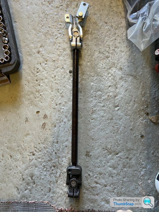
But according to this found on the forum:
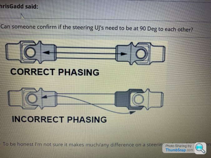
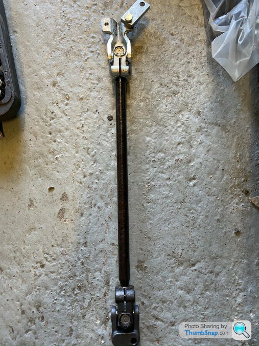
they should be set like this:
Apart from some play in the original UJs there was nothing amiss with the steering beforehand - does it matter?
p.s. the rack has been taken apart and re-conditioned so everything is being reset from the steering wheel in TDC position..
Thanks,
Steve
When I took the steering column out I marked the intermediate shaft to be able to put the new UJs on in the say place. They were in this position:
But according to this found on the forum:
they should be set like this:
Apart from some play in the original UJs there was nothing amiss with the steering beforehand - does it matter?
p.s. the rack has been taken apart and re-conditioned so everything is being reset from the steering wheel in TDC position..
Thanks,
Steve
The drawing is correct, but phazing Uj's is really more relevant with something like a propshaft whizzing round at thousands of rpm.
The speed a steering shaft turns at and the fact it turns less than a full turn, with the exception of parking, I can't in reality see it making a noticeable difference?
Nice little video
Ninja'd. But by Phillpot, so it's all right!
It's a double Cardan joint shaft. See here.
A single joint, operated at any significant angle, gives a 'jerky' output (I found this out when I was twelve, playing with Meccano). A second joint, correctly phased, 'un-jerks' its jerky input. Always provided the input and output shafts (of the whole assembly) are parallel to each other, and in the same plane (which they're not).
If incorrectly phased, the second joint will double the jerkiness!
Probably unimportant in our steering. Much more important in a gearbox-axle drive shaft, which can be rotating at 6000rpm or more.
It should be phased at 90 degrees as it was fitted.
Its different on a steering shaft than a prop, a prop shaft's two end's don't have to be able turn at different speeds its to do with the diameter of the column and the diameter of the pinion shaft. If they are the same then you wouldn't need to phase them at 90 degrees
It might feel sort of ok with the wheels in the air, but load it up and i think you might feel the difference.
GreenV8S said:
Bristol ave fag said:
Its different on a steering shaft than a prop, a prop shaft's two end's don't have to be able turn at different speeds its to do with the diameter of the column and the diameter of the pinion shaft.
No part of that makes any sense whatsoever.
Well it's all back together now - first attempt was 1-1/2 turns left and 1-5/8 right from a guessed centre position
With a bit of adjustment on the splines I have 1-9/16 (approx) turns each way to a full lock and a level steering wheel in the middle.
Now it's just top and bottom ball joints / hubs / dampers and track rod ends to refit and a trip to the alignment shop before we're back on the road.
Well, that's the plan.....
Thanks for everyone's help.
Steve

phillpot said:
GreenV8S said:
Bristol ave fag said:
Its different on a steering shaft than a prop, a prop shaft's two end's don't have to be able turn at different speeds its to do with the diameter of the column and the diameter of the pinion shaft.
No part of that makes any sense whatsoever.I would argue that you would want to have the UJ's in phase, as the steering shafts turn through significant angles. As you can see from this image, the output speed of a single UJ varies 'considerably' at 30°. This is why you should have another in phase to cancel the effects. This is unless you calculate the position carefully to achieve a variable steering ratio for a more sporty, positive feel.
https://ars.els-cdn.com/content/image/3-s2.0-B9780...
https://ars.els-cdn.com/content/image/3-s2.0-B9780...
Edited by WhatamIgettingmyselfinto on Monday 1st June 11:33
WhatamIgettingmyselfinto said:
I would argue that you would want to have the UJ's in phase, as the steering shafts turn through significant angles. As you can see from this image, the output speed of a single UJ varies massively at 30°. This is why you should have another in phase to cancel the effects. This is unless you calculate the position carefully to achieve a variable steering ratio for a more sporty, positive feel.
https://ars.els-cdn.com/content/image/3-s2.0-B9780...
They are all fitted the same way as the op's. Phased 90 degrees, The difference in the drive diameter (column) and the output diameter (pinion) sets up a gear ratio in the assembly and the top and bottom uj's are 2 physically different sizes.If the shafts were the same size then no gearing is introduced then you would be able to use 2 uj's that are physically the same and phase them differently.https://ars.els-cdn.com/content/image/3-s2.0-B9780...
In a nushell. Tvr use two different uj's on the same shaft and they are phased accordingly.
If you fit them wrong on these cars the steering will feel awful.
Edited by O mage on Monday 1st June 10:37
O mage said:
The difference in the drive diameter (column) and the output diameter (pinion) sets up a gear ratio in the assembly and the top and bottom uj's are 2 physically different sizes.If the shafts were the same size then no gearing is introduced then you would be able to use 2 uj's that are physically the same and phase them differently.
No, that isn't how it works. The shaft diameter is irrelevant to the effects being described here. It is purely a consequence of the geometry of a Hooke's joint.GreenV8S said:
No, that isn't how it works. The shaft diameter is irrelevant to the effects being described here. It is purely a consequence of the geometry of a Hooke's joint.
Thank god someone agrees haha.The other factors at play on a TVR (and most other cars with this setup) are the angles between the steering column and steering pinion planes. Either way both my S1 and S2 have the joints out of phase and I've always wondered if this is 'correct'. My dads Stag has an identical setup with the joints in phase. I think I'll give it a go when I replace my column bush and report back.
GreenV8S said:
No, that isn't how it works. The shaft diameter is irrelevant to the effects being described here. It is purely a consequence of the geometry of a Hooke's joint.
I dont want to argue, i have explained how it is. In any set up if the diameter of the driver is the same as the driven then its 1 to 1. if the driver and driven are of different sizes then that sets up a different ratio.!.
Would you like tell us why they are all fitted this way then. ?
O mage said:
I dont want to argue, i have explained how it is. In any set up if the diameter of the driver is the same as the driven then its 1 to 1. if the driver and driven are of different sizes then that sets up a different ratio.!
.
Would you like tell us why they are all fitted this way then. ?
The shaft could be a metre in diameter or as thin as a knitting needle, but its still rigidly connected to the same universal joint. It's the angle of the joint which will cause a sinusoidal change in shaft speed through each rotation..
Would you like tell us why they are all fitted this way then. ?
If the shafts are perfectly aligned then they would all spin at a constant speed no matter the orientation.
When you want an output speed to be constant whilst allowing for changes in intermediate shaft angle, such as in a drive shaft, then the joints are arranged in phase to cancel the effects of joint angles There are some exceptions, such as in Land Rover prop shafts, where the joints are assembled at some angle to allow for greater travel iirc?
Anyway, in all cases it's the geometry of the joints which dictates the shaft speeds.
Edited by WhatamIgettingmyselfinto on Monday 1st June 11:26
Edited by WhatamIgettingmyselfinto on Monday 1st June 11:27
WhatamIgettingmyselfinto said:
O mage said:
I dont want to argue, i have explained how it is. In any set up if the diameter of the driver is the same as the driven then its 1 to 1. if the driver and driven are of different sizes then that sets up a different ratio.!
.
Would you like tell us why they are all fitted this way then. ?
The shaft could be a metre in diameter or as thin as a knitting needle, but its still rigidly connected to the same universal joint. It's the angle of the joint which will cause a sinusoidal change in shaft speed through each rotation..
Would you like tell us why they are all fitted this way then. ?
If the shafts are perfectly aligned then they would all spin at a constant speed no matter the orientation.
When you want an output speed to be constant whilst allowing for changes in intermediate shaft angle, such as in a drive shaft, then the joints are arranged in phase to cancel the effects of joint angles There are some exceptions, such as in Land Rover prop shafts, where the joints are assembled at some angle to allow for greater travel iirc?
Anyway, in all cases it's the geometry of the joints which dictates the shaft speeds.
Edited by WhatamIgettingmyselfinto on Monday 1st June 11:26
Edited by WhatamIgettingmyselfinto on Monday 1st June 11:27
Gassing Station | S Series | Top of Page | What's New | My Stuff