Electric boot release and remote controler
Discussion


Hi guys,
The good season is over, It's now time to finish all pending works.... suspended by the season to enjoy this great car .... 8k miles this season
I installed a Chinese central locking system with a remote controller last winter. It's not really useful to open a 2-seater-car doors, but it's really helpful to open the boot. The door locking is working well... but the boot don't It took me some time to understand why the actuator was not working when sending a ground to the switch exit.... and not better with a +12V. Now I know :
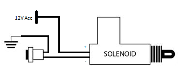
If I send a ground, it works, but only with the ignition ON.... No interest.
If I modify the power supply by a permanent 12V, the switch will release the boot without any key.... That's not what I want.
The solution is to use a make/break relay. The NC contact will be use in +12V ACC and the NO will be use with the +12V permanent.
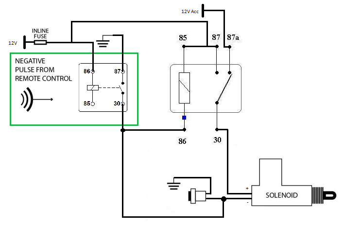
But to do that, I have to find the boot harness in the car with the 2 wires. It's easy to find the harness in the boot. It's easy to find the wire on the switch. But it's not so easy to find the boot harness, with the +12V Acc. Could anybody help me to find it in the car ? (wire colour), harness path from front to rear.
Thanks.
The good season is over, It's now time to finish all pending works.... suspended by the season to enjoy this great car .... 8k miles this season
I installed a Chinese central locking system with a remote controller last winter. It's not really useful to open a 2-seater-car doors, but it's really helpful to open the boot. The door locking is working well... but the boot don't
It took me some time to understand why the actuator was not working when sending a ground to the switch exit.... and not better with a +12V. Now I know :If I send a ground, it works, but only with the ignition ON.... No interest.
If I modify the power supply by a permanent 12V, the switch will release the boot without any key.... That's not what I want.
The solution is to use a make/break relay. The NC contact will be use in +12V ACC and the NO will be use with the +12V permanent.
But to do that, I have to find the boot harness in the car with the 2 wires. It's easy to find the harness in the boot. It's easy to find the wire on the switch. But it's not so easy to find the boot harness, with the +12V Acc. Could anybody help me to find it in the car ? (wire colour), harness path from front to rear.
Thanks.
Hi..
I too, as part of my S3 restoration project am including fitting of a new central locking controller. At the moment, I have just allocated the controller's physical location, with all wires just hanging ! However I totally get your diagram and needing an 'aux' power supply feed.
My existing boot release power supply is Ign fed, not 'aux', and thats on the existing boot release relay on the main fuse board (not as per your first diagram).
On doing other electrical work (adding new USB & cigar type sockets) I found that the only 'aux' on my car, is the radio supply. That wire runs directly from the ignition key switch to the radio plug (except for the connector close to the ignition key switch).
So maybe that's something you can use.
Oh, don't forget, there isn't a fuse in that 'aux' supply, although I have added an inline fuse instead of that connector.
T.
Edited by Blue 30 on Friday 25th October 16:15
Edited by Blue 30 on Friday 25th October 16:17
Edited by Blue 30 on Friday 25th October 16:18
Fefeu52 said:
But it's not so easy to find the boot harness, with the +12V Acc. Could anybody help me to find it in the car ? (wire colour), harness path from front to rear.
I'm not sure I understand your question correctly, but it reads like you're trying to find an Acc feed in the rear loom. There isn't one. You'd need to put the boot release controller up front under the dashboard connected to the Acc and permanent live supplies, and just use the existing wire to connect your relay output to the boot release solenoid (or add a wire if you were converting from a mechanical release).Sorry for my poor English. You're right, I used "Acc 12v" instead of "ignition 12v". That's right I have to turn the key to the second position (ignition) to be able to open the boot. The first position (Acc) is not enough.
In fact I'm only looking for the genuine boot release harness. Where does it come inside the car ?
In fact I'm only looking for the genuine boot release harness. Where does it come inside the car ?
Fefeu52 said:
Sorry for my poor English. You're right, I used "Acc 12v" instead of "ignition 12v". That's right I have to turn the key to the second position (ignition) to be able to open the boot. The first position (Acc) is not enough.
In fact I'm only looking for the genuine boot release harness. Where does it come inside the car ?
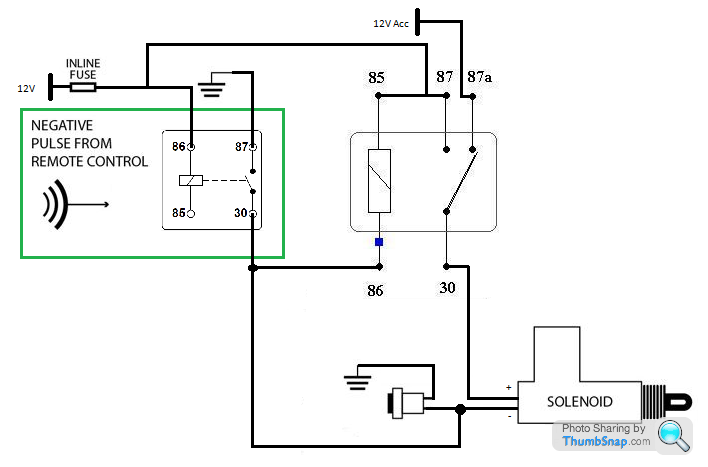
Connecting Relay terminal 87a to ignition will not workIn fact I'm only looking for the genuine boot release harness. Where does it come inside the car ?
The circuit diagram above will not work
Connect it all up as above and listen to the Relay buzz all day every day until the battery goes flat


As you are trusting the controller's technology to look after the door locking (with the door key being the fail safe device), why not delete the boot release manual push button and let the remote fob open the boot ?
By adding the mechanical cable release you will have a fail safe device.
Plus if the controller did ever fail, you could simply remove the relay and 'flash' a jump lead between input and output.
T.
By adding the mechanical cable release you will have a fail safe device.
Plus if the controller did ever fail, you could simply remove the relay and 'flash' a jump lead between input and output.
T.
Penelope Stopit said:
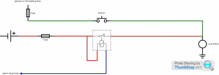
The above diagram gives you what you wish to have
Thanks for the diagram. You'r right reversing the system by switching power cable instead of the ground is the easiest solution. Penelope Stopit said:
Have you considered using the drivers door interior light switch to operate a relay that could be used to power the push button?
To be honest, no. Because my first idea was to keep the system as it is, and add my system to operate in parallel. Blue 30 said:
As you are trusting the controller's technology to look after the door locking (with the door key being the fail safe device), why not delete the boot release manual push button and let the remote fob open the boot ?
By adding the mechanical cable release you will have a fail safe device.
Plus if the controller did ever fail, you could simply remove the relay and 'flash' a jump lead between input and output.
T.
That's right. There is no interest to keep the steering column switch. The cable is enough for security.By adding the mechanical cable release you will have a fail safe device.
Plus if the controller did ever fail, you could simply remove the relay and 'flash' a jump lead between input and output.
T.
Blue 30 said:
The boot solenoid wiring comes from the boot release relay located on the main fuse/relay board under the dashboard (as seen on the S290 wiring diagram).
Sorry but I don't find it on the S290 wiring diagram
Gassing Station | S Series | Top of Page | What's New | My Stuff